

Page 1

LRU
User Manual
March 2002
Page 2

To contact SERCEL
Nantes, France
Commercial; Customer Support;
Manufacturing & Repair.
B.P. 439, 16 rue de Bel Air
44474 Carquefou Cedex
Tel: +33 2 40 30 11 81, Fax: +33 2 40 30 19 48
Hot-Line: Land: +33 2 40 30 58 88
Marine: +33 2 40 30 59 59
E-mail: sales@sercel.fr
customer.support@sercel.fr
www.sercel.com
St Gaudens, France
Vibrator Customer Support;
Vibrator Manufacturing & Repair;
Streamer Manufacturing & Repair.
Tel: +33 5 61 89 90 00, Fax: +33 5 61 89 90 45
Hot Line: +33 5 61 89 90 91
Alfreton, U. K.
Streamer Manufacturing & Repair;
Customer Support.
Tel: +44 1 773 605 078, Fax: +44 1 773 541 778
Houston, USA
Commercial; Customer Support;
Manufacturing & Repair;
Streamer Manufacturing & Repair.
Tel: +1 281 492 66 88, Fax: +1 281 492 69 10
Hot-Line: +1 281 492 66 88
E-mail: sales.hou@sercelus.com
training.hou@sercelus.com
customer.support@sercelus.com
Ponca City, USA
Vibrator Customer Support;
Vibrator Manufacturing & Repair.
Tel: +1 580 763 00 00, Fax: +1 580 763 00 22
Moscow, Russia
Commercial; Customer Support.
Tel: +7 095 254 06 59, Fax: +7 095 254 66 80
Beijing, P. R. of China
Commercial; Customer Support.
Tel: +86 106 43 76 661, Fax: +86 106 43 76 3 07
Tanggu, P. R. of China
Manufacturing & Repair.
Tel:+86 222 58 23 224 , Fax:+86 222 58 23 242
Xian, P. R. of China
Manufacturing & Repair.
Tel: +86 297 85 25 05, Fax: +86 297 85 55 04
Singapore
Streamer Manufacturing & Repair;
Customer Support.
Tel:+65 545 0411, Fax:+65 545 1418
Dehradun, India
Customer Support.
Tel: +91 135 773 387, Fax: +91 135 773 132
E-mail: sercel@nde.vsnl.net.in
In no event shall SERCEL be liable for incidental or consequential damages or related expenses
resulting from the use of this product, or arising out of or related to this manual or the information contained in it, even if SERCEL has been advised, or knew or should have known of the
possibility of such damages.
The information included in this documentation is believed to be accurate and reliable.
However, SERCEL reserves the right to make changes to its products or specifications at any
time, without notice, in order to improve design or performance and to supply the best possible
product. This documentation does not form in any way a contractual agreement of sales
promise on the part of SERCEL.
Software mentioned in this documentation is sold under a precise licence agreement and as
such the documentation may cover technical areas for which the user may not have a final
licence.
No part of this documentation, or any of the information included herein may be modified or
copied in any form or by any means without the prior written consent of SERCEL.
Acknowledgments: All brand or product names are trademarks or registered trademarks of
their respective companies or organizations.
Page 3

LRU User Manual
General
The LRU (Line Remote Unit) relay is a long range po int-t o-p oint ra di o
relay cell that can be inserted anywhere in a spread as an element of the
408UL network to re lay the data transmission o n a Line or a Transverse.
It connects to any type of 408UL field electronics (LAUX, LAUL, FDU
Link, etc.). Built in the LRU is a full per formance LAUX.
In the LRU transmission pro tocol (Half-du plex), time i s shared betwee n
transmission of Master-to-Slave messages and transmission of Slaveto-Master messages.
Master-to-Slave messages are called Network Control Sequences
(NCS), used for synchronization, zero-time transm ission and contro l.
Slave-to-Master messages are called Data Transfer Sequences (DTS),
used for data retrieval, seismonitor and collec ting test results.
1-1
Page 4
Typical setups
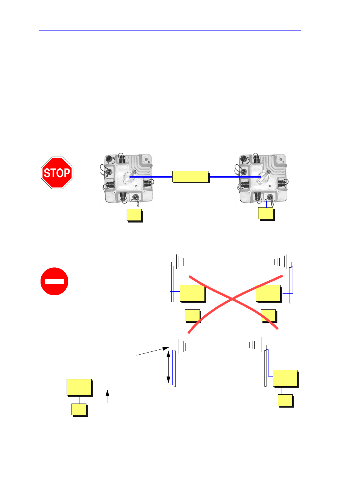
CAUTION
If you wish to test a radio relay cell through a wireline link between the
coaxial connectors of two LRUs, use a 60 dB (minimum), 20 W
attenuator.
Attenuator
20 W
60 dB min.
Typical setups
12 V
For optimal performance of
the radio link, do not
place any electric
device (including LRU,
FDPA408, etc.) on the
same side as the radia ting
elements!
Do not raise any antenna
near electric power
distribution lines!
The antenna should be at
the top the mast.
LRU
(test setup)
8 m
LRU
12 V
NO
YES
12 V
LRU
12 V
LRU
1-2
12 V
12 V
Use the whole cable length
to keep clear fro m the anten na .
March 2002
Page 5

LRU User Manual Typical setups
CAUTION
Antenna height is limite d to 6.1 metre near airports .
Below are typical examples of setups along with the associated
specifications in terms of covered range and transmission capacity.
Basic radio relay cell
.
LAUX and
radio functions
See
below
Line or
Transverse
to Central
Unit
1
Typical performance (Ground-Wave propagation above flat
LRU
12 V
Battery
Coax downlead
1
7-element
Yagi antenna
LRU
12 V
terrain):
- Range: 24 km, 60 Ch @ 2 ms, Real time.
- Range: 10 km, 240 Ch @ 2 ms, Real time.
See
CAUTION
on
page 1-2
.
For the Left/Right and Low/High ports of the LRU, connect as usual
(Left to Right; Low to High).
1-3
Page 6

Radio relay in series connection
To extend the relay range, you can use two relay cells in series
connection a s shown below. You can choose between two types of
series setups, one with fewer antenna masts to raise, the other
optimizing th e da ta rate.
• Two-mast series setup (high data rate)
Requirements:
- At least 300 m between antenna s,
- At least 13 MHz frequency separation.
Typical setups
Line or
Transverse
to Central
Unit
Battery
1
Typical performance of each relay cell (Ground-Wave propagation
LRU
12 V
For optimal
performance,
use vertical polarization in one cell
and horizontal in
the other.
See
below
1
LRU
12 V
LRU
12 V
Line or
Transverse ports
See
below
1
LRU
12 V
above flat terrain):
- Range: 24 km, 60 Ch @ 2 ms, Real time.
- Range: 10 km, 240 Ch @ 2 ms, Real time.
Setups with more than two relay cells in serie s connection have not bee n
tested yet.
See CAUTION on
1-4
page 1-2
.
March 2002
Page 7

LRU User Manual Typical setups
• Single-mast series setup
Line or
Transverse
to Central
Unit
Battery
LRU
12 V
See
below
LRU
12 V
1
(Line or
Transverse
cable)
LRU
12 V
See
below
1
LRU
12 V
1
Typical performance of each relay cell (in Ground-Wave
propagation conditions above flat terrain):
- Range: 24 km, 30 Ch @ 2 ms, Real time.
- Range: 10 km, 120 Ch @ 2 ms, Real time.
For the single-m ast serie s s etu p, a spe ci al sof twar e con fig urati on ne eds
to be programm ed in the LR Us, us in g an FD PA408 po cket term in al or
the 408UL HCI workstati on: in each intermediate pair, not to have one
of the LRUs transmitting while the other is receiving, you must have
them working on two distinct “
Subframes
”. That’s why the date rate is
divided by two in the above exampl e.
See LRU Operational Description.
1-5
Page 8

Typical setups
Where more than two relay cells are used in “single-mast series
connection”, you can avoid reducing the data rate any further if you still
work with only tw o Subframes, provide d adjacent relay loc ations do not
use the same Subframe.
In the example below, relay cell (A) can use the sa me Subframe as relay
cell (C) if they are distan t enough and if the y use two separate frequency
channels.
LRU 1
Relay
Cell
(A)
(B)
(C)
(A)
LRU
No.
LRU 2
LRU 3
Transmit on
Subframe 1
(B)
LRU 4
LRU 5
1 ✔
2 ✔
3 ✔
4 ✔
5 ✔
6 ✔
(C)
Transmit on
Subframe 2
LRU 6
1-6
March 2002
Page 9

LRU User Manual Typical setups
Radio relay with REM
Line or
Transverse
to Central
Unit
LRU
12 V
Battery
See
below
Requirements:
- At least 300 m between antennas,
- At least 13 MHz frequency
separation.
1
SU6R
LRU
12 V
REM
SU6R
Insert a
bandpass
cavity filter for
each REM
(case of multi-REM
setup) and one
more if Audio is
used with SU6-R
SU6R
(Transverse cable)
1
Typical performance of each relay cell (in Ground-Wave above flat
12 V
terrain):
- Range: 24 km, 60 Ch @ 2 ms, Real time.
- Range: 10 km, 240 Ch @ 2 ms, Real time.
The antenna of the REM and the antenna of the LRU attached to that
REM can be mounted on the same mast, but in that case a minimum
vertical separation of 30 metres (100 feet) should be provided. The rule
is to have at least 80 dB attenuation between the two antennas to allow
each system to work at i ts full sensitivity. The cavity f ilters for the
REMs are still require d.
A REM upgrade may be required.
See CAUTION on
page 1-2
.
1-7
Page 10

SU6R
Requirements:
- At least 300 m between antennas,
- At least 13 MHz frequency
separation.
Typical setups
SU6R
SU6R
SU6R
REM
12 V
LRU
12 V
up to 24 km
LRU
12 V
REM
12 V
1-8
March 2002
Page 11

LRU User Manual Antennas
Antennas
The LRU is used as a point-to-point radio relay. For a stationary relay,
directional antennas are used, allowing maximum performance and
protection from int erferen ce. Whe re one of th e two LR Us involv ed in a
radio relay is subjec t to rovin g (Marine, S halow-wa ter operati on, etc.)
omni-directional antennas are more suitable.
Directional antenna
Below are the specifications of a wide-band, 7-element Yagi antenna
available from SERCEL.
This directional antenna can be used either horizontally or vertically.
A 50-ohm impedance coax cable should be used to connect the antenna
to the LRU. To increase the system performance, a low-attenuation,
double-shie l d coa x cable is recommen de d.
Prior to using the antenna, especially after assembly, a VSWR check
should be done, including the coax cable. The maximum VSWR within
the bandwidth of interest should be less than 1.5:1 to work in good
conditions.
• Specifications
• Type: Wideband 7-Element Yagi
(Sercel P/N: 07-820070-001).
• Frequency: 215 to 240 MHz.
• Power Gain: 10.5 dBi, Center frequency.
• VSWR: 1.6:1 Max.
1.3:1 Center f r equency.
• Front-to-back Ratio: 20.45 dB, Center frequency
• 3-dB beamwidth: E = 48 degrees.
H = 57 degrees
1-9
Page 12

• Feed Impedance: 50 ohm.
• Connector type Type UHF.
• Antenna Boom length: 1.9 m (75").
• Longest Element: 68 cm (26.772").
• Shortest Element: 48 cm (18. 898'').
• Weight: 900 g (2 lb).
• Maximum mast OD: 5 cm (2").
Antennas
1-10
March 2002
Page 13

LRU Specifications
GENERAL
Radio Functions Communication with another LRU
Cable Functions full LAUX capabilities
Tests capabilities Power supply
Antenna spectrum monitoring capability
Radio setup Pocket terminal connection
Memory 4Mb local buffer for non-real time
Interval between
LRU's or LRU and LAUX
on transverse Up to 300 m with ST cable
for data transmission with error
recovery and temporary storage
Radio data transmission
Cable data transmission
Field tests
Instrument tests
capability
transmission mode
Up to 250 m with WPSR
Up to 400 m with WPSRLR
RADIO PERFORMANCES
Radio link between LRU’s
(Typical propagation condition, bit error rate better than 10
8 m (26 feet) antenna mast, Yagi type antenna)
- 16 km (10 miles) up to 240 Channels (*) @2ms sample
rate real time retrieval.
- 24 km (15 miles) up to 60 Channels (*) @2ms sample
rate real time retrieval.
-6
PHYSICAL
Material Aluminium
Dimension and Weights
Size
Weigths 12.6 kg (27.8 lbs)
Power
Operating Power Voltage
Power consumption
Operating Temperatures
Storage Temperatures
Water Depth 1.5 m
,
380x380x225 mm (14.9x14.9x8.8 in)
10.5 to 15 VDC, 2 battery
connectors, to allow
uninterrupted operation during
battery replacement
Master : 23 W
Slave : 80 W when retrieving
Sleep : 1,2 W
-40°C to 70°C
-40°C to 70°C
RF Characteristics :
RF Frequencies USA use : limited to 216 MHz to
RF Output Power RF power management ; 6W nominal
RF Output
Impedance 50 Ω
FCC Emission
Designators 250KD1D and 800KD1D
218 MHz and 219 MHz to 220 MHz
Canadian use : limited to 217 MHz to
218 MHz and 219 MHz to 220 MHz
Other countries : in respect with local
regulation
Overall capability : 215 MHz to 250 MHz
CABLE PERFORMANCES
(Typical @ 2 ms sample rate and 25°C)
Maximum number of FDU's per LRU :
- 120 with up to 30 m interval
- 96 with up to 55 m interval
- 80 with up to 75 m interval
Maximum number of FDU's between LRU's or between LRU
and LAU :
- 60 with up to 30 m interval
- 48 with up to 55 m interval
- 40 with up to 75 m interval
(*) the number of channels increases proportionally with the ratio :
(shot cycle time) / (acquisition time).
 Loading...