


Exhibit C-Operators Manual
Installation Manual Description of the radio telemetry equipment
Spectru
Description of the radio telemetry equipment
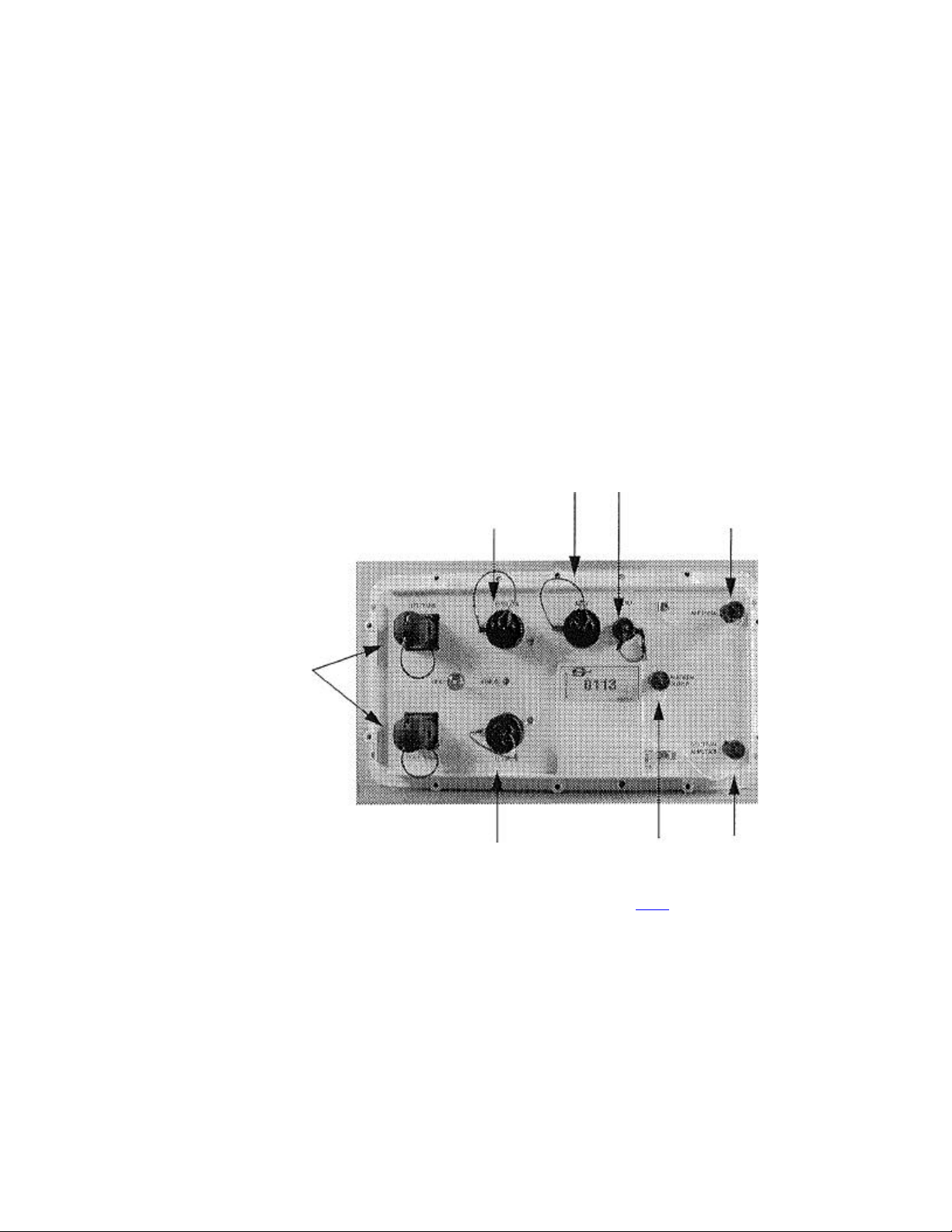
Remote Eagle Module (REM)
The REM connects to the Left or Right Transverse connector of an LAUX, or a
408UL control module or another REM. It interfaces a radio cell with a wireline
telemetry section or with the CM408 or 408XL. It is used to control the digitizer
units (SU6-R) in a radio cell and retrieve the seismic data from it.
12 VDC XDEV Audio RF Power
power supply output
input to antenna
Transverse connectors
12 VDC Multi-REM
power supply output
input
Main specifications
of the REM:
· Operates
from 12
VDC (a
standard 12
V battery).
· Data
reception rate: 400 kbit/s.
· 16 000 sample buffer per channel; acquisition capacity: 32 s@2
1T2S.
m
analyzer
· Transmit/receive frequencies: 216 to 230 MHz in 50-kHz steps;
0311400 8-3

Description of the radio telemetry equipment
l0 W RF output~ power (rain);
One REM in each RF cell (1 retrieve frequency);
Up to six REMs can be used on one antenna;
Maximum number of REMs in a network: 16;
Typical range: 16 to 24 km (10 to 15 miles).
The REM has a built-in signal strength meter used to monitor the RF Spectrum on
the HCI workstation, and an output for connection to an external spectrum analyzer
with a finer resolution. The signal available on the Spectrum Analyzer output is
picked up at the antenna with a 20 dB gain.
Preamplifier
If a preamplifier is used between the antenna and the Antenna connector on a REM,
then the REM Layout Setup on the HCI workstation must let the REM supply a 12
V DC voltage to the preamplifier over the antenna downlead in receive mode.
If any filter is used that does not relay DC voltage, then a DC Block must be used to
supply power to the preamplifier.
8-4 March 2001

Installation Manual Description of the radio telemetry equipment
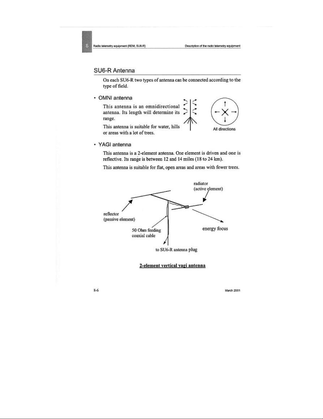
SU6-R
The SU6-R is a six-channel field digitizer unit used in radio telemetry cells. It uses
a radio link to communicate with a REM. All the SU6-Rs are completely
independent and can coyer any type of field.
In the event of obstruction along an RF radio path to the REM, a simple wire
telemetry link can be used in place of the RF link.
The SU6-R uses a small, light-weight, ragged aluminum package for reliability and
reduced transportation effort.
Its main features are the following:
· A rechargeable nickel-cadmium 0NJ-Cad) battery pack.
· Analog-filter-free and ideal seismic response. Taking advantage of the large
dynamic range and the very low distortion of the SU6-Rs 24-bit-stream A/D
converter, the seismic channels are free from any analog filters. With this design,
idem seismic response with linear phase shift is achieved, as undesirable phase
shifts and temperature drifts otherwise associated with analog components are
eliminated. Also, no filter setting is required at the field level, which precludes any
unrecoverable error that might otherwise arise from incorrect filter settings.
· A low distortion built-in test generator is integrated into every SU6-R, in order to
performance a remote check of the complete acquisition performance, at full
specification, from the central control unit without any external oscillator.
· Internal memory that allows simultaneous collection and retrieval of seismic data.
Shot stacking may also be performed by the SU6-R.
· Each field unit is assigned to a specific frequency upon deployment by the
control unit.
NOTE: The SU6-R is fully compatible with SERCEL-OPSEIS SARs.
0311400 8-5
Installation Manual Description of the radio telemetry equipment
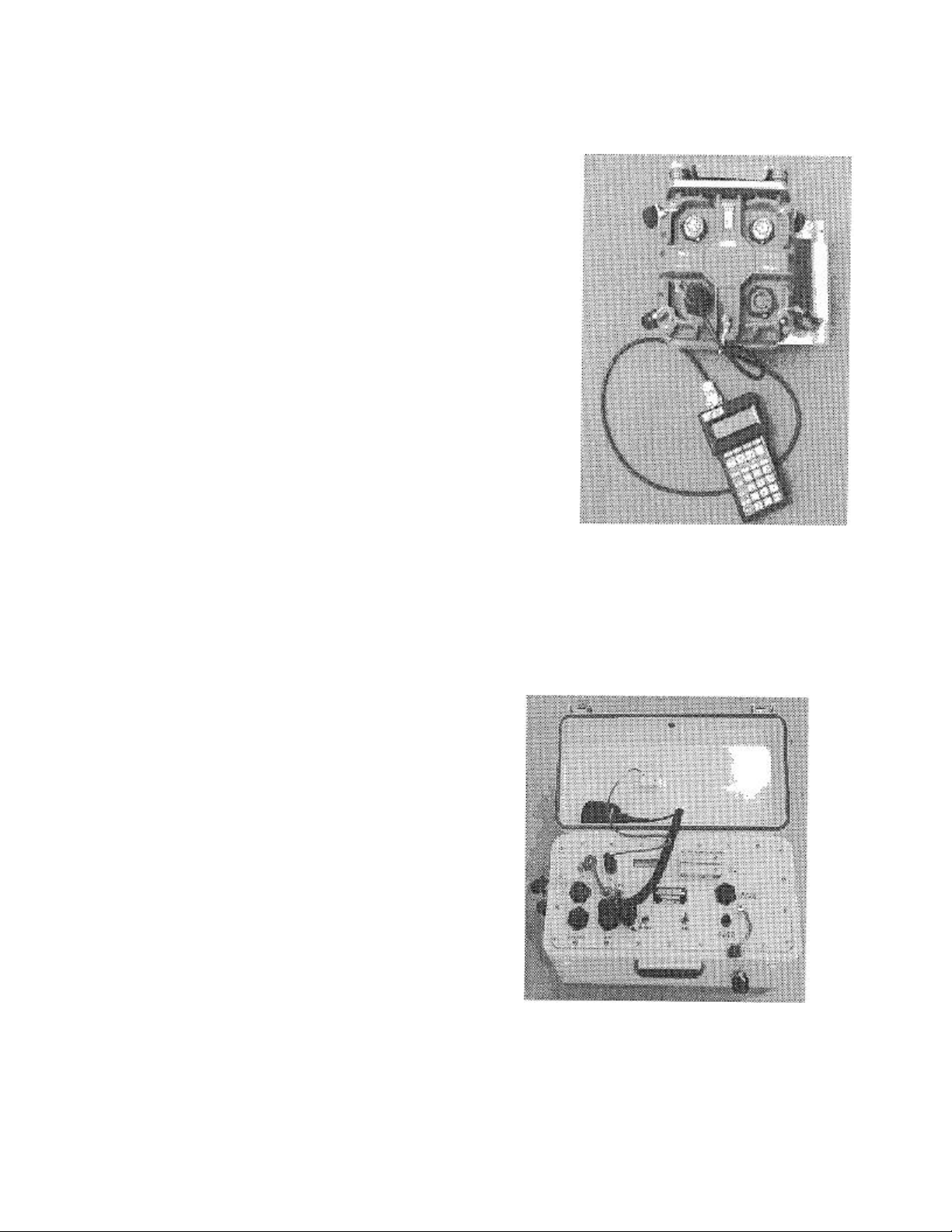
FDPA (Field Deployment aid)
The FDPA is a small hand-held terminal
that allows you to program, monitor and
test certain aspects of the setup for an
SU6-R. Typically the checks are performed
at the time of physical SU6-R deployment
in order to speed up deployment.
The FDPA activates the SU6-Rs power-up
self-test, can evaluate cable leakage and
continuity tests, and assign the SU6-R
address and SU6-R wire-line function.
The FDPA receives its power from the
connected SU6-R. The test results are
displayed on a 4-line, 20-column LCD screen.
Multi-frequency RF Blaster
The RF Blaster Unit, is a
portable, internally batterypowered unit the shooter uses
'to initiate shot point
operations.
The RF Blaster sends and receives
commands, and transmits data to the
central control unit via its own RF
transceiver.
0311400 8-7

Radio telemetry equipment (REM, SU6-R) Description of the radio telemetry equipment
Battery charger
It's a portable 8-hour charger designed to simultaneously charge 1 to 36 SU6-Rs.
There are 6 charging cables. Each cable can charge up to six SU6-R units.
LED circuits provide a visual indication of the charging process. Since each of the
chargers is fully automatic, a battery can be connected to or disconnected from the
charger independently of the others. A battery does not have to be fully discharged
before it can be connected to the charger.
Power Unit Capacity Tester.
The Power Unit Capacity Tester (PUCT) can perform capacity
testing on SU6-R Power Units to verify their performance before
use on the field. It's basically a capacity tester with control circuitry
to improve operation. It lets a user view the test and status results.
The PUCT can also help rejuvenate battery packs suffering from
"voltage depression".
8-8 March 2001


Radio telemetry equipment (REM, SU6-R) Connecting REMs
Connecting REMs
Minimum distance requirements
In order not to overload the receiving stage in REMs and SU6-Rs, the following minimum
distances are required:
between REM and SU6-R: 100 m (300 ft);
between REMs: 300 m (1000 ft);
between SU6-Rs: 100 m (300 ft).
These are approximate values, depending on the type and direction of the antenna and on
various RF transmission parameters.
8-10 March 2001


Installation Manual Cab-mount aerial installation
Compressor setting
For in-depth information, please refer to the manufacturer's document.
Before using the air compressor on the field, the primary pressure switch sensing the receiver
should be set according to the motor maximum compression capacity in order not to damage
the motor.
For a 50 PSI maximum compression capacity given as an example, the motor should start
when the receiver pressure falls around 25 PSI and stop at 50. To set the pressure switch
correctly, use the following procedure:
· Remove the pressure switch cover to access the two adjusting screws.
WARNING
The four terminal screws are at line voltage and present a shock hazard.
Turn the center adjusting screw counter-clockwise to decrease cut-in pressure (ON) and cutout pressure (OFF).
To change the cut-out pressure without affecting the cut-in setting, turn the off-center screw
clockwise to increase the setting or counterclockwise to decrease the setting.
To check the settings, release air from the system until the compressor starts and note the
pressure gauge reading when it comes on, then dose the air valve and note the pressure at
which the compressor shuts off.
0311400 March 2001

Radio telemetry equipment (REM, SU6-R) Cab-mount aerial installation
Rotator Setting
The information given below concerns the AR-40 Antenna Rotator manufactured by Hy-Gain.
For in-depth description, the user should refer to the manufacturer documents.
Pre-Installation Check and Calibration.
Before mounting the rotator unit on the considered mast or tower, check the operation with the
control unit and cable. Strip all conductors at both ends of the cable and attach to the
terminals. Connect terminal 1 to terminal 1, etc. On the control box, simply insert the bare
wire between the nut and the terminal and tighten the screw. Do not wrap the wire around the
screw!
Plug the control unit line cord into a convenient wall outlet. Turn the direction control knob to
'N'. Momentarily press down on the start button. The rotator will start to turn and the indicator
light will come on. When the rotator reaches 'N', it will automatically stop and light-will go
off.
Turn the knob COUNTERCLOCKW/SE to 'S' and press the start button. If the rotator unit
stops before the South position and the indicator light turns off, adjust the 'CCW end of
rotation' shaft counterclockwise as far as it will go. The adjustments for end of rotation are
located on the bottom side of the control box. Tm~ the unit to 'W', stop, then again to 'S', using
the method as described previously. If the control light remains on this time, slowly turn the
'CCW' shaft clockwise until the light goes off.
Turn the knob CLOCKWISE to 'S' and press the start button. The rotator unit should turn
clockwise toward the 'SOUTH' position. If the rotator stops before reaching the 'SOUTH'
position and the indicator light turns off, adjust the 'CW end of rotation' shaft clockwise as far
as it will go. Turn the unit to 'E', stop, then again 'back to 'S'. If the light remains on, slowly
turn the 'CW' shaft counterclockwise until the light turn off.
8-16 March 2001

Installation Manual Cab-mount aerial installation
Leave both rotators in the 'NORTH' position for the mast and antennae array indexing and put a pen mark on
upper and lower parts of each rotator so that the 'NORTH' position is dearly visible.
Typical setting of the cab-mount antenna
After installing the antenna (see Cab-mount aerial installation on page 8-14), a variety of
adjustments can be considered with a view to coveting your specific spread performance. But
before attempting any adjustment, the recording unit has to be located to optimise the system's
RF performance.
Choosing a good site involves prior planning. An advance party and survey crew typically
provides site information, including a suggested spot to place the Recording Unit.
It is also helpful to consult a topographical map.
A recording unit is situated for best operation when located:
· Out of hazardous areas.
STOP CAUTION
Do not raise any system antenna near electrical power distribution lines.
· At maximum possible elevation for optimum RF performance.
· At the most suitable place to minimize REM re-location during the operation.
· Away from tall, dense foliage and other objects that could possibly attenuate RF signals.
· Away from outside RF interference patterns.
· Within the system's RF range, which is typically 12 to 24 km% but will vary in relation to
the above listed conditions configurations with two stacked 7-element YAGI dual arrays.
OMNI 12 - 18 km (8 - 11 miles)
Yagi 18 - 24 km (11 - 15 miles)
0311400 8-17


Radio telemetry equipment (REM, SU6-R) S U6-R deployment
SU6-R deployment
Overview
Controlled by operational commands on the transmit frequency from the Remote Eagle
Module (REM), the microprocessor in the SU6-R can receive, convert, stack, store and
transmit (on the REM receive frequency) seismic data to be processed by the CM408 or
CMXL.
With up to six REMs in the master/slave configuration, the data can be retrieved
simultaneously from all. SU6Rs on up to six frequencies. In case of radio restrictions, a simple
wire telemetry link can be used in place of the RE link. To transmit data, two modes are
available:
RF mode;
Wire-Link mode.
For general requirements relating to radio transmission and power supply, see the following
paragraphs:
· Typical setting of the cab-mount antenna (page 8-17) · SU6-R signal Quality Control (page
8-31) o Conditions Affecting Reception (page 8-32)
· SU6-R Battery Management (page 8-34)
· FDPA - Field Deployment Aid (page 8~37)
The connectors on the SU6-R consist of:
- Two geophone connectors - GEO A and GEO B:
Used to input seismic signals into the SU6-R.
- WL/DPA (Wire Line / Field Deployment Aid) connector:
Used for Wire Line operation. This port connects to other Master or Slave units by a
Wire-Line cable.
Used for field checks and setup (FDPA).
8-22 March 2001
 Loading...