

Page 1
LRC
-
508
USER MANUAL
1
Page 2

Europe
Russia
To contact Sercel
Nantes, France
Sales; Customer Support;
Manufacturing & Repair.
B.P. 30439, 16 rue de Bel Air
44474 Carquefou Cedex
Tel: +33 2 40 30 11 81, Fax: +33 2 40 30 19 48
Hot-Line: Land: +33 2 40 30 58 88
Marine: +33 2 40 30 59 59
Navigation: +33 2 40 30 69 87
E-mail: sales.nantes@sercel.com
customersupport.land@sercel.com
customersupport.marine@sercel.com
customersupport.navigation@sercel.com
repair.france@sercel.com
streamer.repair@sercel.com
www.sercel.com
St Gaudens, France
Vibrator Customer Support;
Vibrator Manufacturing & Repair;
Streamer Manufacturing & Repair.
Tel: +33 5 61 89 90 00, Fax: +33 5 61 89 90 33
Hot Line: +33 5 61 89 90 91
E-mail: customersupport.vib@sercel.com
customersupport.vsp@sercel.com
Les Ulis, France
Sales; Customer Support
Tel: +33 1 69 93 83 60, Fax: +33 1 69 81 78 09
E-mail: vspsupport@sercel.com
Hot Line: +33 6 15 54 13 96
Brest, France
Sales; Customer Support
Tel: +33 2 98 05 29 05; Fax: +33 2 98 05 52 41
E-mail: sales.nantes@sercel.com
Toulon, France
Sales; Customer Support
Tel: +33 4 94 21 69 92; Fax: +33 4 94 21 73 44
E-mail: SalesMSBU@sercel.com
SupportMSBU@sercel.com
Toulouse, France
Sales; Customer Support
Tel: +33 5 61 34 80 74; Fax:+33 5 61 34 80 66
E-mail: support@metrolog.com
sales@metrolog.com, info@metrolog.com
Alfreton, U. K.
Streamer Manufacturing & Repair;
Customer Support.
Tel: +44 1 773 605 078, Fax: +44 1 773 541 778
E-mail: streamer.repair@sercel.com
Trondheim, Norway (Optoplan AS)
Tel: +47 73820500, Fax: +47 73820599
Dortmund, Germany
Manufacturing.
DE REGT Tel: +49 2 31 65 55 64 11.
Customer Support; Repair.
Moscow, Russia
Tel: +7 495 644 08 05, Fax: +7 495 644 08 04
E-mail: repair.cis@geo-mail.org
support.cis@geo-mail.org
Surgut, Russia
Tel: +7 3462 28 92 50
North America
Houston, Texas, USA
Sales; Customer Support;
Manufacturing & Repair;
Tel: +1 281 492 66 88, Fax: +1 281 579 75 05
Hot-Line: +1 281 492 66 88
E-mail:
sales.houston@sercel.com
HOU_Customer.Support@sercel.com
HOU_Training@sercel.com
HOU_Customer.Repair@sercel.com
Tulsa, Oklahoma, USA
Tel: +1 918 834 96 00, Fax: +1 918 838 88 46
E-mail:
support@sercel-grc.com
sales@sercel-grc.com
Calgary, Alberta, Canada
Sales; Customer Support; Manufacturing.
Tel: +1 403 275 3544, Fax: +1 403 295 1805
E-mail:
Cal_Customer.Support@sercel.com
Middle East
Dubai, U. A. E.
Sales, Customer Support, Repair.
Tel: +971 4 8832142, Fax: +971 4 8832143
Hot Line: +971 50 6451752
E-mail: dubai@sercel.com
repair.dubai@sercel.com
Far East
Beijing, P. R. of China
R & D.
Tel: +86 106 43 76 710, Fax: +86 106 43 76 367
E-mail: support.china@geo-mail.com
repair.china@geo-mail.com
Xian, P. R. of China
Manufacturing & Repair.
Tel / Fax: +86 29 8222 9504
Xushui, P. R. of China
Manufacturing & Repair.
Tel:+86 312 8648355, Fax:+86 312 8648441
Singapore
Streamer Manufacturing & Repair;
Customer Support.
Tel:+65 64 17 70 00, Fax:+65 6 545 1418
2
Page 3
Guidelines for Safe and Efficient Use:
Read this information before using your LRC-508.
Warnings, Cautions, and Important notices throughout this manual guide you to avoid injury, prevent equipment
damage, and determine equipment use when varying components or configurations exist. Notes provide tips or
additional information.
SERCEL is not responsible for damages or injuries that result from failure to observe the information provided.
When a Warning or Caution appears with an exclamation-point icon, as shown in this example,
this is to indicate possible equipment damage or potential risk of misuse and incorrect operation.
Important notices appear in the manual to highlight information that does not affect the risk of
bodily injury, death, or equipment damage, but is nevertheless important. These notices appear with
a stop-sign icon, as shown in this example.
IMPORTANT
Warranty is void if the product shows evidence of being damaged as a result of
disassembly/reassembly by anyone other than qualified, service-trained personnel authorized by
SERCEL.
3
Page 4

SUMMARY :
DESCRIPTION: ............................................................................................................................................................................. 5
DESCRIPTION OF RADIO PROTOCOL: .......................................................................................................................................... 7
F
REQUENCY HOPPING SPREAD SPECTRUM
L
ISTEN BEFORE TALK
DEPLOYMENT: ............................................................................................................................................................................ 8
C
ONNECTION TO
C
ONNECTION TO
C
ONFIGURING THE
Crew Setup Parameters: ........................................................................................................................................................... 10
The GPS configuration: .............................................................................................................................................................................. 10
Radio Setup Parameters: .......................................................................................................................................................... 11
Radio data rates : ...................................................................................................................................................................................... 11
Set Radio standards :................................................................................................................................................................................. 11
Set Radio frequencies: .............................................................................................................................................................................. 12
Set Radio Security Keys : ........................................................................................................................................................................... 12
MAINTENANCE: ........................................................................................................................................................................ 14
C
ALIBRATION
LRC-508 CONNECTORS: ............................................................................................................................................................. 15
(LBT) ................................................................................................................................................................... 7
CX-508: .................................................................................................................................................................... 8
SCI-508: ................................................................................................................................................................... 8
LRC-508: .............................................................................................................................................................. 10
.................................................................................................................................................................................... 14
(FHSS) ..................................................................................................................................... 7
RF
CONNECTORS: STRAIGHT BULKHEAD JACK PANEL SEAL
LRC
CABLE IS CONNECTED TO CX
SPECIFICATIONS: ...................................................................................................................................................................... 16
REGULATORY INFORMATION: .................................................................................................................................................. 17
XDP
CONNECTOR WITH THE FOLLOWING PINOUT
........................................................................................................................... 15
: ....................................................................................... 15
4
Page 5
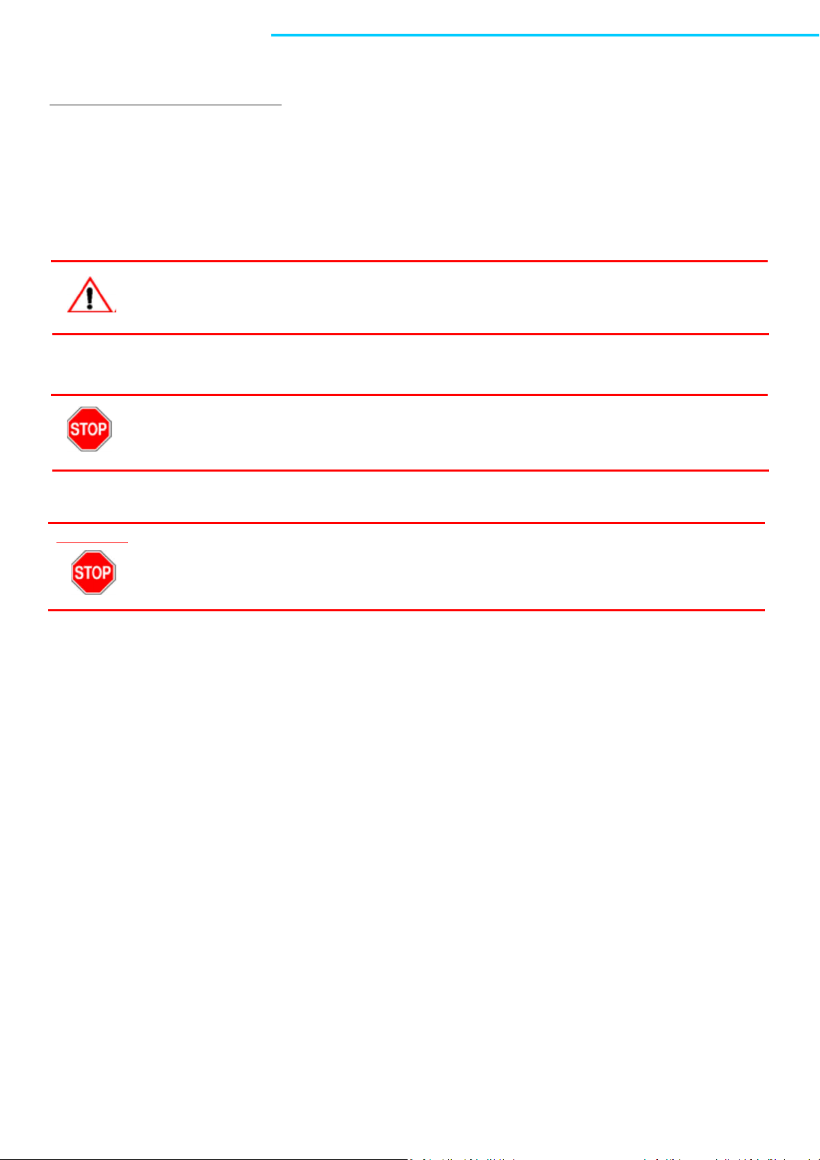
GPS for
radio
synchronization
Connection to CX XDP
port:
Connection to
LRC-508
Description:
LRC-508 transmits data between CX-508 via 2.4 GHz radio communication link.
It includes:
Ethernet communications link
and 48V power supply
external 7.4 dBi
antenna
5
Page 6

IMPORTANT
Whenever any connector is unused, put its connector protective cap in place.
6
Page 7
Description of radio protocol:
The LRC-508 uses a half-duplex transmission protocol with a Frequency Hopping Spread Spectrum (FHSS) method. A
mechanism of Listen Before Talk (LBT) is implemented to avoid radio collisions inside the LRC-508 network or with an
external radio network. Moreover, two security keys are configured to secure the LRC-508 network.
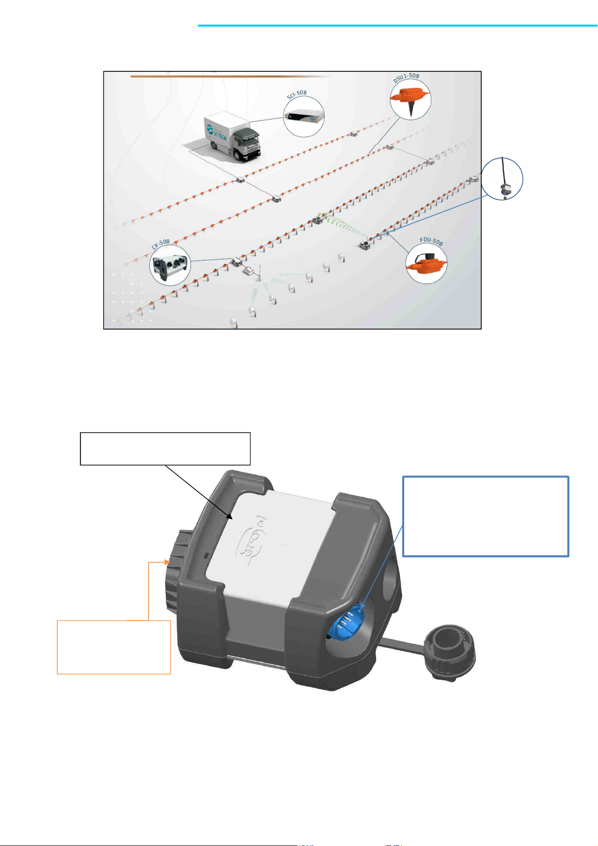
Frequency Hopping Spread Spectrum (FHSS)
The FHSS operates on a set of frequencies. It uses one frequency for a fixed period of time and then switches to
another channel. The next frequency is given by a pseudo-random sequence. In order to communicate, the
transmitter and the receiver have to us the same set of frequencies, the same frequency sequence defined by the
Frequency key. Moreover the LRC-508 has to be synchronized either by internal Gps or by IEEE1588 Ethernet
protocol.
Example of FHSS based on a set of 6 frequencies
Listen Before Talk (LBT)
The LBT is based on a Channel Control Access mechanism: the LRC measures the Received Signal Strength Indication
(RSSI) before beginning packet transmission. If the RSSI is too high, the media is said “busy” and the LRC-508
postpones the transmission for a random back off time.
7
Page 8

Deployment:
The LRC-508 can be connected to a CX-508 or a SCI-508:
Connection to CX-508:
The +7.4 dBi 2.4GHz antenna delivered in the kit is connected to LRC-508.
LRC-508 is mounted on the LRC mounting kit.
The LRC-508 is connected to XDP port of CX-508 with the external 2-m cable. Then the CX-508 automatically powers
LRC after its connection, to allow QC communication with the recording truck through a neighboring CX-508 located
in a connected spread.
A 15-m cable option exists either to mount the LRC-508 over an antenna mast.
To provide a protection against lightning, LRC-508 cable to CX-508 is grounded. Grounding is
performed by connecting metal part of the connector on CX-508 side to earth stake (provided with
CX) by using the green/yellow cable provided with LRC.
Connection to SCI-508:
The +7.4 dBi 2.4GHz antenna delivered in the kit is connected to LRC-508.
LRC-508 is mounted on the LRC mounting kit or to an antenna mast.
The LRC-508 is connected to XDP1 port of SCI-508 with the external 15-m cable. Then the SCI -508 automatically
powers LRC after its connection, to allow QC communication with a neighboring CX-508.
8
Page 9

AC Power Access:
NET Access:
the concentrator IP
XDP1:
- Communication between
Central Unit and Spread.
- DHCP server to deliver to
110-240Veff
1A – 0.5A
Port for connection to a
radio tool
CAUTION
It is highly recommended to disconnect LRC cable from SCI in case of impending lightning, in order
to protect personnel and equipment.
The grounding wing nut must be connected to the ground.
9
Page 10
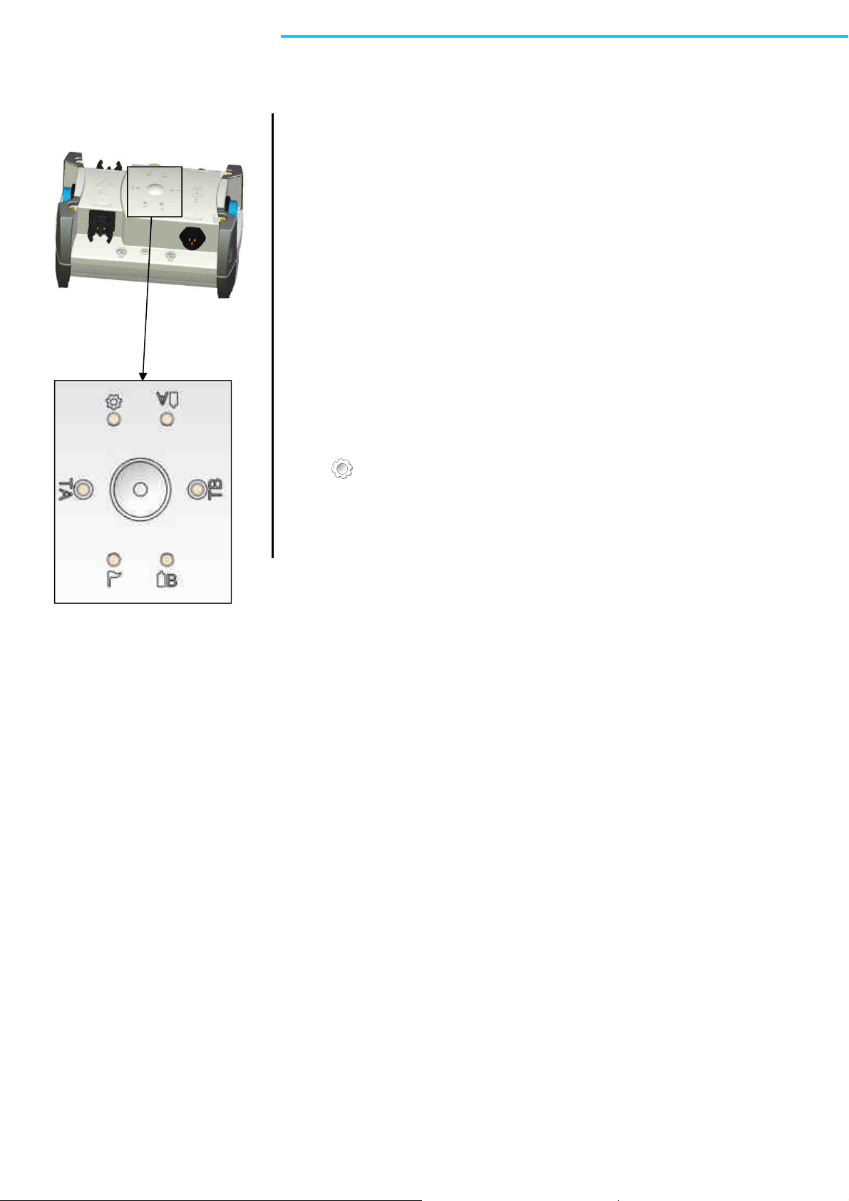
LEDs Function:
one yellow LED
dedicated for the
XDP port
lighted LRC is connected to this port
Configuring the LRC-508:
The User has to download a Crew Setup and a Radio Setup in the LRC-508.
Crew Setup Parameters:
The parameters are:
The GPS configuration:
•
list of allowed GNSS constellations (SBAS,QZSS,GALILEO,BEIDOU,GLONASS,GPS)
o
GPS Only is the default mode
o
GPS Only
o
GLONASS only
o
GPS+GLONASS+QZSS+SBAS
• Navigation model
o Fixed (Default mode)
o Pedestrian
10
Page 11

Radio Setup Parameters:
The radio parameters of LRC-508 are:
Radio data rates:
The following data rates are supported:
•
1200 bps
The packet duration is up to 400 ms. Moreover, the maximum radiated output power is limited to +10 dBm
in Europe countries, and +27dBm for USA and Canada.
• 100 kbps
The packet duration is up to 22 ms. Moreover, the maximum radiated output power is limited to +20 dBm in
Europe countries, and +27dBm for USA and Canada.
• 500 kbps
The packet duration is up to 8.5 ms. Moreover, the maximum radiated output power is limited to +20 dBm in
Europe countries, and +27dBm for USA and Canada.
Set Radio standards:
According to LRC versions, some units are CE (Europe) compliant only, and some are FCC (USA), IC (Canada) and CE
(Europe) compliant. Please refer to housing marking to see if relevant LRC is compliant with your local authorities.
In case where only CE marking is present, LRC should only be used in Europe, or other countries that accept
European standards. In that case following marking should be present:
In case where CE marking, FCCID as well as IC ID are present, LRC can be used in Europe, USA or Canada, or any other
country that accepts theses standards. In that case following marking should be present:
Use this menu to choose the appropriate maximum radiated output power for compliance with the local regulations
of the country in which the radio unit is to be used:
11
Page 12

• CE for Europe: +20 dBm max at 100 kbps and 500 kbps, +10 dBm max at 1200 bps
•
FCC / IC for USA and Canada: +27dBm max at 1200bps, 100kbps, 500kbps
Set Radio frequencies:
Use this menu to choose one of these sets of frequencies used in the Frequency Hopping Spread Spectrum (FHSS):
• 2405-2469 hopset : full 2.4GHz frequency band1
{2405.5 MHz; 2409.5 MHz;….; 2465.5; 2468.5 MHz } is the set of frequencies
• 2405-2469 hopset : full 2.4GHz frequency band2
{2406.5 MHz; 2410.5 MHz;….; 2466.5; 2467.5 MHz } is the set of frequencies
• 2405-2469 hopset : full 2.4GHz frequency band3
{2407.5 MHz; 2408.5 MHz; 2412.5 MHz ….; 2463.5; 2464.5 MHz } is the set of frequencies
• 2405-2438 hopset : half 2.4GHz frequency band1
{2405.5 MHz; 2407.5 MHz;….2437.5 MHz }
• 2422-2458 hopset : half 2.4GHz frequency band2
{2422.5 MHz; 2424.5 MHz;….2434.5 MHz; 2439.5 MHz; 2441.5 MHz;….2457.5 MHz }
• 2436-2469 hopset : half 2.4GHz frequency band3
{2436.5 MHz; 2438.5 MHz;….2468.5 MHz }
• 2405-2422 hopset : narrow 2.4GHz frequency band1
{2405.5 MHz; 2406.5 MHz;….2421.5 MHz }
• 2429-2446 hopset : narrow 2.4GHz frequency band2
{2429.5 MHz; 2430.5 MHz;….2445.5 MHz }
• 2452-2469 hopset : narrow 2.4GHz frequency band3
{2452.5 MHz; 2453.5 MHz;….2468.5 MHz }
The hopset has to be chosen to reduce interference with other radio equipments in 2.4 GHz frequency band.
For example, if a Wifi access point is configured at channel 6, the frequency band of the access point is 2426MHz2448MHz. Thus, the “Narrow Band 1” (2405-2422MHz) and “Narrow band3” (2452-2469MHz) hopsets have no
interference with this Wifi access point.
The following chart shows the Wifi channels in 2.4GHz frequency band:
Set Radio Security Keys :
Use the Frequency and the Synchro Word keys to secure its LRC-508 network.
Use the Frequency key to limit the interference with another LRC-508 network. The Frequency key defines a unique
frequency sequence. Two different Frequency keys define two frequency sequences, using the same set of 17
frequencies but correlation between the two different sequences is about null.
12
Page 13

Use the Synchro Word key to prevent connection to another LRC-508 network. The radio packets transmitted with a
Synchro Word key cannot be received by a LRC-508 configured with another Synchro Word key.
Frequency key = 1 (default) … 255
Synchro Word key = 1 (default) … 255
13
Page 14
Maintenance:
Calibration
The 1200-bps mode needs an oscillator of LRC-508 radio with a 1-ppm accuracy or better. To guarantee such
accuracy along the lifetime of the product, a calibration of oscillator frequency is necessary one time every year.
To do that, deploy LRC-508 in an open-sky environment and at about +25°C +/- 5°C. Launch an oscillator calibration
test, internal GPS Pulse-Per-Second is the reference during this test.
Other setups are allowed to do such calibration:
-
Indoor calibration and use a GNSS repeater
-
Connect LRC to a IEEE1588 network, with a Master Clock
IMPORTANT
Prior to connecting any plug, make sure there is no water inside connectors.
Electrostatic discharge:
Use the following guidelines to provide a static-free repair station that will preclude any ESD-related
damage to electronic circuits:
• All spare parts (circuit boards and ESD sensitive devices) should be stored and transported in staticshielding bags.
• Unless the repair station rests on a conductive floor, chairs or stools should rest on a grounded, rigidtype, static-dissipative floor mat.
• Use a static-dissipative table mat.
• Wear a static-control wrist strap or foot grounder.
• Provide common-point grounding for all conductive items (including personnel and soldering iron tip).
• To control the discharge rate and protect workers from electric shocks, both the table mat and wrist
strap should be grounded through a 1-MΩ resistor. The mat should be connected to the same earth
ground point as the wrist strap.
• Wear static-dissipative garments.
14
Page 15
Low Line plug
Signal Name
I/O type
Other signal
A +5V In
B GND
In
XDP plug
Signal Name
I/O type
Other signal
B XDP-MX1+
In-
Out XDP_P24
+24Vdc
A XDP-MX1
- In-Out XDP_P24
+24Vdc
XDP-MX2+
In-
Out XDP_M24
-24Vdc
XDP-MX2
- In-Out XDP_M24
-24Vdc
Resistance
between S and M =
Not connected
Resistance
between S and M =
Not connected
GROUND
Not connected
Not connected
Not connected
Not connected
Not connected
Not connected
Not connected
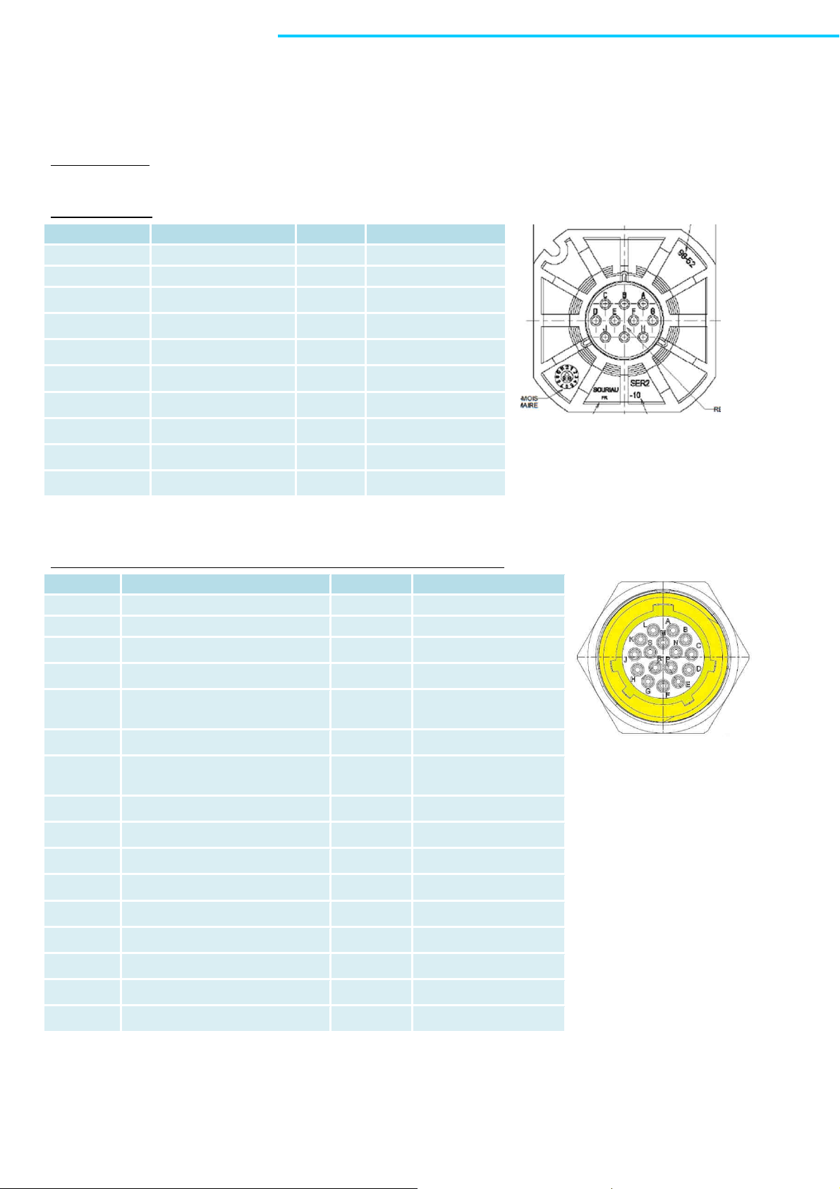
LRC-508 connectors:
RF connectors: straight bulkhead Jack panel seal
10-C connector:
C Not connected
D Not connected
E ETH_RX_N In +24Vdc
F ETH_RX_P In +24Vdc
G ETH_TX_N Out -24Vdc
H ETH_TX_P Out -24Vdc
I RS232_TX Out
J RS232_RX In
LRC cable is connected to CX XDP connector with the following pinout:
C
N
M
L
S
K
J
H
D
330 Ohm
330 Ohm
E
P
R
G
F
15
Page 16

Specifications:
Operating Voltage 48 Vdc
Current consumption 10mA (Typical current consumption)
Power consumption 0.5W (Typical power consumption)
0.7W (Max power consumption in CE configuration)
0.9W (Max power consumption in FCC configuration)
Radio data rates 1.2 – 100 – 500 kbps
Radio Frequency Characteristics:
Frequency band
Spreading method
Number of channels
Antenna gain +7.4 dBi typ.
Radiated output power
CE Mode at 1.2 kbps
CE Mode at 100 and 500 kbps
FCC Mode at 1.2kbps, 100kbps, and 500kbps
Supported GNSS Constellations GPS L1 C/A, GLONASS
Altitude functioning Up to 5000m
Weight (LRC with antenna) 1.20kg (2.64lbs)
Operating Temperatures -40°C to +70°C (-40°F to +158°F)
Operating Environment IP68
2405 – 2469 MHz
FHSS
17
+7 dBm typ, +10 dBm max
+17 dBm typ, +20 dBm max
+24 dBm typ, +27dBm max
16
Page 17

Regulatory Information:
USA
This device complies with Part 15 of the FCC Rules. Operation is subject to the following two conditions:
(1) This device may not cause harmful interference, and
(2) This device must accept any interference received, including interference that may cause undesired operation.
Changes or modifications not expressly approved by the party responsible for compliance could void the user's authority to
operate the equipment.
WARNING
This device must be professionally installed.
This equipment has been tested and found to comply with the limits for a Class B digital device, pursuant to part 15 of the FCC
Rules. These limits are designed to provide reasonable protection against harmful interference in a residential installation.
This equipment generates, uses, and can radiate radio frequency energy and, if not installed and used in accordance with the
instructions, may cause harmful interference to radio communications. However, there is no guarantee that interference will not
occur in a particular installation. If this equipment does cause harmful interference to radio or television reception, which can be
determined by turning the equipment off and on, the user is encouraged to try to correct the interference by one or more of the
following measures:
— Reorient or relocate the receiving antenna.
— Increase the separation between the equipment and receiver.
— Connect the equipment into an outlet on a circuit different from that to which the receiver is connected.
— Consult the dealer or an experienced radio/TV technician for help
This equipment complies with FCC’s radiation exposure limits set forth for an uncontrolled environment under the following
conditions:
1. This equipment should be installed and operated such that a minimum separation distance of 20cm is
maintained between the radiator (antenna) and user’s/nearby person’s body at all times.
2. This transmitter must not be co-located or operating in conjunction with any other antenna or transmitter.
Canada
This device complies with Industry Canada license-exempt RSS standard(s). Operation is subject to the following two conditions:
(1) This device may not cause interference, and
(2) This device must accept any interference, including interference that may cause undesired operation.
Le présent appareil est conforme aux CNR d’Industrie Canada applicables aux appareils radio exempts de licence. L’exploitation
est autorisée aux deux conditions suivantes :
(1) l’appareil ne doit pas produire de brouillage, et
(2) l’utilisateur de l’appareil doit accepter tout brouillage radioélectrique subi, même si le brouillage est susceptible d’en
compromettre le fonctionnement.
Under Industry Canada regulations, this radio transmitter may only operate using an antenna of a type and maximum (or lesser)
gain approved for the transmitter by Industry Canada. To reduce potential radio interference to other users, that antenna type
and its gain should be so chosen that the equivalent isotropically radiated power (e.i.r.p.) is not more than that necessary for
successful communication.
This radio transmitter (1317A-0104A) has been approved by Industry Canada to operate with the antenna types listed below with
the maximum permissible gain and required antenna impedance for each antenna type indicated. Antenna types not included in
this list, having a gain greater than the maximum gain indicated for that type, are strictly prohibited for use with the device.
17
Page 18

Manufacturer
Reference
Gain
Impedance
L-COM
HG2408UR
-NM
+7.4dBi
50 Ohms
NCG SFR-245SPR
-R
+7.4dBi
50 Ohms
(1)
Europe:
Conforms to the essential requirements of the following EEC directives:
R&TTE 1999/5/CE
EMC 2004/108/CE
LV 2006/95/CE
WARNING
The LRC-508 meets the reference level set by the 1999/519/CE recommendation:
Electric field strength in the far field of a radio frequency point source is calculated as follows:
√
With: E = Electric filed in V/m
P = Maximum average transmit power capability of the radio, in W
G = total Tx gain as a factor, converted from dB
D = distance from the point source, in m
30 ∗ ∗
band P G E
2.4GHz 0.1W (+20dBm) 5.5 (7.4dBi) 61V/m 0.07m 0.2m
(1)
reference level of the table 2 of the 1999/519/CE
d Recommanded distance
18
 Loading...