

Serak-tech VNCF User Manual
USER'S MANUAL
VNCF

2
CONTENT
Purpose
Delivery set
Basic technical data
Fan designation key
Safety requirements
Fan structure
Mounting and preparation to operation
Mounting options
Mounting sequence
Fan electrical connection
Wiring diagrams
Servicing and maintenance
Storage rules
Manufacturer's warranty
Acceptance certificate
Warranty card
р. 3
р. 3
р. 3
р. 4
р. 5
р. 7
р. 8
р. 8
р. 10
р. 12
р. 14
р. 23
р. 23
р. 25
р. 27
р. 27
VNCF

3
PURPOSE
DELIVERY
SET
BASIC
TECHNICAL
DATA
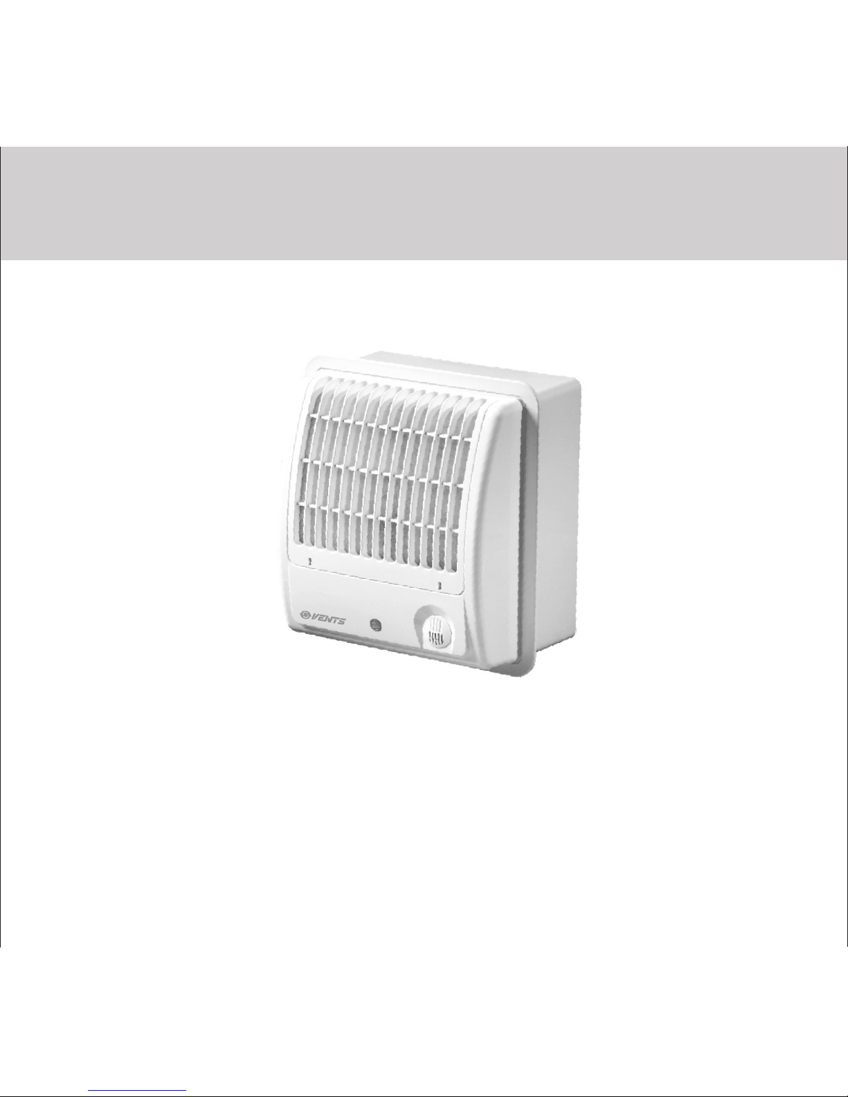
The centrifugal fan VNCF, further referred as the fan, is designed for exhaust
ventilation of living spaces, offices, shops, kitchens, WCs and other residential and
public premises heated during winter time.
The fan is suitable for ceiling or wall mounting.
The operating medium must not contain any dust or other solid particles, sticky
3
substances and fibrous materials concentrated above 100 mg/m.
The delivery set comprises:
- fan - 1 pce;
- decorative front panel - 1 pce;
- dowels and screws - 4 sets;*
- user's manual - 1 pce;
- packing box - 1 pce;
The delivery set for the CF 100 turbo comprises 3 sets.
The fan is designed for connecting to single-phase AC power supply network with
voltage 220-240 V and 50 Hz frequency or 12 V voltage and 50 Hz frequency for
low-voltage 12 V modifications.
The fan is designed for operation in the temperature range between 0°C and +45°C.
The fan does not cause interference with radio-, TV- or video- equipment.
The minimum service life is 5 years.
VNCF

4
VNCХХХ 100 X X
Fan and filter type
C - centrifugal
F - synthetic filter
FA - aluminium filter
V - electrical switch modification
T - timer modification
TH - timer and humidity sensor modification
TP - timer and motion sensor modification
Designation key example:
VENTS CF 100 VTH turbo - CF series fan, sincludes a synthetic filter, flange diameter 100 mm, equipped with
an electric switch, timer, humidity sensor and single-phase high-powered motor.
100 - exhaust pipe diameter [mm]
Number of speeds
_ - the fan has one speed by default
3 - three-speed fan
Motor modifications
turbo - high-powered motor
12 - low-voltage motor 12V/50 Hz
FAN
DESIGNATION
KEY
VNCF

5
SAFETY
REQUIREMENTS
Protection rating against access to dangerous parts and water penetration:
- IP 24 for fans with a synthetic filter;
- IP 34 for fans with aluminium filter.
Disconnect the fan from power mains prior to all connection, adjustment, servicing and
repair works.
Only the qualified electricians authorized for independent electrical works at electrical
installations with the voltage up to 1000 V are allowed for servicing and maintenance of
the fan after reading this manual.
Single-phase power network used for connection of the device must be in compliance
with the acting norms and standards. The fixed wiring system must be equipped with an
automatic circuit breaker.
The fan shall be connected through the switch integrated into fixed wiring system.
Keep the clearance between the dead contacts not less than 3 mm for all poles.
Before installation works make sure that the fan impeller, casing and grille are free of
any visible damages and that the casing has no foreign objects inside that can damage
the impeller blades.
Misuse of the device, any unauthorized alteration or modification is prohibited.
The device is not designed to be used by children, physically or mentally disabled
persons, persons with sensory disorder, persons with no appropriate life experience
and/or expertise unless they are properly instructed about the device use or supervised
by the person in charge for their safety.
Keep the device out of reach of children or supervise the children to avoid their playing
with the device.
VNCF
6
Don't use the fan for operation in explosive dust-air mixture environment.
Do not operate the fan beyond the specified operating temperature conditions as well as
in environments containing aggressive mixtures.
Take precautions to prevent penetration of smoke, carbon monoxide and other flame
products into the room through open chimney flues or other fire-protection devices.
Take also measures to disable gas back draft in case of using gas or open flame devices.
The operating medium must not contain any dust or other solid particles, sticky
substances and fibrous materials.
The fan operation in the environment containing flammable substances or vapours such
as spirit, gasoline, insecticides etc. is not allowed.
Do not close or block unit inlet and outlet vents to ensure the most effective air passage.
Do not sit or put objects on the unit.
The owner of the goods should follow the requirements set forth herein.
PROHIBITED: PROHIBITED:
!
Disconnect the fan from power mains prior to all installation, connection, adjustment and
repair works.
!
WARNING
WARNING
VNCF
7
FAN
STRUCTURE
1
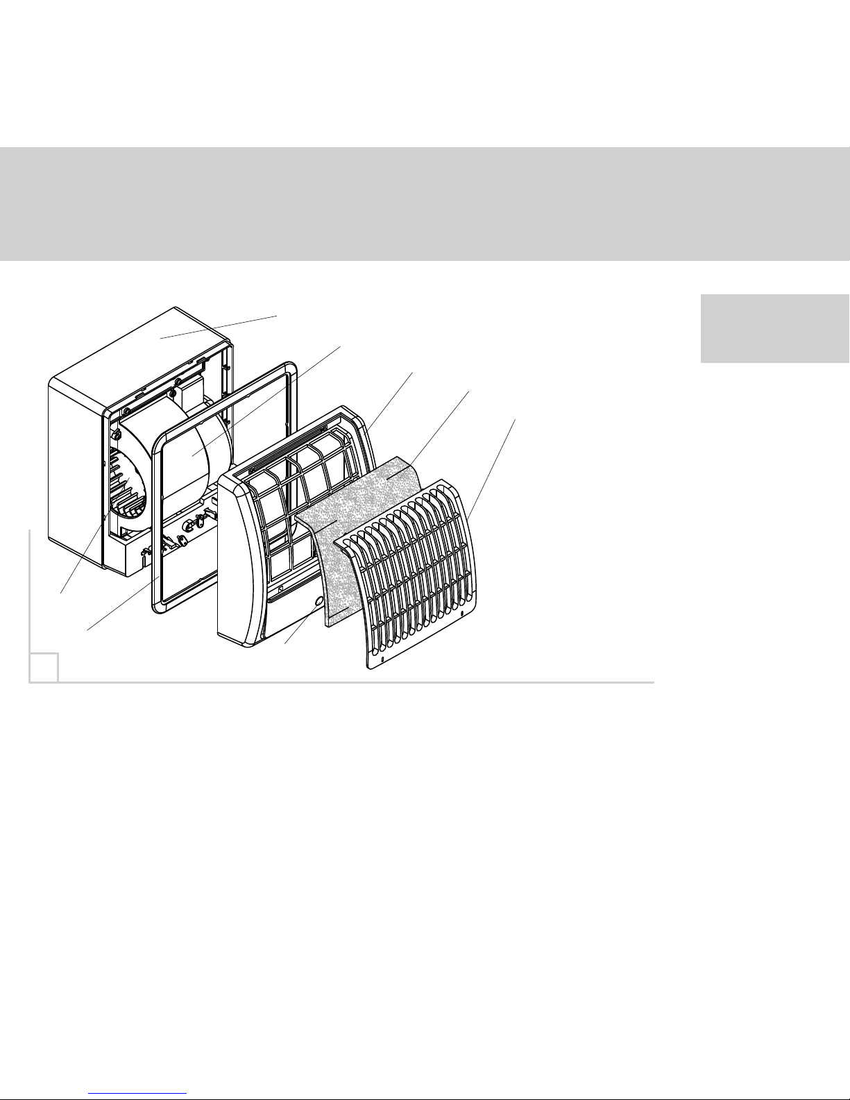
The VNCF fan (fig, 1) consists of the casing 1 with the motor and impeller 6
assembled inside of the casing. The impeller 6 is located in the scroll casing 7.
The frame 5 is locked inside the casing 1 and functions as a stopper in case of
Through-the wall mounting.
The swivel cover 2 with the fixed grille 4 is attached to the casing.
The filter 3 is inserted into a space between the cover and the grille.
The back valve is installed on the fan back side in the exhaust pipe.
The LED lamp 8 indicates the fan ON/OFF operation.
1 - casing,
2 - removable cover,
3 - filter,
4 - grille,
5 - decorative frame,
6 - runner,
7 - scroll casing,
8 - indicating lamp.
1
6
5
7
2
3
8
4
VNCF
8
MOUNTING AND
PREPARATION
TO OPERATION
MOUNTING
OPTIONS
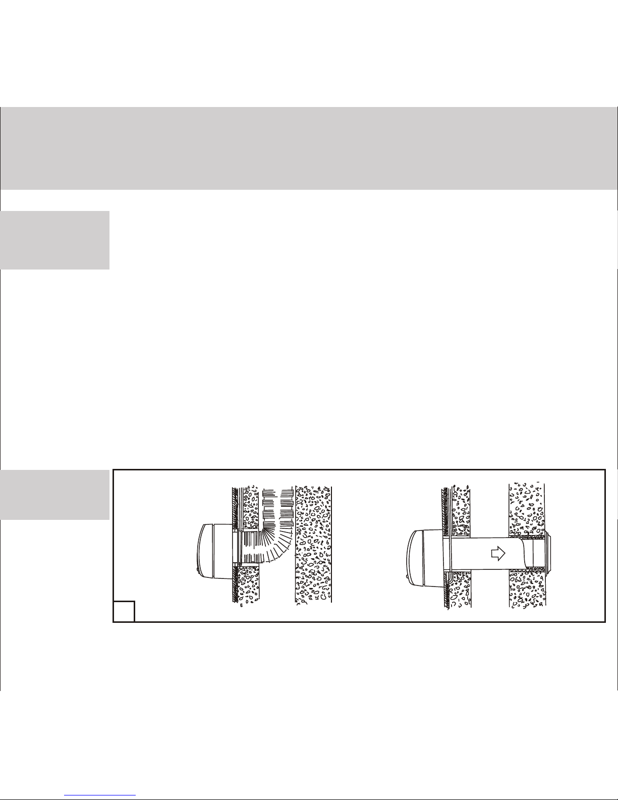
The VNCF fans are suitable for wall and ceiling mounting.
The mounting options are shown in fig. 2-7.
In case of wall mounting (fig. 2) the fan is fastened to the wall with self-tapping screws
included into delivery set. In case of mounting as shown in fig. 3 the fan is mounted by
means of the fastening brackets.*
Bend the fastening brackets for the required length to suit mounting requirements.
The mounting option in fig. 4 provides the fan installation on the construction foam.
The mounting option in fig. 5 provides the fan installation of the fan in a specially designed
recess. The fan is mounted to ceiling either with fastening brackets (fig.6) or inserted into
a specially designed recess (fig.7).
The wall mounting sequence is shown in fig. 8-10.
The built-in wall mounting sequence is shown in fig. 11 and the ceiling built-in mounting
sequence is shown in fig. 12.
* The basic delivery set does not include fastening brackets.
2
Wall mounting
VNCF

9
3
4
5
Flush wall
mounting with
fastening
brackets
Flush wall
mounting with
construction
foam
Built-in recess
mounting
1
~
85
1
~
85
0
~2
0
0
~2
0
1
0
~
1
1
0
~
1
-
2
70
7
-
2
70
7
VNCF
 Loading...