

Page 1
E R A IS
GATE AUTOMATION DIVISION
MT/B4 - SR 03.B4 - MOTOR FOR SWING GATES UP TO 4 METERS - 300Kg- 230 V~
MT/C4 - SR 03.C4 - MOTOR FOR SWING GATES UP TO 4 METERS - 300Kg- 24 Vdc
Page 1/6
INSTALLATION MANUAL
MT/B4-C4 I E
!
Thank you for choosing a SERAI ELETTRONICA product, which we are confident will perform to your requirements.
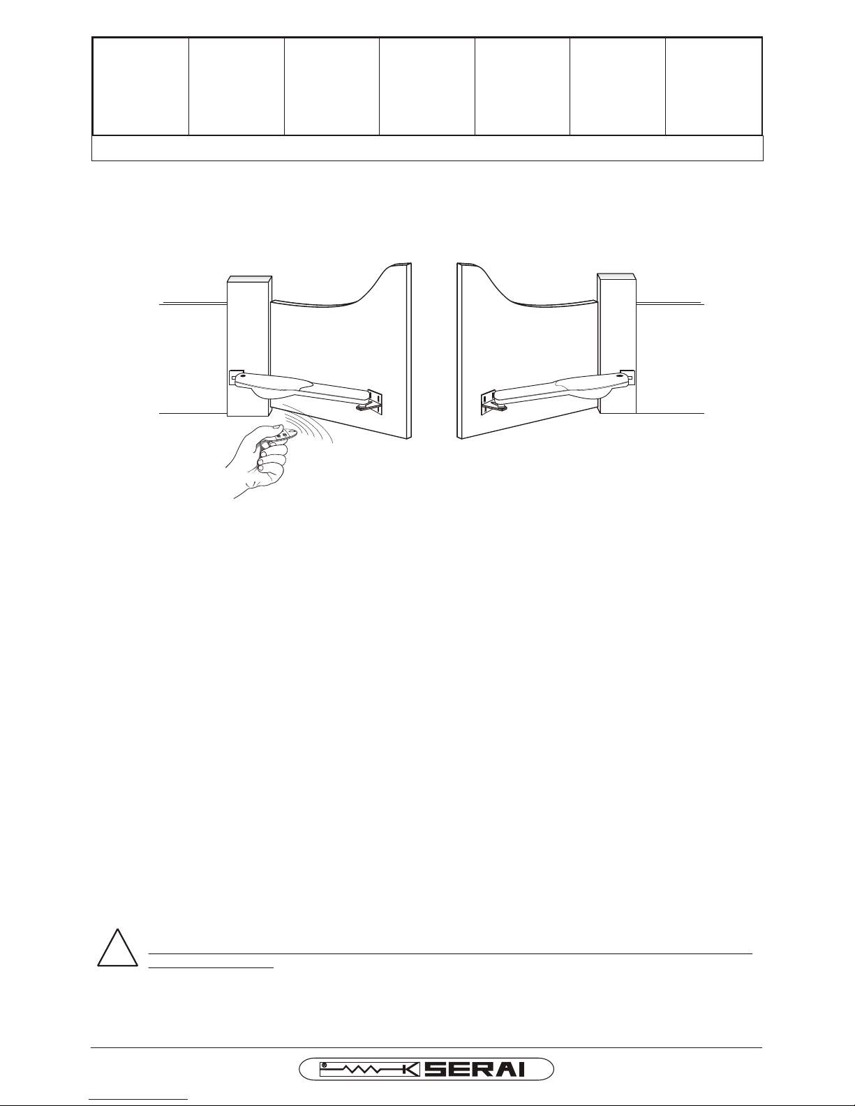
Please be advised that you are about to fit a system classified as “a power-operated drive designed to move automatic gates and doors in commercial or residential buildings accessed by vehicles and persons”, and as such, the system must be
considered potentially hazardous. By law, you are responsible for rendering this equipment as “safe” as is reasonably pos-
sible.
Installation and maintenance of equipment of this kind must therefore be carried out by skilled, qualified and trained
personnel, working in a professional manner, as provided for by law n. 46/90 and any subsequent amendments and
supplements. The law in question prohibits the construction of these types of systems by non-qualified personnel.
SERAI manufacturing complies with the following legislation:
Applicable directives for the CE marking :
Machines: 98/37/EEC
Low Voltage: 73/23/EEC
Electromagnetic Compatibility: 89/336/EEC
General applicable standards:
Electrical Safety: IEC EN60335-1 + IEC EN60335-2-103
Electromagnetic Compatibility - Emissions: CEI EN61000-6-3
Electromagnetic Compatibility - Immunity: CEI EN61000-6-
Apart from the legislation mentioned above, you are also reminded to comply with the following standards during the
installation phase.
General applicable standards:
Safety of electrical systems in non-specialised environments: CEI 64-8
Specific product standards applicable:
Safety in the use of power-operated doors - requirements: UNI EN12453
Safety in the use of power-operated doors - testing methods: UNI EN12445
SERAI products enable users to build systems which comply with these standards. This is extremely important as
THE INSTALLER IS LIABLE FOR THE SYSTEM AND FOR ENSURING ITS OPERATION COMPLIES WITH
LEGAL PROVISIONS.
This handbook must be read in full before proceeding with the installation of the various parts of the system.
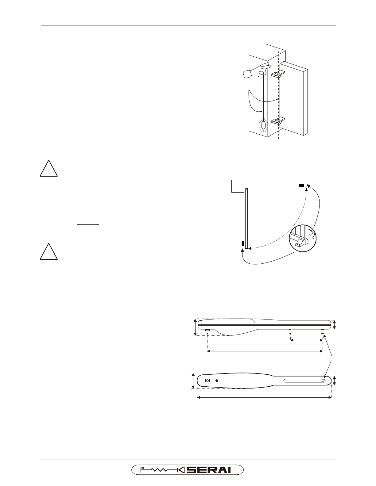
The motor is equipped with adjustable internal mechanical stops. In any event, the installer must position the
mechanical end stops for gate opening and closing for system safety purposes.
SINCE 1965
Page 2
MT/B4-C4 I E
Page 2/6
GATE
OPENING
AND CLOSING
END STOP
LATERAL VIEW
VIEW FROM BELOW
Fig. 3
Fig. 2
Fig. 1
280mm
735mm
70mm
130mm
90mm
850mm
135mm
PM
!
!
SINCE 1965
BEFORE INSTALLING THE MOTORS
1- Ensure perfect right angles of the gate hinges to enable
totally smooth and balanced swing gate movement.
Otherwise the motor may be damaged when subject to
much higher levels of resistance with respect to the those specified for intended use.
2- The MT/C2 motor is equipped with internal mecha-
nical stops adjustable by means of a special screw
(see adjustment of internal mechanical stops) to
enable adjustment of the gate closing and opening
stop points. In any event, the installer must position
the mechanical end stops for gate opening and closing
for system safety purposes - see Fig. 2 -.
3- The installation of the mechanical end
stops for gate opening and closing is necessary for system safety purposes.
4- The motor is supplied with the mobile pin (PM) - Fig. 3 -
in the correct position for installation. However, ensure
that the distance of the mobile pin from the rear connection point is: 735 mm.
Any distance greater than the above can cause shutdown of the motor shortly before the
gate reaches the closing end stop; any distance less than the above will cause a smaller opening angle than required.
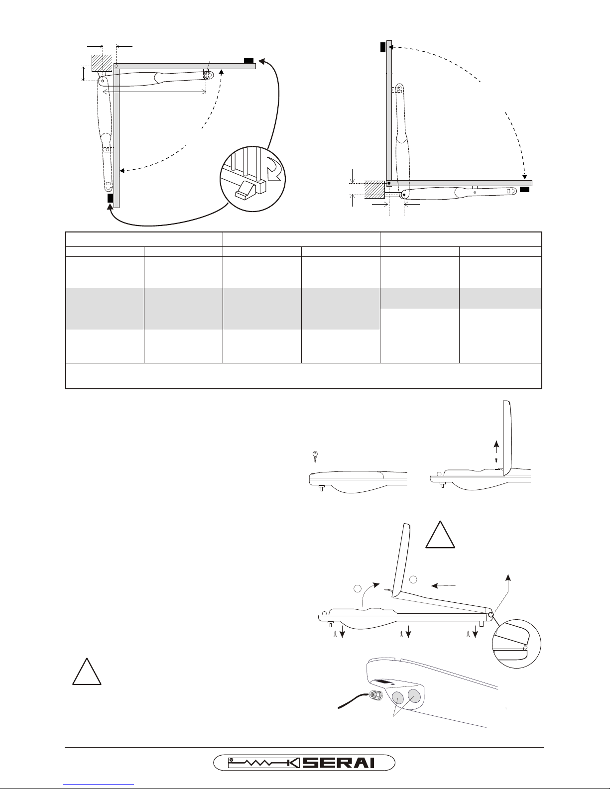
5) Choose the opening angle and calculate the
distances B, C (see Fig. 4 Fig. 5 and table) for
positioning of brackets. The values in the grey band
are recommended. The brackets can be resized
(shortened or lengthened) according to assembly
requirements, taking care to observe distances B
and C.
N.B. In the case of outward opening, the overall working
area of the gate is reduced due to the dimensions of the
motors. In this case installation of the motors on the upper
section of the gate is recommended.
IMPORTANT: failure to observe distances B and C
specified in the table will mean that the gate starts
movement suddenly with excessive oscillations,
which could lead to damage to the brackets and motor.
Page 3
Page 3/6
MT/B4-C4 I E
BRACKET POSITIONING FOR INWARD OPENING
BRACKET POSITIONING FOR OUTWARD OPENING
C
PM
INWARD OPENING
OUTWARD OPENING
PM
B
C
735 mm
B
Fig. 5
Fig. 4
ELECTRICAL CONNECTION
SET-UP
6- Before installing the motor, open the rear section af-
ter releasing by means of the safety key supplied –
Fig. 6 -
7- Loosen the internal screw by means of a Phillips
screwdriver
-Fig. 7 -. Raise the top casing by tilting it by a couple of
degrees, then pull out horizontally. - Fig. 8 -
8- Remove the lower casing by loosening the 3 lower
screws.
- Fig. 8 -
9- The rear wall of the lower casing has a blank-out sec-
tion for cable routing. Fix the cable using a cable
clamp PG11 - Fig. 9 -
Use an outdoor cable that remains flexible
at low temperatures.
OPENING ANGLE 90° OPENING ANGLE 100° OPENING ANGLE 110°
B C B C B C
180 105
170 115 160 95
160 118 150 105 130 120
150 130 140 120 120 130
140 140 130 130 110 140
130 150 120 135 110 150
120 160 110 145
110 167 100 155
100 176 90 165
90 185
Warning: to ensure correct gate movement, use values in the shaded band.
The gate opening (or closing) time varies according to the selected values B and C.
Fig. 6
Fig. 7
Fig. 8
!
WARNING:
if inclined
excessively, the
connector tooth
may break.
Fig. 9
1
2
!
PUNCH-OUT WALLS
SINCE 1965
Page 4
Page 4 /6
MT/B4-C4 I E
!
Advice for wiring up in non-specialised environments.
1. Fit an omnipolar switch upstream of the system, choosing one with a gap of at least 3mm between the contacts. Or,
alternatively, use a 10A thermal magnetic circuit breaker switch.
2. Make all types of connection with the system disconnected from the power, i.e. with the main switch set to OFF
(symbol “0”). The control unit, in particular, must never be connected to the power supply either during the wiring up,
or when fitting any expansion cards.
3. The following cables must be used for installation of the system:
2 2
- for the motor power supplies: 4x1.5mm version 230V, 2x2,5mm version 24V,
2
- for the battery and electric lock power supplies: minimum 2.5 mm
22
- for the control unit power supplies: 1.5mm section for lengths of up to 19m, 2.5mm section for lengths of up to
31m,
22
- for the flashing light: 0.75mm section for lengths of up to 3m, 1.5mm section for lengths of up to 19m,
- for the low voltage and current lines, (e.g. for the photocells, control buttons, electromechanical key, sensitive
22
edges and other safety devices: 0.5mm section for lengths of up to 50m, 0.75mm section for lengths of up to
100m.
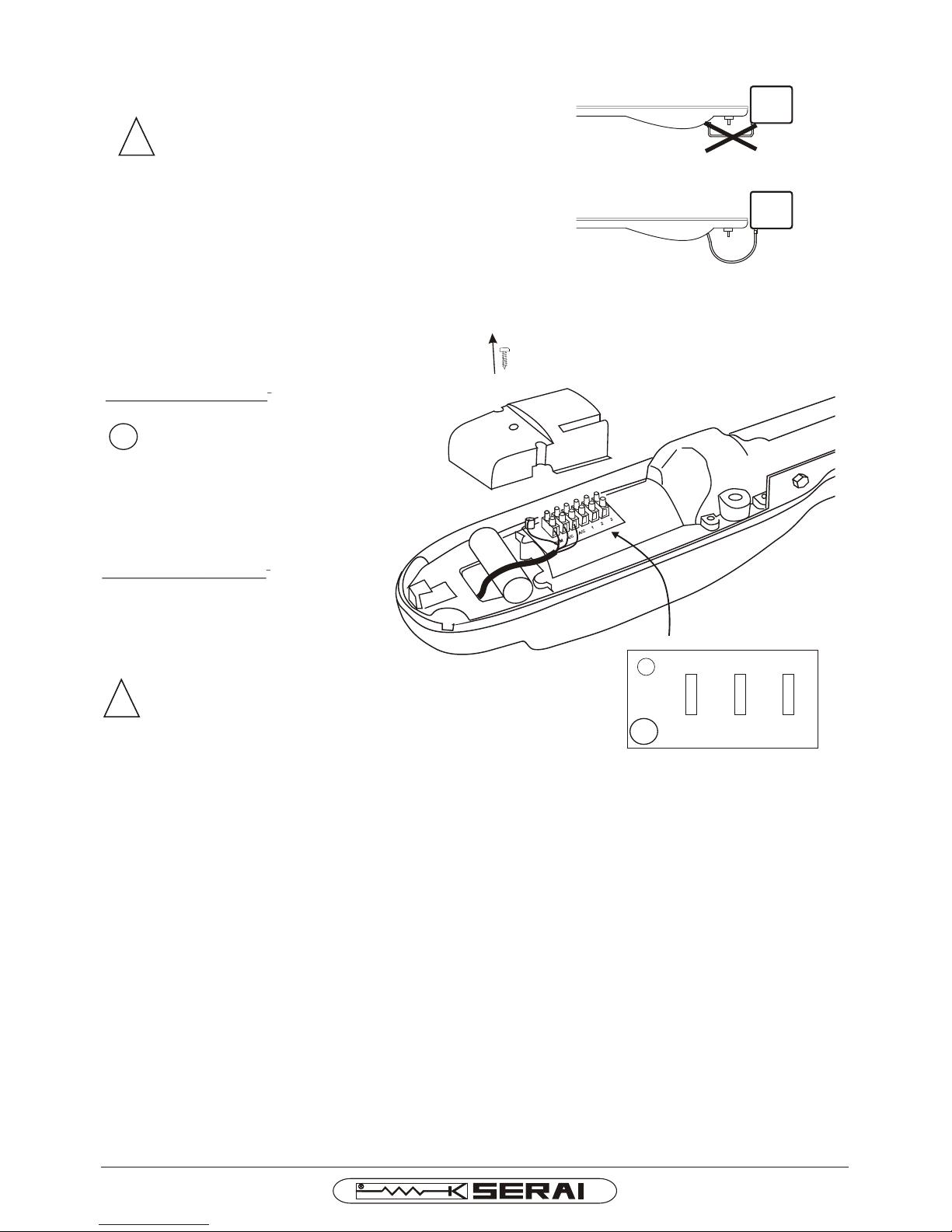
!
WARNING: never make sharp bends in the
cable on exit from the motors - Fig. 10 - as
this may cause damage and constitute a
hazard over time.
12- Refit the terminal board cover.
11- Remove the terminal board cover and proceed with elec-
trical connections. - Fig. 11 -
10- Refit the lower casing by securing the screws
|
__
_
_
Fig. 10
NO
YES
Terminal board cover
|
__
_
_
COM A/C A/C 1 2 3
WARNING:
On versions MT/B4 - at 230V~ - the capacitor
is pre-wired internally.
FOR MOTOR 230V~
2
Use a cable of 4x1,5mm with the sequence:
Earth connection (MT/B4 only)
COM MT/B4 motor common
A/C MT/B4 open/close
A/C MT/B4 open/close
FOR MOTOR MT/C4 24Vdc
2
Use a cable of 2x2,5mm with the sequence:
2 MT/C4 open/close
3 MT/C4 open/close
Fig. 11
SINCE 1965
Page 5
Page 5/6
MT/B4-C4 I E
PROVISIONAL MOTOR INSTALLATION
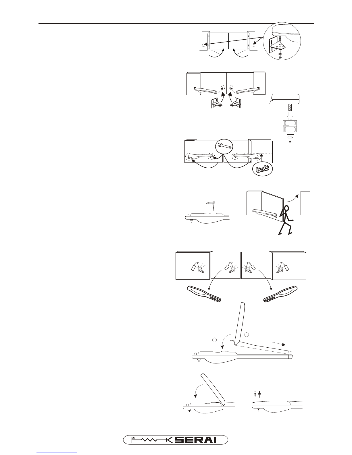
13-Close the gate completely. Provisionally fix the rear
bracket - Fig. 12 - onto the gate post by welding or by
means of screws + plugs, observing distances B and
C. Provisionally fix the motor to the rear bracket using
the central hole. As shown in Fig. 12
143-Move the motor up against the closed leaf to deter-
mine the front bracket welding point. Move the motor
away from the leaf.
Provisionally fix the front bracket to the gate, observing the distance and travel limits of the mobile pin.
Insert the mobile pin on the bushing and the latter on
the front bracket - Fig. 13 A - then provisionally secure
by means of the nut and washer.
15-Ensure that the motor is levelled. - Fig. 14 -
16-Release the motor - Fig. 15 - using the special key fi-
xed to the terminal board cover. Check that movement
is smooth - Fig. 16 -. Return the gate to the closed position and block the motor using the special key fixed
to the terminal board cover - Fig. 15 -.
FINAL INSTALLATION
17-Remove the motor from the brackets. Weld the front
bracket in its final position. Fix the rear bracket in its
final position. - Fig. 17 -
18-Refit the motor. Any differences in values B and C can
be compensated for using the 5 holes on the rear bracket. - Fig. 12 -
19-Refit the upper casing, keeping the front section
slightly inclined to engage the connector tooth and then
lower and secure by means of the rear screw.
- Fig. 18-
20-Reclose the rear cover and remove the safety key.
- Fig. 19 and 20 -
Fig. 12
FRONT BRACKET
Fig. 13
REAR
BRACKET
Fig. 17
Fig. 14
!!
Bracket
Bushing
Washer
Nut
Fig. 20
Fig. 19
Fig. 18
1
2
Fig. 13 A
Fig. 16
Fig. 15
SINCE 1965
Page 6

MOVING THE GATE MANUALLY IN THE EVENT
OF A POWER FAILURE
- Open the rear section after releasing by means of the
safety key supplied. - Fig. 25 -.
- Release the motor by using the internal key secured to
the terminal board cover - Fig 26 -; manual movement of
the gate is now possible - Fig. 27 -.
- To restore the locked status (in any position) simply rotate the internal key in the opposite direction.
ADJUSTMENT OF INTERNAL MECHANICAL STOPS
- Open the rear section after releasing by means of the safety key supplied. - Fig. 21-
- Loosen the internal screw by means of a Phillips screwdriver. 22. Raise the top casing by tilting it by a couple of
degrees, then pull out horizontally. - Fig. 24 -
- Using a 13 mm wrench, set the two front (closing) mechanical stops and rear (opening) stops in the required position. - Fig. 23 -
MOTOR FORCE ADJUSTMENT
Adjustment of motor force for the version MT/B4 at 230V~ is by variation of the power supply voltage, for example
using the control unit SERAI CR/41, and by variation of the current control on the version MT/C4 at 24Vdc, for
example using the control unit SERAI CR/39.
In any event, installation must be in full observance with current standards governing power-operated gates;
remember that the installer is responsible for the system and operation in compliance with
standards.
Fig. 26
Fig. 25
Fig. 27
Fig. 21
Fig. 22
Fig. 24
!
WARNING: if inclined
excessively, the
connector tooth may
break.
1
2
Fig. 23
MOTOR TECHNICAL SPECIFICATIONS
MT/B4-C4 I E 02 06 080529 - A4Vf/r -IS MTB4-IS-E
MT/B4 MT/C4
Max. leaf length
Max. leaf weight
Power supply
Absorption
Power
Angular speed
Opening time
4,00
300 Kg
230 V~ ± 10% 24Vdc ±25%
50/60Hz
1,5A 1,5A
110W 110W
0,084 rad/s
20s
Max. thrust
Max. torque on leaf
Force adjustment
Protection rating
Temperature
Dimensions
Weight
- without brackets -
1600N 1600N
200Nm 200Nm
variation of power current
supply voltage control
IP55
-20°C ÷ +60°C
850 x 130 x 135 mm
9,5 Kg 8,5Kg
MT/B4 MT/C4
ELETTRONICA PADOVA
I
SINCE 1965
MADE IN ITALY
VIA ENRICO FERMI, 22
35020 LEGNARO - PADOVA
I T A L I A
PHONE +39 049 79 08 58
FAX +39 049 88 30 529
E-MAIL [email protected]
WEB www.serai.com
TERMS OF GUARANTEE
The company reserves the right to make modifications to the equipment without prior notice thereof. SERAI products are covered by a standard guarantee with a term of 24 months.
Coverage starts on the date on which the tax document constituting proof of purchase is issued and guarantee services shall be provided on the company's premises at Legnaro - PD or at the Authorised Service Centres. Carriage costs shall be borne by the Customer.
CE CONFORMITY DECLARATION
SERAI spa declares that the product MT/B4, MT/C4 has been desifned and manufactured according to the above mentioned directives and standards
WEEE DIRECTIVE 2002/96/EC
This appliance was manufactured after 13/08/2005. To protect the environment: when the equipment is no longer needed, take it to a special WEEE (Waste Electric and
Electronic Equipment) collection centre. Do not dispose of it with normal household waste.
 Loading...