

Page 1
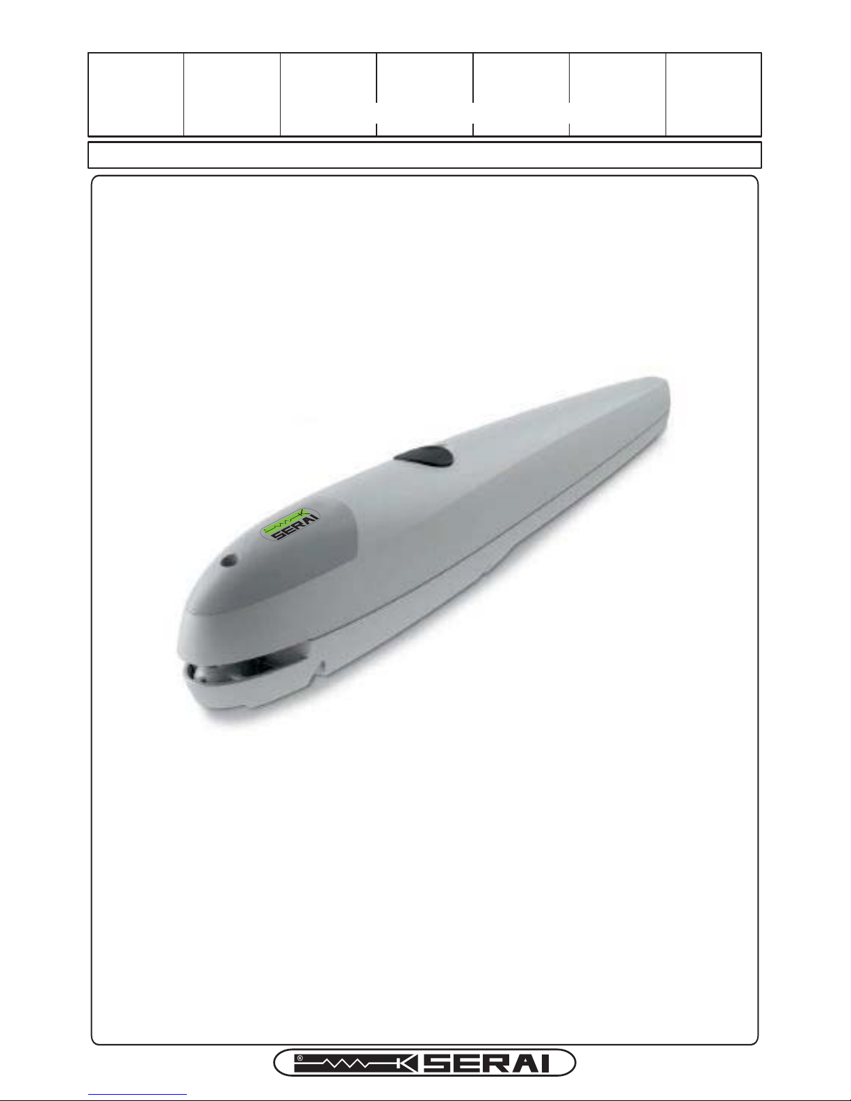
MT/BZERO
03.B0
OERATORFORSWING GATESUPTO2m-200Kg
ERA IS
Divisione Apricancelli
DAL 1965
MT/BZERO EN V01 F12 20170127
A5VL 40g/mq - IS MT/B0/24-E
Page 2
1A - WARNINGS
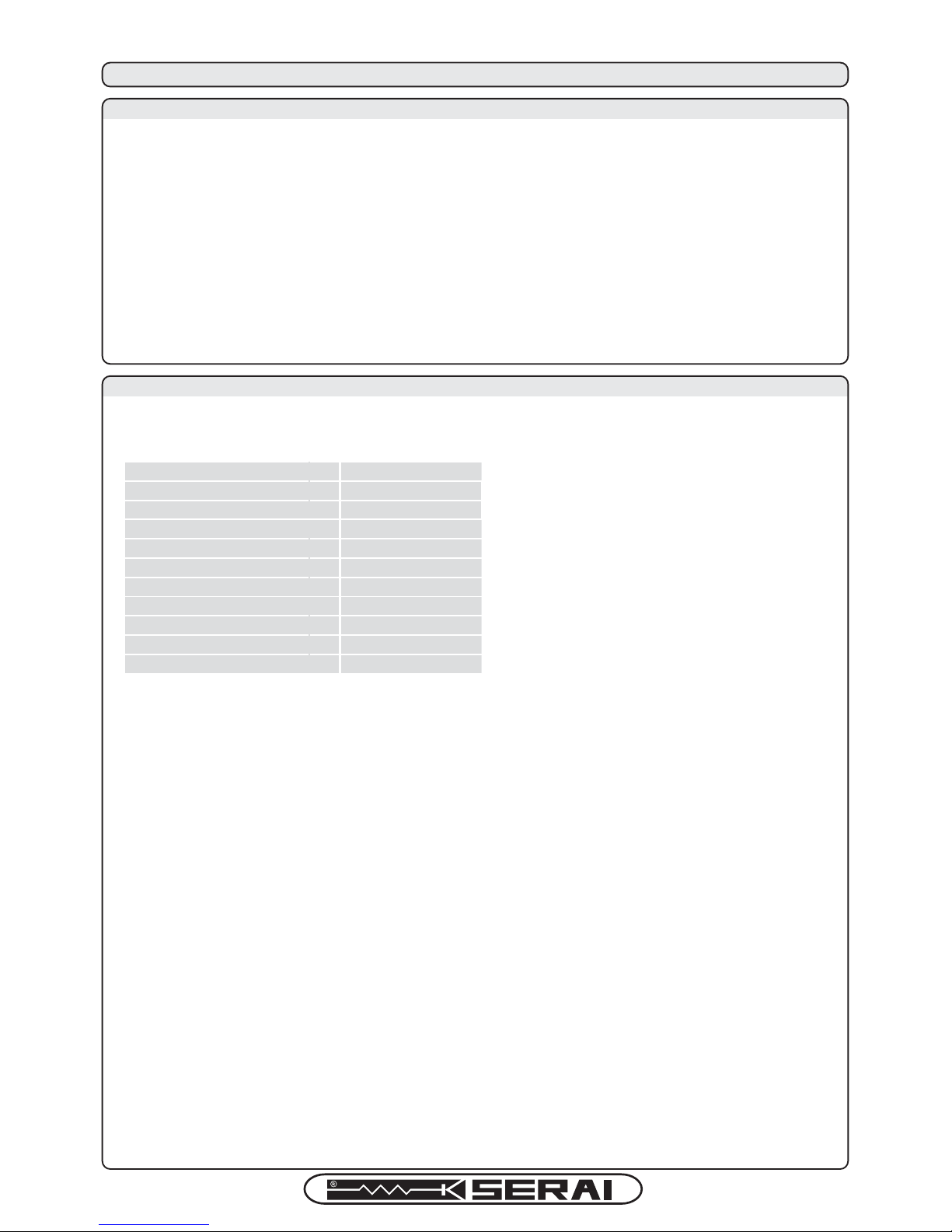
1B - TECHNICAL DATA
1 - GENERAL DESCRIPTION
Before proceeding with the installation check that all the safety conditions are observeded in full compliance with laws
rules and regulations. Unfulfilment of the below listed directions will release the SERAI srl, from any responsibility for
damage caused to people or things.
- When opening the packaging, verify the integrity of all the product parts.
- In case of functioning anomalies, power off immediately the operator, disconnect it from all power sources and manually
operate the gate until the failure has been individuated and repaired by qualified personnel.
- Do not modify the product in any part, follow the instruction manual indications.
- Dismantling an repairing of the unit is allowed exclusively to authorized and qualified personnel.
- Avoid to install the operator close to direct heating sources or in contact with liquid substances.
- Wire the operator to the automation system with the appropriate power supply cables (3 wires cable, min. 0.75mm2).
- To optimize the functioning of the automation, use only SERAI accessories.
- Installing, testing and first functioning have to observe the laws in force.
- Disposal of waste material has to observe local regulations.
- The gear-motor doesn’t require any particular maintenance because it is provided with a permament lubrification system.
Operator supply
7ED 24
Power
8
80
Speed
NT
Travel
NN
Protection degree
*1
44
Operator weight
LH
6
Max. lenght of the leaf
N
Max. weight of the leaf
LH
Work cycle
50
NN
100x104x780
Operator dimensions
Working temperature
¡$
-20 ÷ +50
200
DAL 1965
Page 3
DAL 1965
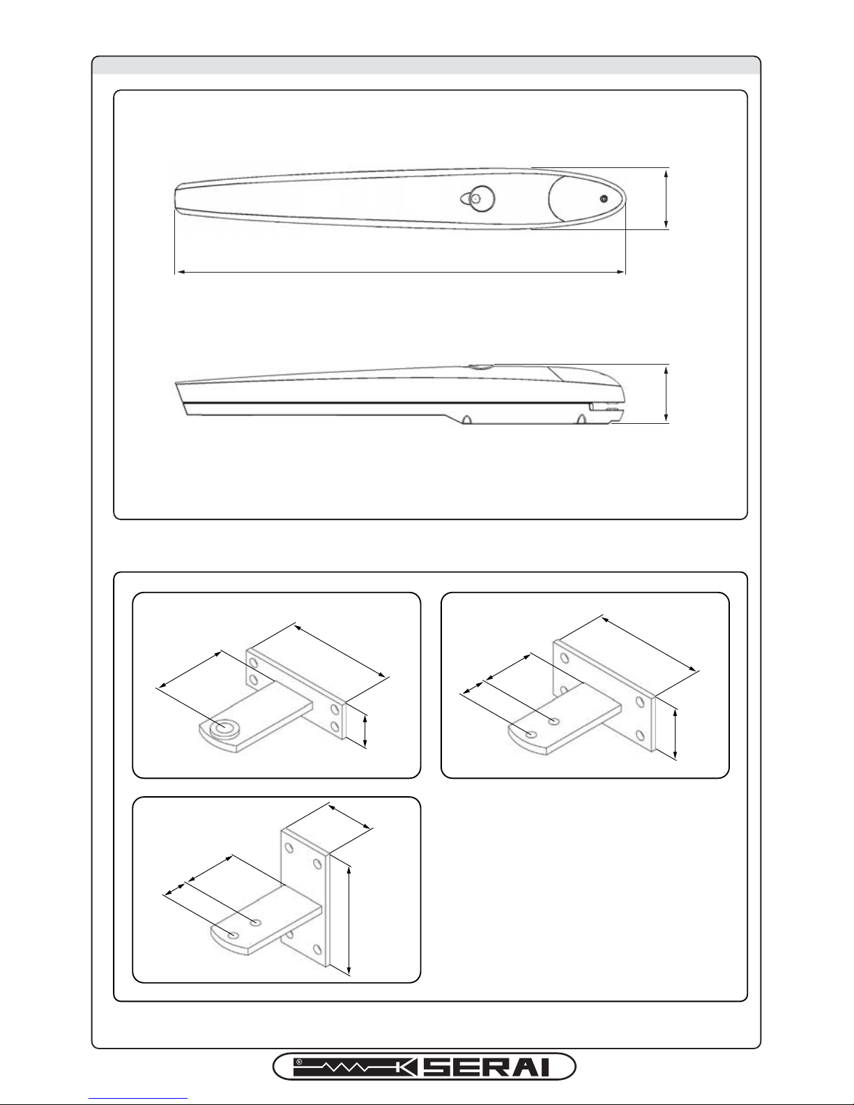
1C - OVERALL DIMENSIONS
780
104
100
130
40
130
130
80
80
Front
bracket
Rear bracket
horizontally soldered
Rear bracket
vertically soldered
120
20
120
20
95
Page 4
DAL 1965
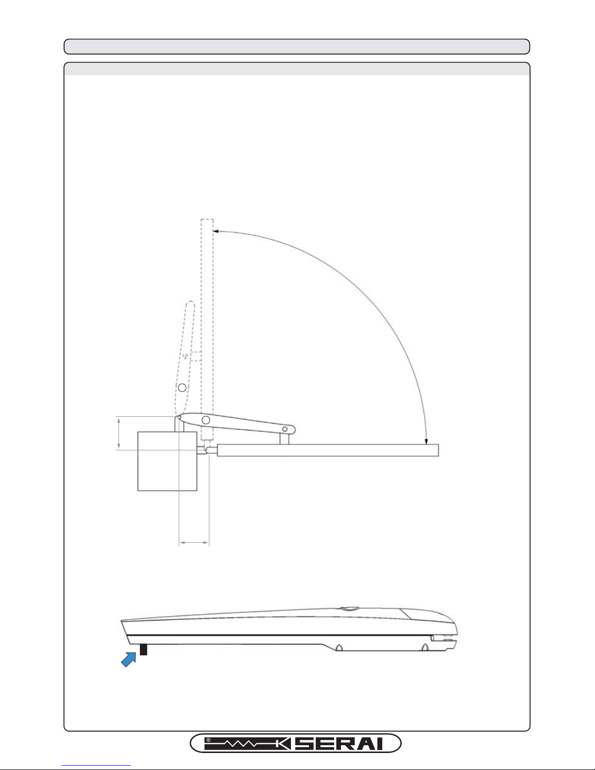
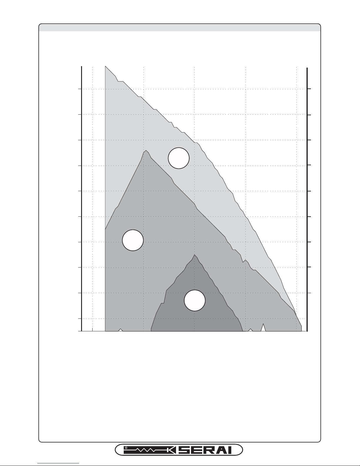
2A - HOW TO USE THE GRAPH
Measure "E", and draw a horizontal line on the graph at the read measure.
Choose a point on the
drawn line, considering the desired opening angle, suitable to the
column.
Draw a vertical line from that point and determinate the A value.
Verify that the A value allows the fixing of the rear bracket to continue the installation,
otherwise choose another point on the scheme.
Finally, bring the piston to the limit of the travel to fix the rear bracket to the leaf
(see the follo
wing picture).
This, however, by avoiding that the sliding pivot touches the aluminium body.
A
E
2 - BRACKETS INSTALLATION SCHEME
Page 5
DAL 1965
2B - GRAPH
If the installation measures are not properly followed, the atomation could not work
correctly.
For example:
- cyclical trends, and sudden accelerations,
- noise from the operator,
- limited opening degree or absent opening (if the operator was fixed counter-lever).
120 140 160 180 200
130
140
150
160
170
180
190
200
210
220
A (mm)
E (mm)
90°
100°
110°
Page 6
3 - INSTALLATION
3A - INTRODUCTION
Read the instructions manual accurately before installing the product. The producer disclaims all responsibility for any
damage or bad functioning caused by non-observance of the instructions or bad connection that may result in poor safety
and functioning of the operator.
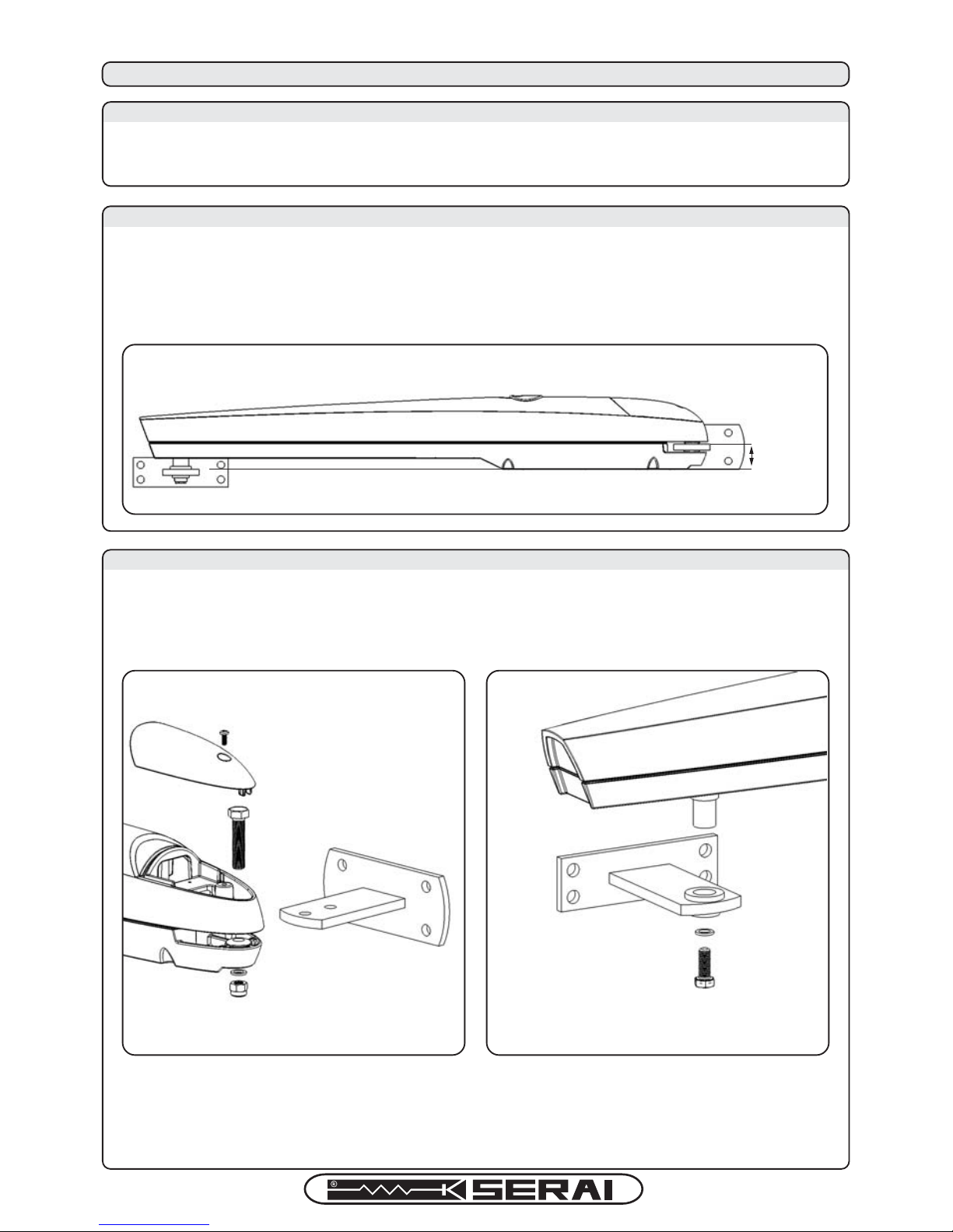
Fix the brackets allowing 35mm between the support planes in order to fix the operator with a perfect
horizontal alignment (see pic.1).
35mm
1
Fix the operator to the rear bracket (see pic.2).
Fix the operator to the front bracket (see pic.3).
23
DAL 1965
3B - BRACKETS HEIGHT
3C - FIXING THE OPERATOR TO THE BRACKETS
Page 7
4A - INTRODUCTION
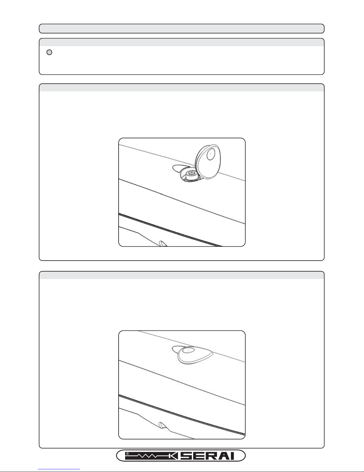
! Before operating the manual release disconnect the power.
Manual release of the gate was thought to open/close it manually in case of power loss or operator breakdown.
4B - MANUAL RELEASE
INSTRUCTIONS (see pic.4).
- Open the manual release cover.
- Insert the key in the cylinder and turn it 90° anticlockwise.
4 - OPERATING THE GATE MANUALLY
4
DAL 1965
4C - RESTORING THE AUTOMATION
INSTRUCTIONS (see pic.5).
- Insert the supplied key in the cylinder and turn it 90° clockwise.
- Close the manual release cover.
5
7
Page 8
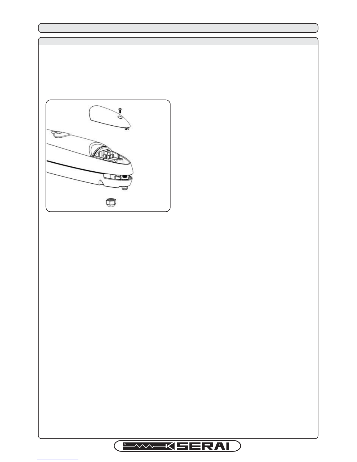
To connect the operator to the control unit proceed as follows:
01.
Remove the lid of the operator as shown in pic.6.
02.
Loosen the cable gland, pass the cable through it, screw its 3 wires to the terminal blocks, then tighten the gland.
03.
Replace the lid on the operator.
To check the connections, the direction of rotation of the operator, the delay between the movements of the 2 leafs and to
program the gate main positions, refer to the instructions manual of the control unit.
6
DAL 1965
8
5 - ELECTRICAL CONNECTIONS
5A - CONNECTING THE OPERATOR TO THE AUTOMATION CONTROL UNIT
Page 9
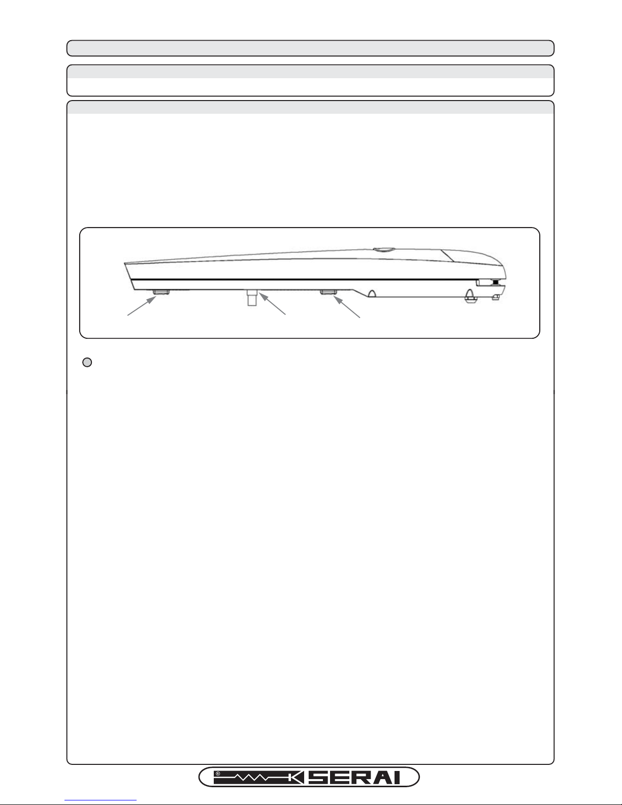
! Operators are supplied by fabric default with one internal mechanical stop, to set the opening position. If
the gate can't be provided with a closing external mechanical stop, an optional closing internal mechanical
stop (D) can be ordered separately (M/00, code 14.00).
6A - INTRODUCTION
An internal mechanical stop allows to stop the gate at a pre-set position, avoiding to hit the external leaf mechanical stop.
6B - ADJUSTMENT INSTRUCTIONS
INSTRUCTIONS (see pic.7):
- Release the operator for manual movement (see 4B).
- Loosen the screw of the supplied mechanical stop (B).
- Move the door to its wide open desired position.
- Place the mechanical stop next to the sliding pin (C), as a block.
- Firmly tighten the screw of the mechanical stop.
- Restore the operator automatic functioning (see 4C).
6 - MECHANICAL STOPS ADJUSTMENT
7
B
C
D
DAL 1965
Page 10
TIPO:
Type:
MODELLO:
Model:
Attuatore elettromeccanico per cancelli a battenti
Electromechanical gearmotor for swing gates
MT/BZERO
Risulta conforme a quanto previsto dalle seguenti direttive europee:
Satisfies the essential requirements of the following Directives:
DIRETTIVA BASSA TENSIONE
Low Voltage Directive
2006/95/CE
EN60335-1
EN60335-2-103
DIRETTIVA MACCHINE
Machinery Directive
2006/42/CE
COMPATIBILITÀ ELETTROMAGNETICA
Electromagnetic Compatibility
2004/108/EC, 92/31/EEC, 93/68/EEC, 91/263/EEC
EN61000-6-1
EN61000-6-3
Come previsto dalla direttiva 2006/42/CE si avverte che non è consentita la messa in
servizio del prodotto sopra indicato finché la macchina, in cui il
prodotto è incorporato, non sia stata identificata e dichiarata conforme alla direttiva
2006/42/CE.
As specified in the directive 2006/42/CE use of the product specified above is not admitted
until the machine on which it is mounted has been identified and declared as
conforming to the directive 2006/42/CE.
',5(C7,9(SANDSTANDARDS
DAL 1965
10
Page 11

NOTES
DAL 1965
11
Page 12
WARRANTYCONDITIONS
The companyreserves the rightto make anymodification without priornotice. The conventionalSERAI product warrantyis valid 24months following theissuance of thefiscal
document attesting to its purchase. Services covered by the warranty are provided at the company's facilities in Legnaro (PD - ITALY) or at any one of the company's
authorized ServiceCentres. The relativeshipping and transportcosts are at the Customer'sexpense. For TechnicalAssistance call: +39.049.790.858, Monday to Friday 8:30
to 12:30 and 14:00 to 18:00. The warranty shall be retained void in the event of any tampering with the product or in the event that the label specifying the product's production
batch has beenbroken or removed.
2011/65/UE DIRECTIVE ABOUT THE RESTRICTION OF THE USE OF CERTAIN HAZARDOUS SUBSTANCES IN ELECTRICAL AND
ELECTRONICEQUIPMENT (RoHS)- 2012/19/UE DIRECTIVEABOUT THE WASTEOF ELECTRICALAND ELECTRONIC EQUIPMENT(WEEE)
This device was manufactured according to the restrictions set by the RoHS directive. To protect the environment: when no longer needed, the device
must not bedisposed of as mixed municipalwaste. Takeit to anappropriate WEEE (Wasteof Electric and Electronic Equipment) waste collection facility.
CEDECLARATIONOF CONFORMITY
SERAI srl herebydeclares that the product MT/BZEROwas designed and manufactured in full compliance with the above mentioned directives and standards.
ELETTRONICA PADOVA
DAL 1965
www.serai.com
+39 049 79 08 58
+39 049 88 30 529
+39 049 79 02 95
MADE IN ITALY
VIA ENRICO FERMI, 22
35020 LEGNARO - PADOVA
ITALIA
STAMP
REGION:
PHONE:
CONTACT PERSON:
INSTALLATOR DATA
COMPANY:
LOCATION:
 Loading...