

Page 1
MT/x04 V01 P08 20140612
A4VL 40g/m
2
- IS MT/x04-E
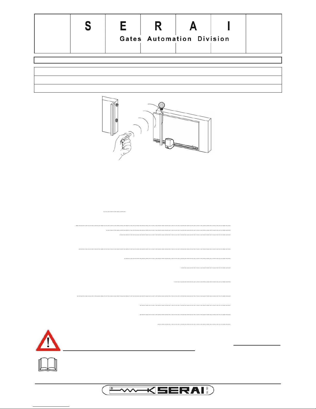
INSTALLATION MANUAL FOR 230Vac OPERATORS MERCURIO SERIES
MT/404
32.43
FOR THE AUTOMATION OF SLIDING GATES UP TO 400Kg
MT/604
32.63
FOR THE AUTOMATION OF SLIDING GATES UP TO 600Kg
MT/804
32.83
FOR THE AUTOMATION OF SLIDING GATES UP TO 800Kg
Thank you for choosing a SERAI ELETTRONICA product, which we are confident will perform to your requirements. Please be
advised that you are about to install a device part of a "system for the motorization of gates and doors in commercial or
residential buildings, accessed by vehicles", which must be considered potentially hazardous. By law you, as the Installer, are
obliged to take all the actions necessary to guarantee the safety of the users of the installation.
Installation and maintenance of this system must therefore be carried out exclusively by qualified, skilled and trained personnel,
following state-of-the-art rules, according to the law requirements. The law prohibits both the implementation of this type of
installations and their maintenance to unqualified personnel.
Product category and intended use: operator for the motorization of gates and doors up to 400-600-800Kg for vehicular
access, in commercial, residential and light industrial environments.
Reference Directives:
Low voltage (LVD):
2006/95/CE
Electromagnetic compatibility (EMC):
2004/108/CE
Restriction of hazardous substances (RoHS):
2011/65/UE
Generic reference standards:
Household and similar electrical appliances - safety - part 1:
generic standards:
EN60335-1: 2013
Electromagnetic compatibility - immuni ty - part 2:
generic standard for industrial environments:
EN61000-6-2: 2006
Electromagnetic compatibility - emission - part 3:
generic standard for commercial, residen tial and light industrial environments:
EN61000-6-3: 2007
Product-specific reference standards:
Household and similar electrical appliances - safety - part 2:
particular requirements for the motorization of gates, doors and windows:
EN60335-2-103: 2005
The installer is advised that the system he is going to i nstall, whose operator MT/ x04 is a component, will have to accomplish
also with the following directives and standards:
Machinery directive:
2006/42/CE
Industrial, commercial and garage doors and gates:
safety in use of power operated doors - requirements:
EN12453: 2002
Industrial, commercial and garage doors and gates:
safety in use of power operated doors - test methods:
EN12445: 2002
Industrial, commercial and garage doors and gates - product standard - part 1:
products without fire resistance or smoke control characteristics:
EN13241-1: 2011
ATTENTION!
SERAI products are designed to allow the realisation of installations in accordance with the aforementioned
standards. Compliance with these legal prescriptions is extremely important, because you, as the Installer,
are responsible of the installation and of its safe functioning.
IMPORTANT:
This manual must be read in its entirety before proceeding with the installation of the various
components of the system.
Page 2
2
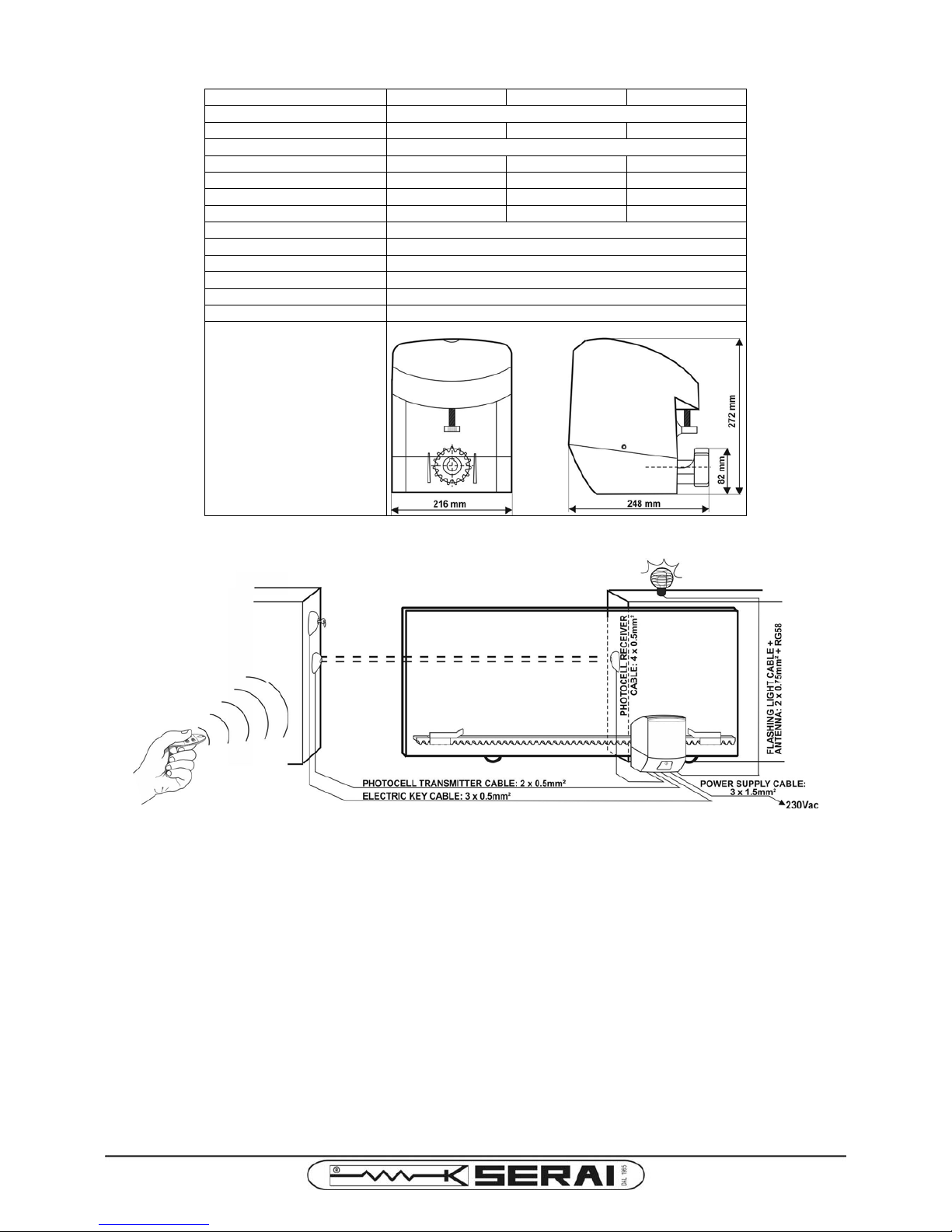
OPERATOR TECHNICAL DATA
MT/404 MT/604 MT/804
Operator characteristic irreversible
Leaf max. weight up to 400Kg up to 600Kg up to 800Kg
Operator supply voltage 230Vac ± 10% 50/60Hz
Capacitor 10µF 14µF 14µF
Max. absorbed current 2.1A 2.4A 2.8A
Absorbed power 245W 325W 335W
Starting thrust 350N 400N 490N
Operator strength regulated… …through operator supply voltage adjustment
Normal leaf speed 9.7m/min@50Hz - 11.6m/min@60Hz
Operator thermal protection 150°C
Reduction ratio 1:28
Protection degree IP44
Functioning temperature -20 ÷ +60°C
Dimensions 216 x 272 x 248mm
ELECTRIC WIRING EXAMPLE
RECCOMENDATIONS FOR A SAFE WIRING IN EXTERNAL GENERAL TYPE ENVIRONMENTS
1. Verify the presence of an isolating switch upstream the installation, with an open contact clearance of 3mm or higher.
2. Before operating any wiring, switch OFF the isolating switch (the "0" symbol should be visible). Verify that any source of
power is disconnected before wiring. Particularly, the control unit should never be powered during the wiring phase, nor
when connecting devices or expansions to it.
3. Wire the components of the system using the following types of cables:
- devices powered @230Vac (control unit, operator, flashing light): use cables having section 1.5mm
2
/ 2.5mm2 for length up
to 19m / 31m,
- devices SELV powered by the control unit (photocells, command buttons, electromechanical keys, etc.): use cables having
section 0.5mm
2
/ 0.75mm2 for length up to 50m / 100m.
4. Wire the earth connection in compliance with the standard prescriptions.
Page 3
3
INSTALLATION OF THE OPERATOR
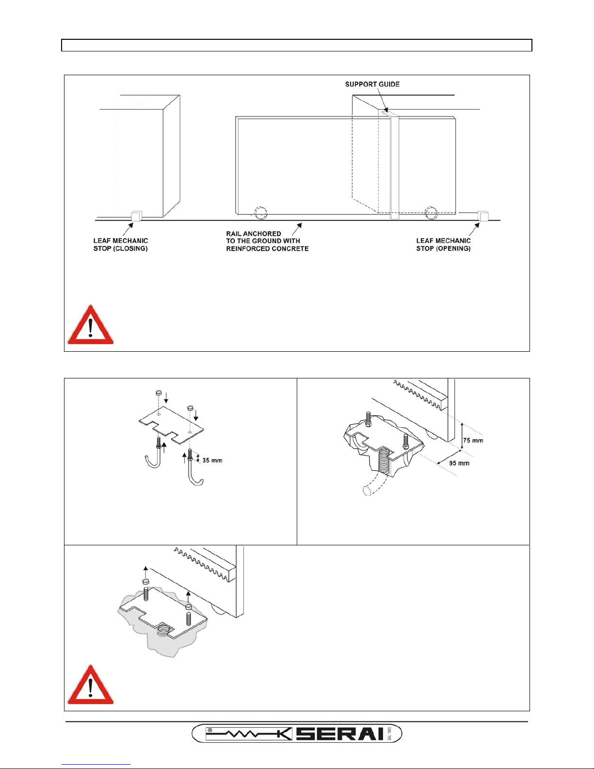
BEFORE STARTING
• Verify that the gate is equipped with a strong and solid support guide.
• Verify that the rail is securely anchored to the ground.
• Install 2 robust leaf mechanic stops and fix them strongly at the 2 ends of the rail.
• Verify that the leaf can move smoothly along the rail.
ATTENTION!
The installation of the mechanical opening and closing leaf stops is necessary to guarantee the
safety of the installation and of its users. The installation of the mechanical leaf stops is obligatory
before installing the operator.
INSTALLING THE BASE PLATE
A
• Screw one nut onto each of the 2 J-bolt, until it is
positioned 35mm from the end.
• Fit the J-bolts through the holes in the base plate.
• Screw another nut onto each J-bolt without tightening.
B
• Dig a hole, and place the base plate (fastened to the Jbolts) inside it, along with the cable carrier hose.
• Place the base plate respecting the specified positioning
quotes and fasten it keeping it in a flat position.
C
• Cast concrete to secure the unit to the ground, ensuring all
the base plate parts are kept clean, and the 2 nuts are
completely out of the concrete filling.
• Wait for the concrete to harden, then remove the 2 nuts.
ATTENTION!
If the installation location is subjected to flooding, the base plate must be placed high enough to
avoid the water reaching the operator.
Page 4
4
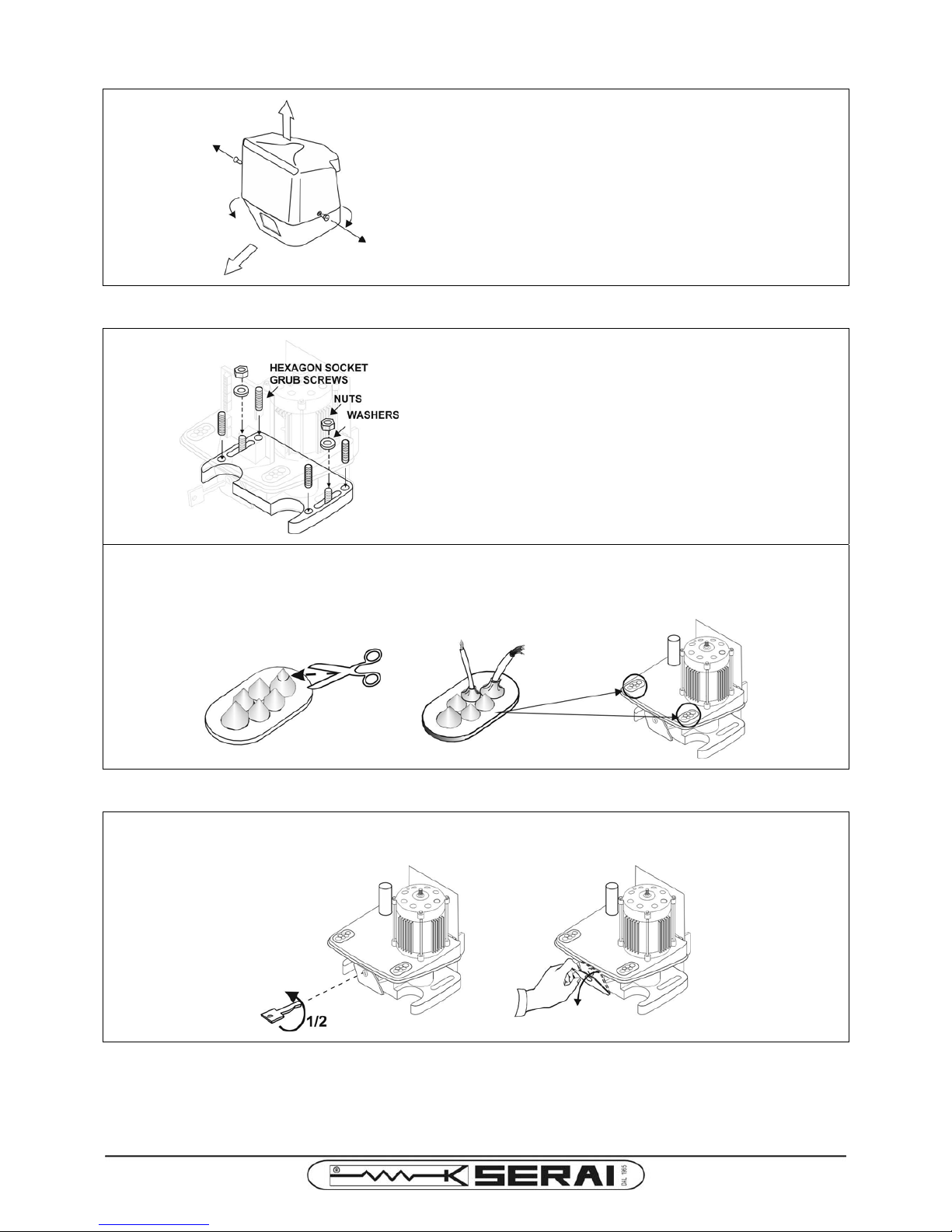
OPENING THE OPERATOR UNIT
• Remove the fastening screws at both the sides of the unit.
• Remove the operator plastic cover.
• Remove the operator plastic band from the lower part of
the unit.
POSITIONING THE OPERATOR
A
• Insert the 4 grub screws into their respective places and
screw them with an hex key.
• Position the operator on the base plate, inserting the
threaded parts of the J-bolts through the slots at both sides
of the operator base.
• Level the operator horizontally by regulating the grub
screws.
• Fit the washers onto the J-bolts, then screw the 2 nuts
without tightening them completely. These nuts will have to
be tightened only after the definitive placement of the tooth
rack.
B
• Bore small holes through the rubber seals, to grip adherently each cable passing through it. Otherwise, small insects
could penetrate into the operator and eventually reach the control unit causing short circuits that could
damage it irreversibly.
RELEASING THE OPERATOR MECHANISM
• Fit the release key into the lock in the front panel of the operator unit and give it half turn anti-clockwise.
• Push the release flap strongly downwards until the release mechanism is triggered.
Page 5
5
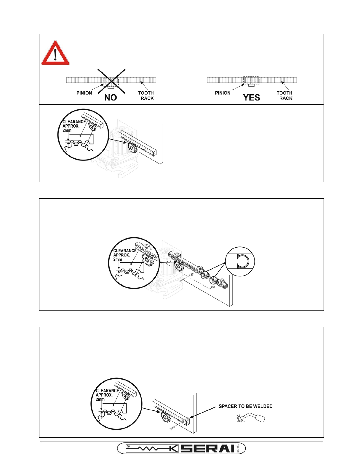
INSTALLATION OF THE TOOTH RACK
A
ATTENTION!
Regulate the operator horizontal positioning so that the pinion matches the tooth rack for the
entire width of the tooth.
B
• Place the tooth rack so that, moving manually the leaf all
along the rail, the distance between the pinion and the
tooth rack is constantly at ~2mm. A fine vertical adjustment
can be performed acting on the 4 grub screws (remember
to keep the motor base horizontal with respect to the
ground).
INSTALLATION EXAMPLE OF TOOTH RACK M/16 - UP TO 400Kg
Tooth rack in nylon PA66 charged with fiberglass. Fiberglass is used as reinforcement and increases the rack robustness.
• Juxtapose the tooth rack bars, each 340mm long, so that the complete "gate + operator + sliding plates" width is covered.
Fix the bars using self-tapping M6 screws, not supplied.
• Upon completion of the installation, vertically adjust the rack position through its slots, so that, moving manually the leaf all
along the rail, the distance between the pinion and the tooth rack is constantly at ~2mm.
INSTALLATION EXAMPLE OF STEEL TOOTH RACK M/14
• Juxtapose the tooth rack bars, each 1m long, so that the complete "gate + operator + sliding plates" width is covered,
eventually cutting the last bar to the right size.
• Weld the spacers supplied with the tooth rail to the leaf, and then apply the rail so that the spacers pass through the slots
on the rail itself.
• Fix the tooth rack to the spacers using the supplied bolts.
• Upon completion of the installation, vertically adjust the rack position through its slots, so that, moving manually the leaf all
along the rail, the distance between the pinion and the tooth rack is constantly at ~2mm.
Page 6
6
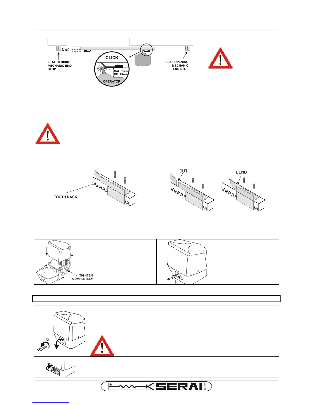
INSTALLATION OF THE END STOP SLIDING PLATES
A - POSITIONING
ATTENTION!
For safety reasons
install the leaf
mechanic end
stops for both
opening
and
closing
movements.
• Move manually the leaf along the rail up to 5cm from the closing position.
• Position the closing sliding plate over the tooth rack starting from the opening side of the leaf, and make it slide towards the
closing position until it operates the closing limit switch through the actuator spring: you'll hear a "click".
• Repeat for the opening position with the other sliding plate.
ATTENTION!
• To guarantee a correct limit switch operation, ensure a distance of 30mm (tolerance ±5mm)
between the rear side of the operator and the sliding plates. A distance greater than 35mm can
cause the leaf to block when reaching opening or closing positions. A distance smaller than
25mm can cause the actuator spring breakage.
• The sliding plates should be set taking into account inertia and temperature variations, so that
the leaf should never reach the mechanic end stops during opening and closing movements.
Otherwise THE RELEASE FLAP COULD GET BROKEN
while attempting to release the operator
mechanism. Because of seasonal temperature differences, it is advised to control the actual leaf
stop positions both is summer and in winter.
B - FASTENING
• Once found the correct position, fasten the closing sliding
plate to the tooth rack using 2 supplied M6 grub screws.
• Repeat for the opening sliding plate.
• If necessary, the sliding plate can be shortened cutting a
piece and then bending part of the remaining plate.
DEFINITIVE OPERATOR FASTENING
A
• Tighten the nuts on the Jbolts completely.
• Put the plastic band back in
place and then the operator
plastic cover. Fix it at the
sides with its 2 screws.
B
• Lock the operator by
manually closing the release
flap and taking off the
release key from the lock.
• Move manually the leaf for a few centimetres in any direction until the pinion locks.
IN CASE OF POWER SUPPLY LOSS: MANUAL RELEASE OF THE OPERATOR
A
• Fit the release key into the lock in the front panel of the operator unit and give it half turn anticlockwise.
• Push the release flap strongly downwards until the release mechanism is triggered.
• The leaf can now manually be moved freely.
ATTENTION!
The leaf should not stop against the mechanical end stops
,
otherwise the
release flap could break when applying the force necessary to move it.
B
• To relock the operator, close the release flap and taking off the release key from the lock.
• Move manually the leaf for a few centimetres in any direction until the pinion locks.
Page 7
7
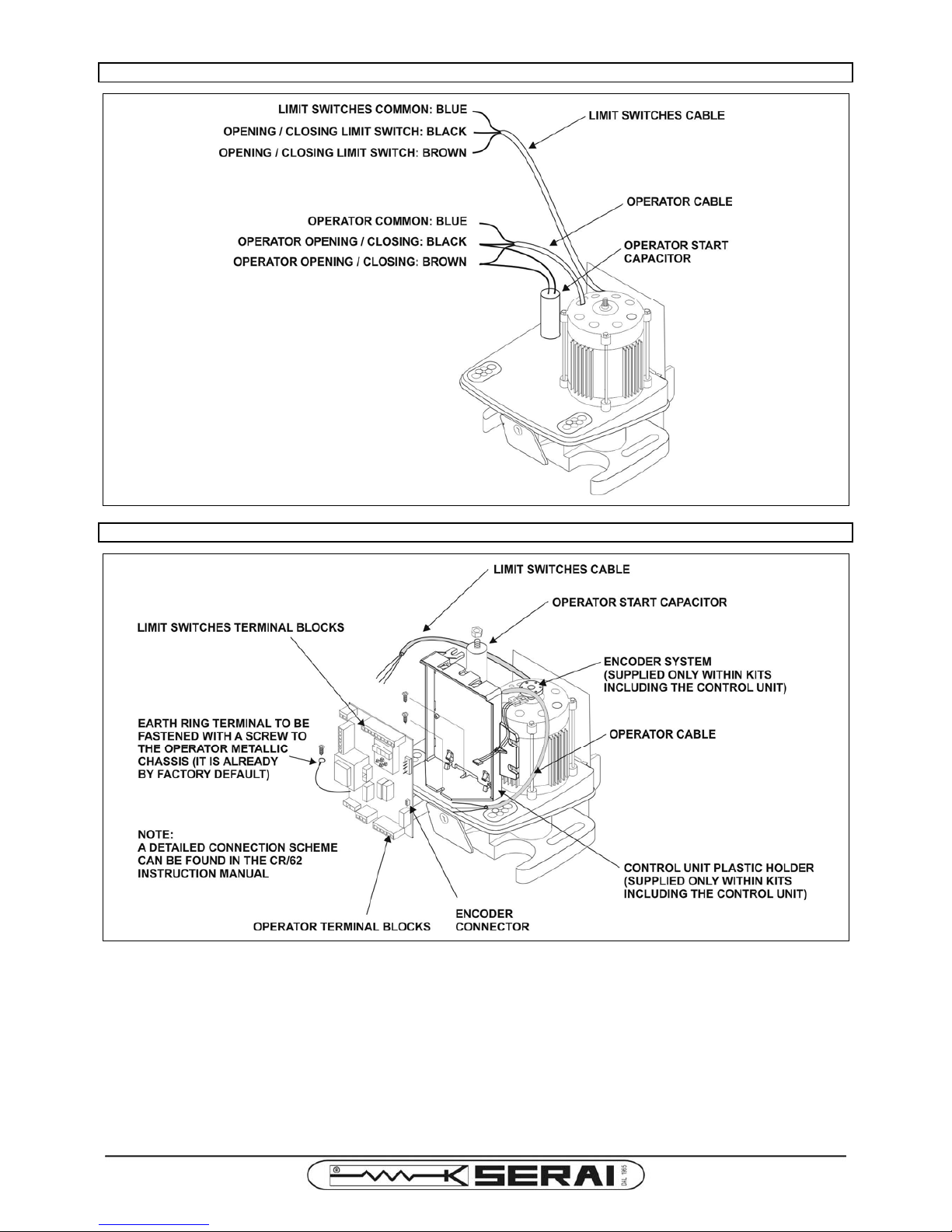
MT/404, MT/604, MT/804 CABLES DESCRIPTION
CONNECTING OPERATOR AND OTHER DEVICES TO THE STANDARD CR/62 CONTROL UNIT
Page 8
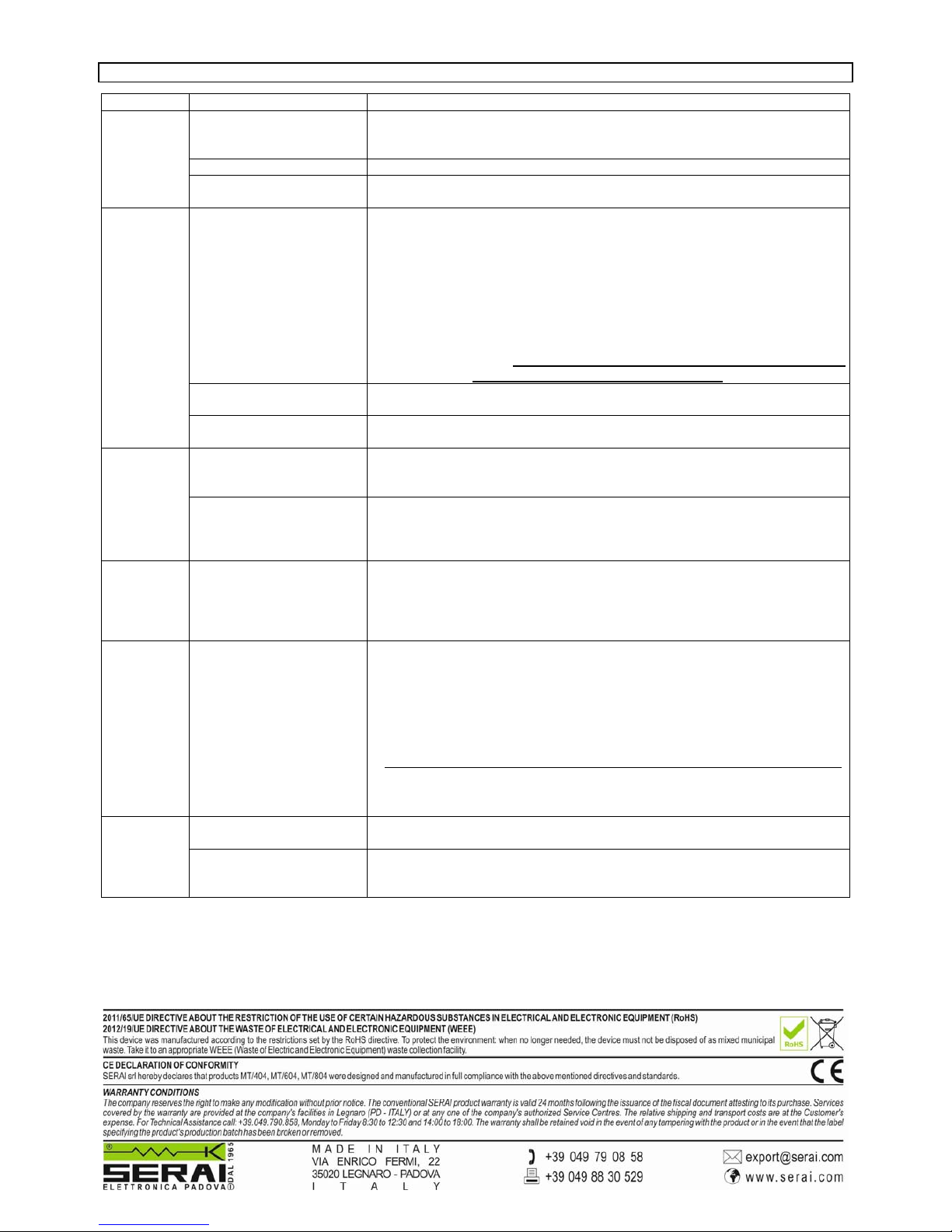
TROUBLESHOOTING GUIDE
PROBLEM CAUSE SOLUTION (to be applied only by qualified personnel, i.e. the Installer)
Power loss.
• Check the operator terminal blocks on the control unit for power supply
presence.
• Check the integrity of the operator supply cable and eventually replace it.
Fuse blown. • Replace the fuse.
The operator
doesn't work.
Thermal protection is active.
• Leave the operator stopped for at least 5 minutes; try a new manoeuvre when
it gets cooler.
With CR/62:
the impact control system
detected an obstacle.
• Switch the power off, manually unlock the release mechanism and eventually
remove any obstacle. Then relock the release mechanism.
• Repeat the leaf movement automatic learning procedure, or set more
appropriate values to parameters regulating operator strength and impact
sensitivity.
• Impact control can be set less sensitive or can be deactivated completely (see
CR/62 instruction manual). In this case other safety precautions must be taken
(for example a safety edge) in compliance with the laws in force.
ATTENTION!: Any modification must be taken by qualified personnel only,
since you, as the Installer, are responsible of the
installation and of its safe functioning.
Wrong end limit setting.
• Check and set the positions of the end stop sliding plates and their action on
the actuator spring.
The leaf
doesn't
complete its
travel.
Wrong operator positioning.
• Check the distance between the rear side of the operator and the sliding plates
to be between 25 and 35mm.
With CR/62:
decelerated manoeuvre after
a power loss.
• When the power returns, the leaf can be at half path. Next command will
cause a decelerated realignment to an end limit switch. Next manoeuvres will
be regular.
T
he leaf
moves slowly
even outside
the
deceleration
zones.
With CR/62:
decelerated manoeuvre after
an impact or after the
activation of the safety edge.
• Manoeuvres after an impact or after the safety edge intervention will be
performed as decelerated realignments to an end limit switch. Next
manoeuvres will be regular.
Starting a
manoeuvre,
the leaf
moves with
difficulty.
The operator start capacitor
is exhausted.
• Measure the capacitance of the capacitor and eventually replace it.
T
he leaf is
blocked
against the
mechanic
stop.
Sliding plates setting is
incorrect.
• Remove the operator plastic band from the lower part of the unit.
• Unscrew the nuts on the J-bolts completely and take off the washers.
• Slip off the operator from its position on the base plate to release the pinion
from the rack.
• Manually move the leaf far from the mechanic stop.
• Unlock the operator pushing down the release flap.
• Reposition the operator on the base plate.
• Reposition the sliding plates accurately (follow the given procedure).
• Put the plastic band back in place and lock the operator raising the release
flap.
• Repeat the leaf movement automatic learning procedure.
Unreliable connection of the
antenna.
Check the correct installation of the antenna cable at the terminal blocks of both
the control unit and the flashing light.
Radio
coverage of
remote
controls is
reduced.
External antenna needed.
To obtain the maximum radio coverage, disconnect the antenna inside the
flashing light and replace it with the optional external antenna OG/50 (SERAI
code 25.50).
 Loading...