

Page 1
MT/71 I E
DAL 1965
Pag. 1/5
MT/71 - SR 03.71 UNDERGROUND MOTOR FOR SWING GATE UP TO 2,20 +
2,20 METERS AND 250 kg PER LEAF - 24V
Thank you for choosing a SERAI ELETTRONICA product, which we are confident will perform to your requirements.
Please be advised that you are about to fit a system classified as “a power-operated drive designed to move automatic
gates and doors in commercial or residential buildings accessed by vehicles and persons”, and as such, the system
must be considered potentially hazardous. By law, you are responsible for rendering this equipment as “safe” as is reasonably possible.
Installation and maintenance of equipment of this kind must therefore be carried out by skilled, qualified and trained
personnel, working in a professional manner, as provided for by law n. 46/90 and any subsequent amendments and
supplements. The law in question prohibits the construction of these types of systems by non-qualified
personnel.
SERAI manufacturing complies with the following legislation:
Applicable directives for the CE marking :
Machines: 98/37/EEC
Low Voltage: 73/23/EEC
Electromagnetic Compatibility: 89/336/EEC
General applicable standards:
Electrical Safety: IEC EN60335-1 + IEC EN60335-2-103
Electromagnetic Compatibility - Emissions: CEI EN61000-6-3
Electromagnetic Compatibility - Immunity: CEI EN61000-6-1
Apart from the legislation mentioned above, you are also reminded to comply with the following standards during the
installation phase.
General applicable standards:
Safety of electrical systems in non-specialised environments: CEI 64-8
Specific product standards applicable:
Safety in the use of power-operated doors - requirements: UNI EN12453
Safety in the use of power-operated doors - testing methods: UNI EN12445
SERAI products enable users to build systems which comply with these standards. This is extremely
important as THE INSTALLER IS LIABLE FOR THE SYSTEM AND FOR ENSURING ITS OPERATION
COMPLIES WITH LEGAL PROVISIONS.
This handbook must be read in full before proceeding with the installation of the various parts of the system.
The installation of the mechanical end stops for gate opening and closure is necessary for system safety purposes and therefore this operation must be performed before proceeding with the installation of the control
unit.
!
E R A I
S
Gate Automation Division
INSTALLATION MANUAL
Page 2
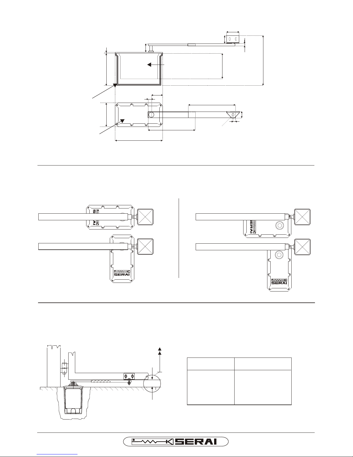
Fig. 1
MT/71 I E
DAL 1965
Pag. 2/5
OVERALL DIMENSIONS OF THE MOTOR
FOUNDATION
BOX
FOUNDATION
BOX + MOTOR
8 mm
202 mm154 mm
42 mm
20 mm
302 mm
70 mm
300 mm
MOTOR
300 mm
Ø16 mm
50 mm
170 mm
80 mm
15 mm
40 mm
15 mm
300 mm
BEFORE STARTING THE INSTALLATION
Check that the height from gate to the ground is more
Than 55mm. See Fig. 3.
----
---57 mm
56 mm
55 mm
Fig. 2
FOUR INSTALLATION POSSIBILITIES TO AVOID THE DANGER OF SHEARING
A - Motor installed completely under the gate B- Motor installed on side position
1st POSSIBILITY
Fig. 3
LENGHT AND WEIGHT OF THE GATE WING
In order to know the max weight that the gate can
have following the wing-lenght, please see the below
table:
ONE WING LENGHT ONE WING MAX WEIGHT
METRI 2,20 kg 250
METRI 2,00 kg 270
METRI 1,80 kg 300
METRI 1,60 kg 330
2nd POSSIBILITY
1st POSSIBILITY
2nd POSSIBILITY
Page 3
A
90
°
Fig. 5
90
°
A
B
!
A
mi
n
.
9
0
m
m
A
m
i
n
.
9
0
m
m
C
C
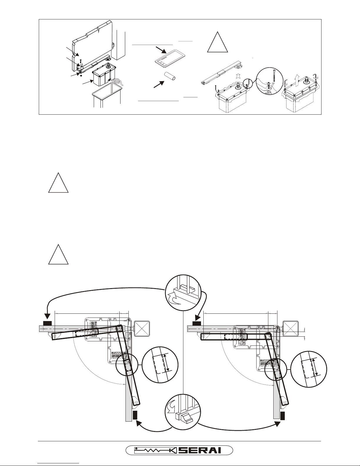
1- Install the gate stop blocks, choose the motor position and the opening angle refering to the following shares
see picture 5 :
- Share A: MAX 100mm. The motor could be installed near the pillar if there is a movable hinge, to allow the
motor insertion
- Share B: 30 ÷ 40 mm. In any case keep the parallelism among telescopic arm and the gate-wing.
- Share C: 330 ÷ 340 mm
- The installation of the mechanical end stops for gate opening and closing is necessary for
system safety purposes.
For a correct working and in order to avoid the shearing strictly respect the above mentioned
shares with a tolerance of +10 mm.
1.A- In the event that the suggested shares cannot be respected, or for openings exceeding 90°, you have to use
the long telescopic arm SR93.97 in accordance with the new shares:
- Share A: MAX 150mm
- Share B: MAX 100 mm
- Share C: 430 ÷ 440 mm
ATTENTION:
Using the long telescopic arm, shearing-danger conditions may happen.
ATTENTION:
-
!
DAL 1965
Pag. 3/5
TELESCOPIC
ARM
MOTOR
FIXING
BRACKETS
GATE
IMPORTANT:
FEEDER
Fig 4
LONG
SCREW
!
FOUNDATION BOX
FOR THE MOTOR
SPACING TUBE TO BE INSERETED
ON THE FOUNDATION BOX BEFORE
THE CEMENTING PHASE
SPACING SHEET TO BE INSERTED
ON THE FOUNDATION BOX BEFORE
THE CEMENTING PHASE
LONG
SCREW
ATTENTION:
FOR LIFTING THE MOTOR FROM THE
FOUNDATION BOX, TAKE OUT TWO
STANDARD SCREWS AND FIX TWO
LONG SCREWS IN THEIR PLACE.
Motor installed completely under the gate
Motor installed on side position
MT/71 I E
Page 4
!
Fig 6
Fig 11
Fig 12
!
MT/71 I E
DAL 1965
Pag. 4/5
Fig 7 Fig 8
Fig 9 Fig 10
300 mm
2
50 mm
4
00
m
m
CERNIERA
DEL
CANCELLO
TUBO
PASSAGGIO
CAVI DI ALIMENTAZIONE
GATE
HINGER
PIPING FOR
FEEDER PASSING
2-
6
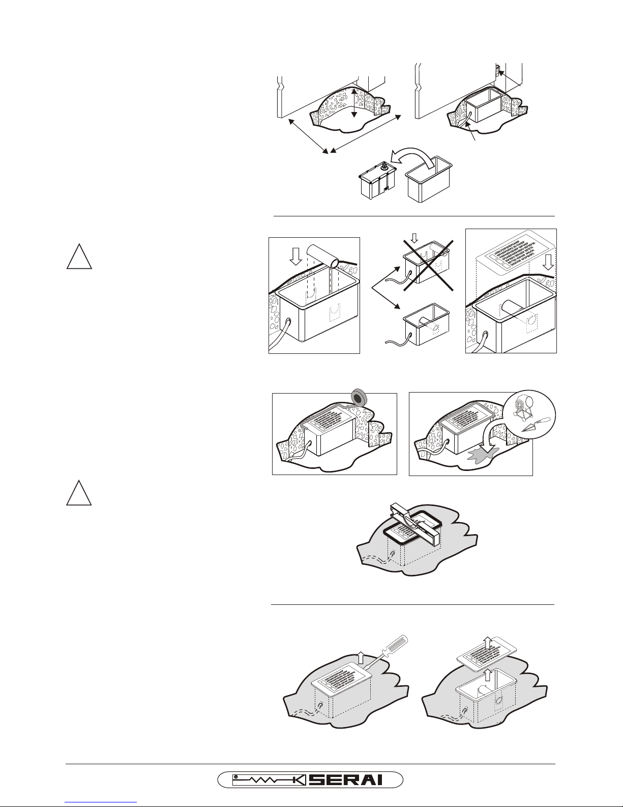
3- Prepare the piping and open the cable entries
on the foundation box for the electric
connections. See Fig. 6
4- Insert the spacing plastic tube on the
Foundation box. See Fig. 7
CAUTION:
ensure that the spacing tube is
centred both in horizontal and
vertical position with reference
to the foundation box.
5- Insert the spacing sheet on the Foundation
box. See Fig. 8
Prepare the excavation for the housing of the
foundation box. Remove the motor from the
foundation box, place the foundation box
ground level and verify the horizonal level and
the vertical alignment of the pivots. See Fig.
6- Seal up with adhesive tape. See Fig. 9
7-Cement definitively with concrete. See Fig. 10
ATTENTION:
During the cementing phase the
foundation box may rise up. Keep the
foundation box anchored. See fig 11
8- Before inserting the motoreducer take off the
spacing sheet and the plastic tube. See Fig. 12
NO
OK
Page 5
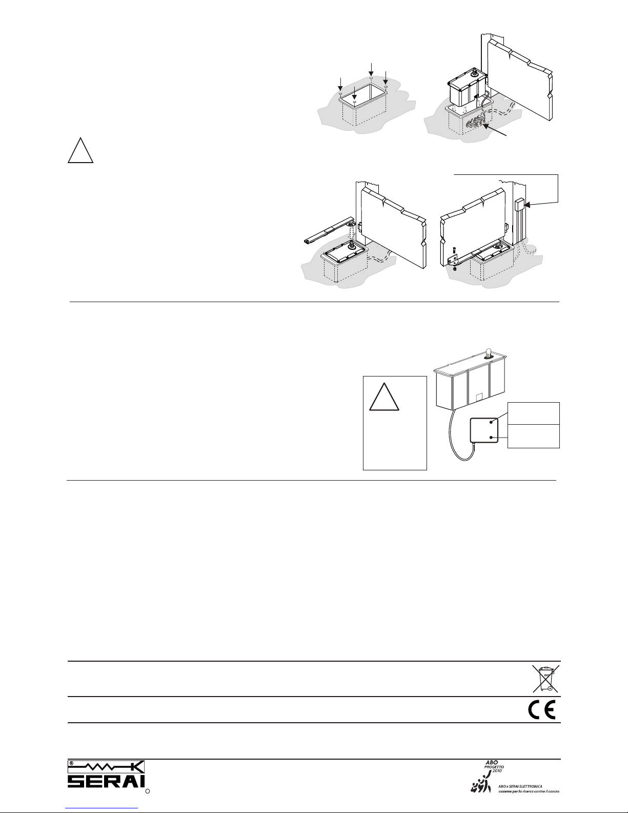
Fig 13
!
9- To make easy the eventual removal of the motor
and avoid any damage of the foundation box, insert
the 4 galvanized plates (which are supplied) in the
4 ends-inside the special circular places. See
picture no. 13.
10- Insert the motor, the telescopic arm and fix the
bracket on the gate. See Fig. 13.
IMPORTANT: lubricate the telescopic arm with
grease.
ATTENTION:
- Leave at least 35 cm of feeder under the
motor, for taking out the motor in case of
maintanance. Fig. 13
- The connection between the power supply
cable of the motor and the cable of the
control panel has to be carried out outside
the foundation box and inside a weather
proof housing. On the contrary a water
infiltration may be occur through the
power supply cable causing the motor
failure. See Fig. 13
11- Give power supply to the motor.
Weather proof
casing
35 cm of feeder
SKY BLUE =
OPEN/CLOSE
BROWN =
OPEN/CLOSE
ELECTRIC CONNECTIONS OF MOTOR
Connect the motors to the electronic control unit by means of cables
2
with a section of 2.5 mm .
SKY BLUE cable : Open/Close
BROWN cable: Open/Close
TURN OFF
POWER
SUPPLY
BEFORE
WIRING-UP
!
Reversing electromechanical motor for wing gates up to 2.20m each gate-wing and max. weight 250 kg.
Power supply..................................................24 V- ±25% Weight..............................................................10,7 kg
Max leaf lenght......................................................2,20 m Opening time for 90°.............................................13 s
Max leaf weight......................................................250 kg Protection rating...................................................IP67
Max opening angle.....................................................180° Operating temperature...........................-20° ¸ +60°C
Max absorption..........................................................2,8A Dimensions......................................302x154x202mm
Power.......................................................................60 W
Max thrust............................................................175 Nm
Angular speed...................................................0,12 rad/s
GEARMOTOR TECHNICAL SPECIFICATIONS
MT/71 I E 01 05 080417 - A4Vf/r - IS MT71-IS-E
ELETTRONICA PADOVA
I
SINCE 1965
MADE IN ITALY
VIA ENRICO FERMI, 22
35020 LEGNARO - PADOVA
I T A L I A
PHONE +39 049 79 08 58
FAX +39 049 88 30 529
E-MAIL [email protected]
WEB www.serai.com
TERMS OF GUARANTEE
The company reserves the right to make modifications to the equipment without prior notice thereof. SERAI products are covered by a standard guarantee with a term of 24 months.
Coverage starts on the date on which the tax document constituting proof of purchase is issued and guarantee services shall be provided on the company's premises at Legnaro - PD or at the Authorised Service Centres. Carriage costs shall be borne by the Customer.
CE CONFORMITY DECLARATION
SERAI spa declares that the product MT/71 has been desifned and manufactured according to the above mentioned directives and standards
WEEE DIRECTIVE 2002/96/EC
This appliance was manufactured after 13/08/2005. To protect the environment: when the equipment is no longer needed, take it to a special WEEE (Waste Electric and
Electronic Equipment) collection centre. Do not dispose of it with normal household waste.
N.B. For stopping the gate-wings it is necessary to
install the electric lock -see the relevant
instructions-
Max. Working cycle: - opening.................................20s
- pause with opened gate........22s
- closing...................................20s
- pause with closed gate..........32s
 Loading...