

Page 1
DAL 1965
Pag. 1/5
MT/2A+CF/2A I E
MT/2A - 03.2A UNDERGROUND MOTOR FOR WING GATES UP TO 3,00 m AND 250 Kg
EACH WING - 230Vac
CF/2A - 03.CF FOUNDATION BOX
E R A IS
GATE AUTOMATION DIVISION
INSTALLATION MANUAL
!
Thank you for choosing a SERAI ELETTRONICA product, which we are confident will perform to your requirements.
Please be advised that you are about to fit a system classified as “a power-operated drive designed to move automatic gates and doors in commercial or residential buildings accessed by vehicles and persons”, and as such, the system must be
considered potentially hazardous. By law, you are responsible for rendering this equipment as “safe” as is reasonably pos-
sible.
Installation and maintenance of equipment of this kind must therefore be carried out by skilled, qualified and trained
personnel, working in a professional manner, as provided for by law n. 46/90 and any subsequent amendments and
supplements. The law in question prohibits the construction of these types of systems by non-qualified personnel.
SERAI manufacturing complies with the following legislation:
Applicable directives for the CE marking :
Machines: 98/37/EEC
Low Voltage: 73/23/EEC
Electromagnetic Compatibility: 89/336/EEC
General applicable standards:
Electrical Safety: IEC EN60335-1 + IEC EN60335-2-103
Electromagnetic Compatibility - Emissions: CEI EN61000-6-3
Electromagnetic Compatibility - Immunity: CEI EN61000-6-
Apart from the legislation mentioned above, you are also reminded to comply with the following standards during the
installation phase.
General applicable standards:
Safety of electrical systems in non-specialised environments: CEI 64-8
Specific product standards applicable:
Safety in the use of power-operated doors - requirements: UNI EN12453
Safety in the use of power-operated doors - testing methods: UNI EN12445
SERAI products enable users to build systems which comply with these standards. This is extremely important as
THE INSTALLER IS LIABLE FOR THE SYSTEM AND FOR ENSURING ITS OPERATION COMPLIES WITH
LEGAL PROVISIONS.
This handbook must be read in full before proceeding with the installation of the various parts of the system.
The installation of the mechanical end stops for gate opening and closure is necessary for system safety purposes
and therefore this operation must be performed before proceeding with the installation of the control unit.
Page 2
DAL 1965
Pag. 2/5
1
230V~
3x1,5 mm²
4 x 0,5 mm²
2 x 0,5 mm²
4 x 0,5 mm²
4 x 1,5 mm²
4 x 1,5 mm²
2 x 0,5 mm²
3 x 0,5 mm²
RG58 + 2 X 0,75 mm²
1
2
4
55
6
3
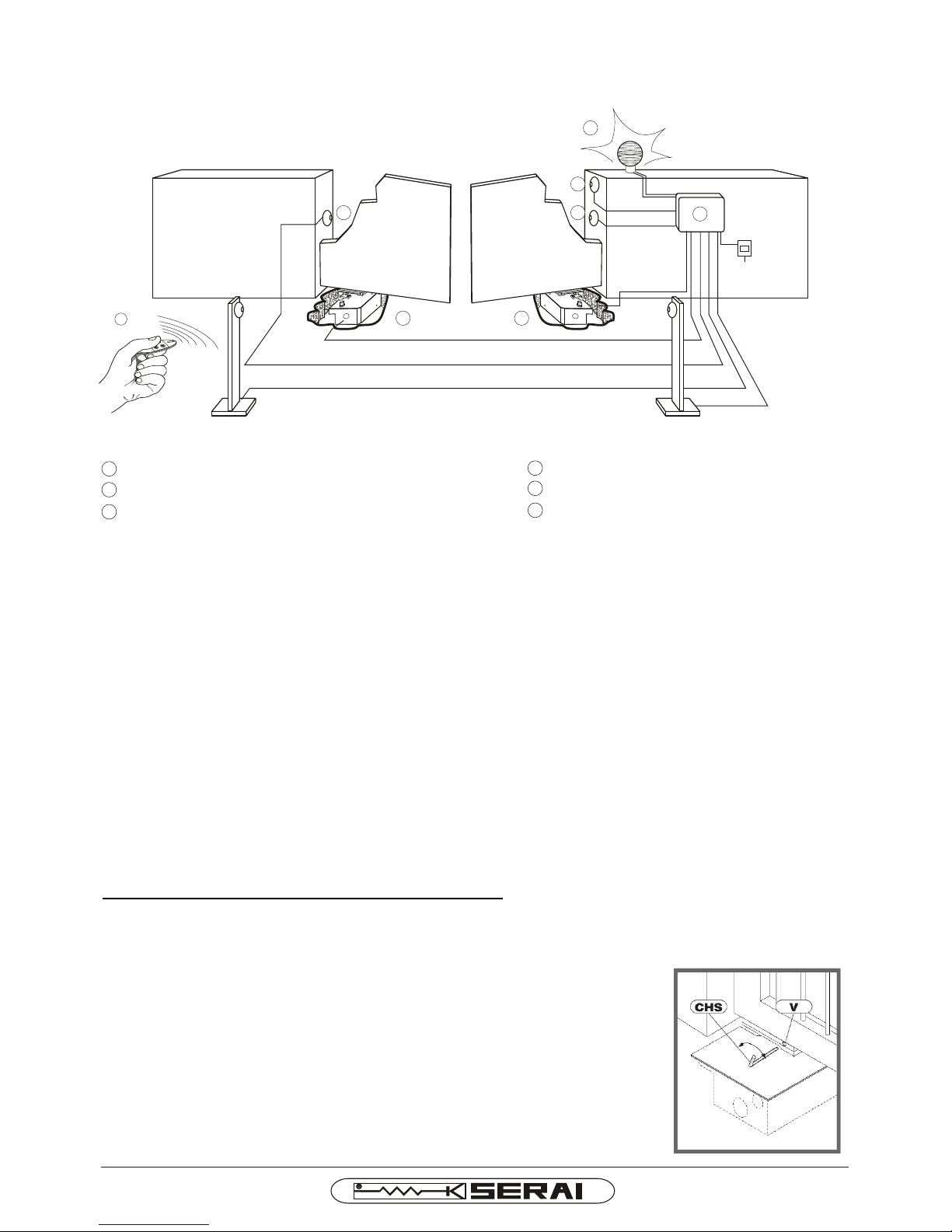
MT/2A I E+CF/2A
4 M/10 electric key
5 Pair of P/10 photocells
6 RZ/20 F Flashing light with antenna
1 MT/2A
2 CR/41 electronic control unit with built-in receiver
3 OG/62 2-channel minitransmitter
Geared motor
STANDARD INSTALLATION
Advice for wiring up in non-specialised environments.
1. Fit an omnipolar switch upstream of the system, choosing one with a gap of at least 3mm between the contacts. Or,
alternatively, use a 10A thermal magnetic circuit breaker.
2. Always make connections, of any type, with the system disconnected from the power supply, i.e. with the main switch
set to OFF (symbol “0”). The control unit, in particular, must never be connected to the power supply either during the
wiring up, or when fitting any expansion boards.
3. The following cables must be used for installation of the system:
22
- for the control unit, motor and electric lock power supplies: 1.5mm section for lengths of up to 19m, 2.5mm section
for lengths of up to 31m,
22
- for the flashing light: 0.75mm section for lengths of up to 3m, 1.5mm section for lengths of up to 19m,
- for the low voltage and current lines, (e.g. for the photocells, control buttons, electromechanical key, sensitive
22
edges and other safety devices: 0.5mm section for lengths of up to 50m, 0.75mm section for lengths of up to 100m.
4. Wire up the earth connection in compliance with legal provisions.
EMERGENCY OR MANUAL MANOEUVRE
You have to do the emergency or manual manoeuvre or during the installation, or only
if the automation does not work properly or if there is not power supply.
· Cut off the power supply.
· Put the supplied key “CHS” in the hole “V” and turn the left leaf clockwise or the
right leaf anticlockwise, to free the gear, so open the gate manually.
· In order to re-establish the normal functioning of the automation, you have to put
the leaf in the starting position (it starts automatically).
· Place the key “CHS” in a safety place known exclusively from the people intended
for the use of the automation.
· Switch on the power supply, pay attention that there's nobody where the gate is
moving.
Page 3
DAL 1965
Pag. 3/5
!
MT/2A I E+CF/2A
INSTALLATION
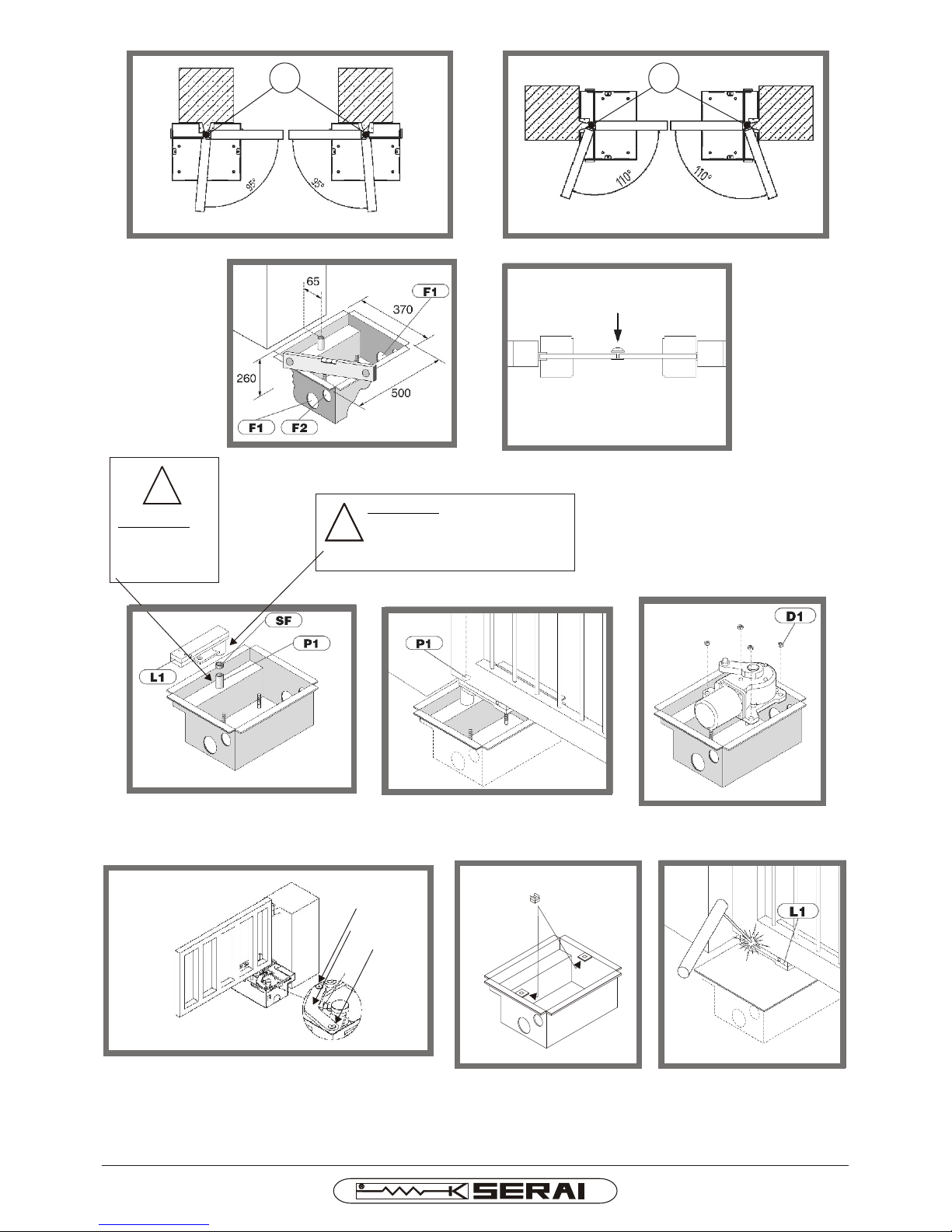
To operate a good installation of the gear motor MT/2A follow these instructions:
· Make sure that the leaves of the gate are perfectly horizontal
· Locate inside the property the correct point to install the gear motors remembering that: the pins “P1” which
comes out of the boxes must be always aligned with the rotation axis of the leaves (pivot) (fig. 1-2).
· Make sure that between the columns that support the gate and the pivots of the leaves there are like minimum
65 mm (fig. 3).
· We suggest to fix on the ground, in closing, a mechanical stop for the leaves (fig. 4).
· After deciding the right position, you have to make a digging on the ground to contain the metal boxes (fig. 3).
· Make sure that near the boxes holes “F1” there are a discharges for the water, to avoid a backwater that could
reduce the motor life (fig. 3).
· Foresee in the boxes holes “F2” the protective coverings for the power supply cables (fig. 3).
· Put inside of the boxes pins “P1” the spheres “Sf” so grease the pins “P1”, the spheres “Sf” and the holes of the
levers “L1” and after install the levers “L1” (fig. 5).
· Block the boxes in the holes with concrete and make sure that the boxes are perfectly horizontal, check that the
pins “P1” are aligned with the pivots and that the levers “L1” touch the lower border of the leaves (fig. 6).
· Put the gear motors on the bottom of the boxes and orient them like in the fig. 1-2, fix them to the tapping-
screws with the nuts “D1” (fig. 7).
· Install the transmission levers “L2” making coincide its holes with the pivots of the levers “L1” and “L3”, fix the
supplied safety screws. Adjust screws “V1” and verifying that the same touch the levers “L2” (fig. 8).
· Install the covers of the boxes checking if you forgot something's in the same.
· Align the levers “L1” with the leaves and fix them provisionally to the lower border by welding (fig. 10).
· Release the gear motors like in the paragraph “Emergency or manual manoeuvre” and carry out a manual
manoeuvre in opening and closing, to control the correct position of gear motors.
· Fix definitively the supports “L1” by strong and good welding.
WARNING:
- Never carry out circuitries inside the metal boxes.
- Make the electrical connections like in the control panel manual and install the obligatory safety
devices.
- Teach the people intended for the use of the automation about the controls, safety devices,
emergency manoeuvre and dangerousness deriving from the use of the automation.
·
To avoid dangerous situations that can cause accident or damages to things or persons, before starting the
opening or closing manoeuvres of the leaves make sure that the covers are installed and that anyone is
nearby the mechanism in movement and that anything's, as tools or cable, is inside the boxes.
Never carry out any adjustment operations without box cover or with the gear in working, before to operate
into the boxes make sure that the gear motors operations is finished and that the power supply is
disconnected.
Page 4
DAL 1965
Pag. 4/5
MT/2A I E+CF/2A
!
IMPORTANT:
GREASE THE
BOLT BEFORE
FITTING THE
LEVER GROUP
IMPORTANT:
USE THE PROPER GREASER TO
LUBRICATE PERIODICALLY THE
BOLT -EVERY 6 MONTHS
01
02
P1 P1
03
06
05
04
!
!
07
08
10
x2
09
L2
L1
L3
V1
Page 5
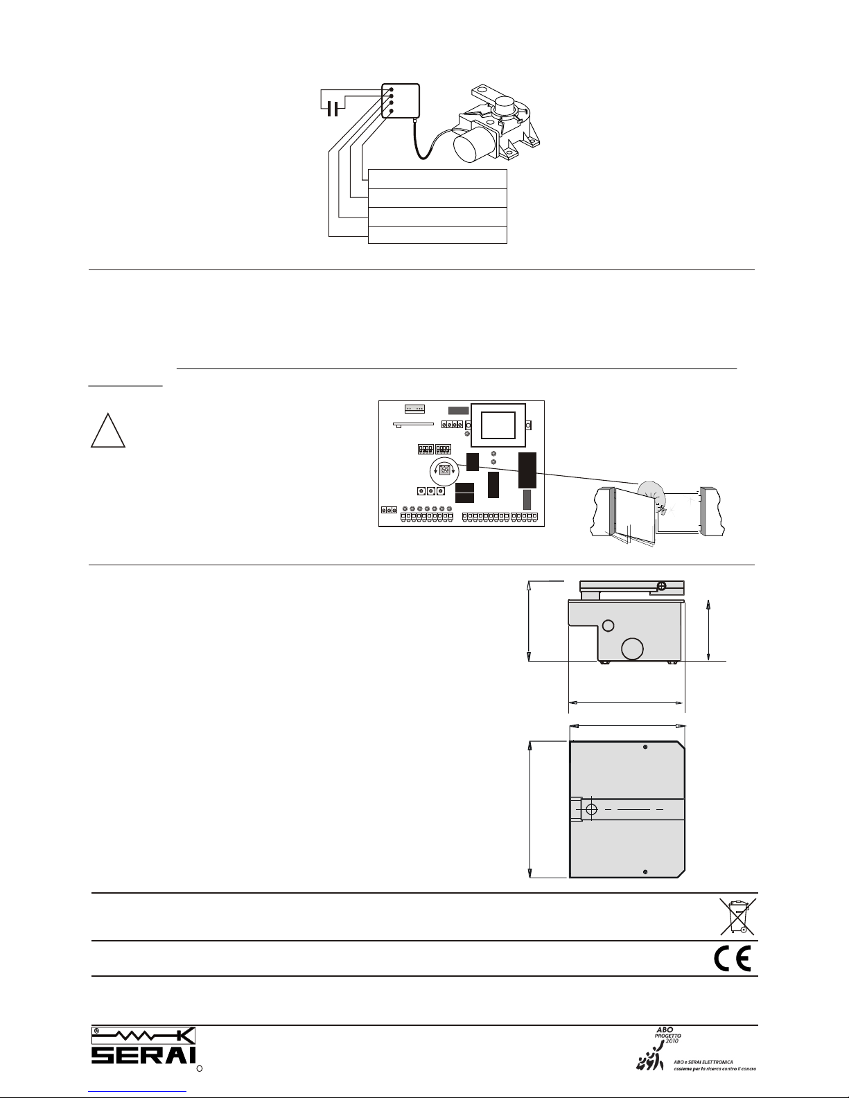
ELECTRIC CONNECTIONS
!
TECHNICAL SPECIFICATIONS
Power supply
Max. absorption
Max. leaf length
Max. opening angle
Max. leaf weight
Motor force adjusted via power supply voltage control
Protection rating
Motor thermal protection
Weight
.............................230 V~ ±10% 50/60 Hz
.........................1,2 A
Power ......................................190 W
max torque ................................375 Nm
Opening time .............................18 sec / 90°
.........................3,0 m
...................110°
........................250 Kg
:.................
Operating temperature .............-20° +60°C
........................IP66
............150 °C
- .....................................10 Kg
MT/2A I E 03 05 090512 -A4Vf/r -IS MT/2A-IS-E+CF/2A
380 mm
230 mm230 mm
320 mm
320 mm
170 mm
16 µF
450V
YELLOW GREEN = EARTH
GREY = COMMON
BLACK = OPEN/CLOSE
BROWN = OPEN/CLOSE
WARNING: the considerable
differences in temperature
between summer and winter can
cause differing rates of expansion
in all materials, including those
used in the building of our
motors. That is why we
recommend you check the impact
force setting at the start of winter
and summer.
MOTOR FORCE ADJUSTMENT
The motor force is adjusted by varying the power supply voltage via the “Power” potentiometer on the SERAI
CR/41 control unit.
In any event, installation must be in full observance with current standards governing power-operated gates;
remember that the installer is responsible for the system and operation in compliance with
standards.
ELETTRONICA PADOVA
I
SINCE 1965
MADE IN ITALY
VIA ENRICO FERMI, 22
35020 LEGNARO - PADOVA
I T A L I A
PHONE +39 049 79 08 58
FAX +39 049 88 30 529
E-MAIL [email protected]
WEB www.serai.com
TERMS OF GUARANTEE
The company reserves the right to make modifications to the equipment without prior notice thereof. SERAI products are covered by a standard guarantee with a term of 24 months.
Coverage starts on the date on which the tax document constituting proof of purchase is issued and guarantee services shall be provided on the company's premises at Legnaro - PD or at the Authorised Service Centres. Carriage costs shall be borne by the Customer.
CE CONFORMITY DECLARATION
SERAI spa declares that the product MT/2A has been desifned and manufactured according to the above mentioned directives and standards
WEEE DIRECTIVE 2002/96/EC
This appliance was manufactured after 13/08/2005. To protect the environment: when the equipment is no longer needed, take it to a special WEEE (Waste Electric and
Electronic Equipment) collection centre. Do not dispose of it with normal household waste.
F1F1
F2F2
ON
SW1
SW2
345 6
7
8
SOG/4
POWER
+
-
ON
PED START STOP FOTO FOTO AP FINE CH FINE AP
DL9
DL8
DL10
1 2
9
10 11121314 151617 1819 20 21 22
272526
2324
SET BREAK WORK
A B C
Com
+24
spia
RX
2829
 Loading...