

Page 1
KIT/45 84.45 CONTROL KIT OF ONE 24 VDC PARKING SPACE SAVER MOTOR
DAL 1965
Pag. 1/7
KIT/45 I E
Thank you for having chosen SERAI ELETTRONICA, certain that you will obtain the performance necessary for use
from this product.
Remember that you are about to install a system classified as "motorised activation destined to move gates and
automatic doors in commercial and residential buildings, with access of vehicles and persons", which is considered
as potentially dangerous. Normally, it is your task and responsibility to make this system "safe" for how much this is
reasonably possible
Installation and maintenance of such a system must therefore by carried out exclusively by trained, qualified and
expert staff, with "state-of-the-art" executions, as prescribed by DM 37/08 and subsequent amendments and
integrations. The law prohibits the realisation of these types of plants by unqualified staff
On realisation of its own products, SERAI has respected the following:
Reference Directives for CE marking:
machinery: 2006/42/EEC
low voltage: 2006/95/EEC
electromagnetic compatibility: 2004/108/EEC
General reference Standards:
electrical safety: IEC EN60335-1 + IEC EN60335-2-103
electromagnetic compatibility - emissions: IEC EN61000-6-3
electromagnetic compatibility - immunity: IEC EN61000-6-1
When installing the system, as well as that mentioned previously, please respect the following.
General reference Standards:
safety of electrical plants in general environments: IEC 64-8 V2
The SERAI products allow to implement systems that comply with these Standards. The following is very
important as THE INSTALLER IS RESPONSIBLE FOR THE SYSTEM AND ITS FUNCTIONING IN
COMPLIANCE WITH STANDARDS.
This manual must be read completely before proceeding with installation of the various parts of the plant
.
.
.
!
INSTALLER MANUAL
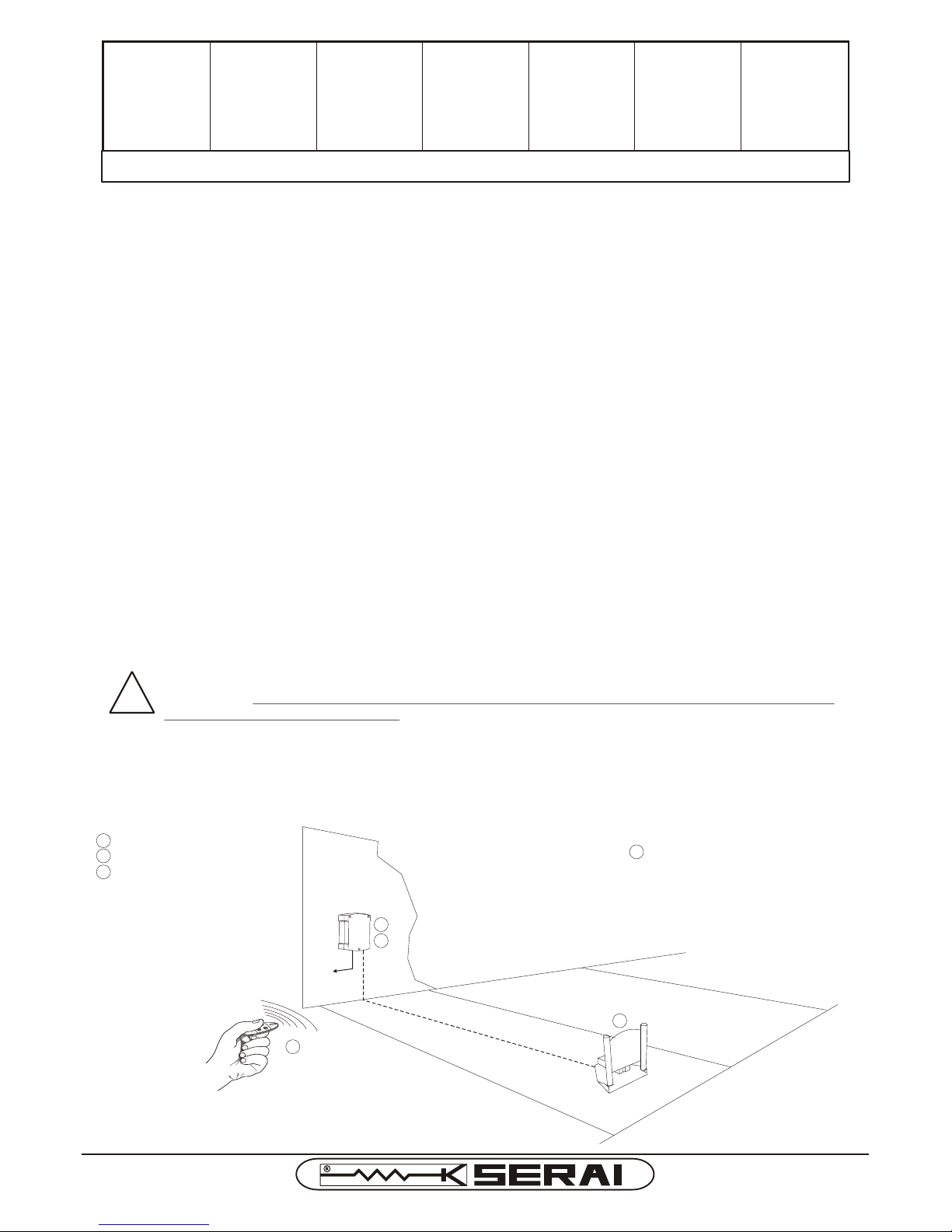
TYPICAL PLANT EXAMPLE
KIT COMPONENTS:
MP/30 motor
CR/53 control unit
OG/64 remote control
M I OM I O
P A R KP A R K
1
2
3
1
2
4
3
ACCESSORIES
2xBT/20: 12V 2Ah batteries
-optionals-
4
E R A IS
GATE OPENER DIVISION
Page 2
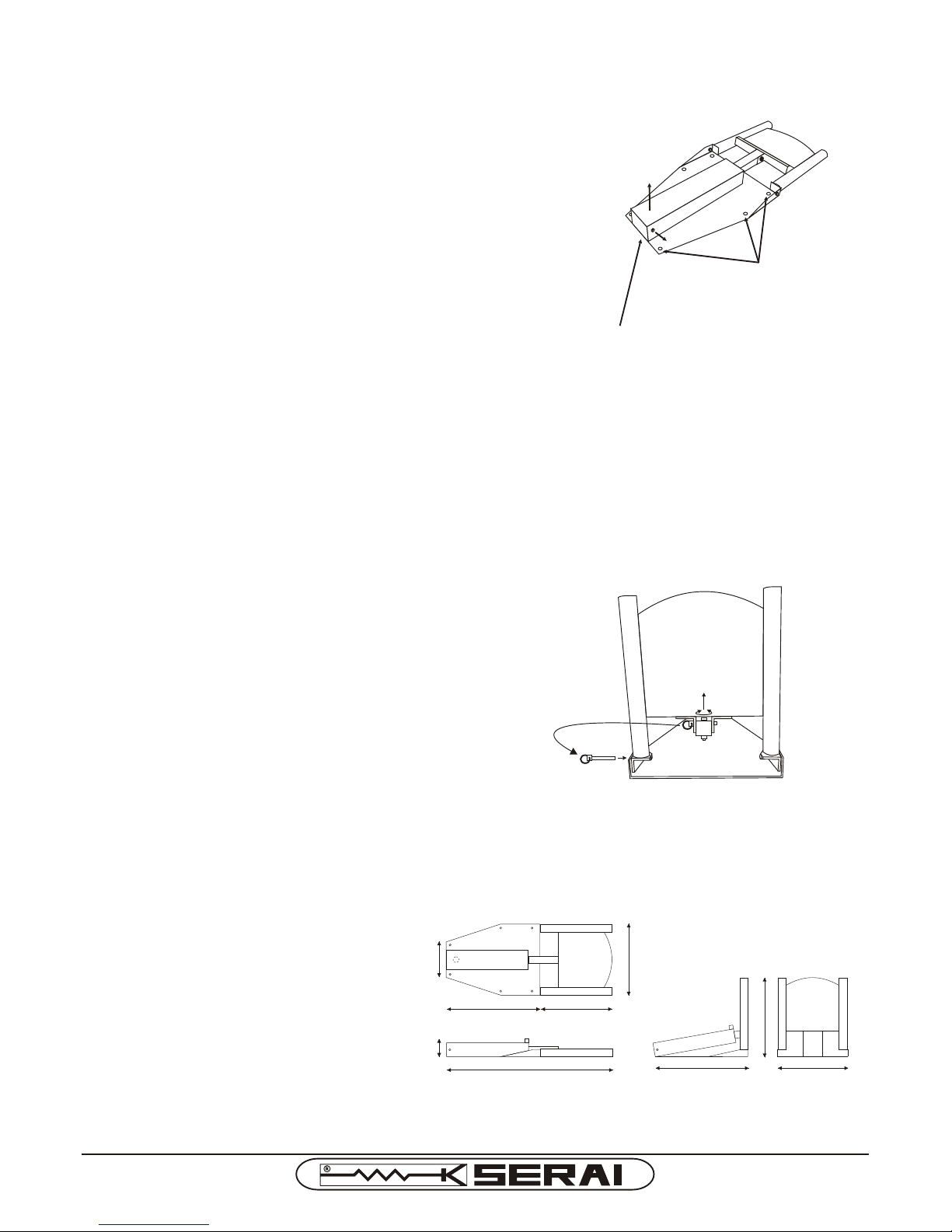
Find the installation position keeping in mind that the parking space
saver must remain below the car when parked.
If needed, make an adequate cement foundation to position the
parking space saver motor and arrange the arrival of the Ø=20mm
tube to pass the cables through the hole below the motor.
Using the base as a template, prepare 6 fixing holes using M8 screws
with dowels and fix the motor temporarily.
Remove the rear screw -A- and lift the casing -B- to access the
terminal board with the following connections:
red-black: 24Vdc motor
white-white: closing limit switch contact
Connect the power cables passing them through the underground
tube by means of the prepared inlet, below the motor, on the fixing
base.
Put the casing back in place and after connection to the control unit
make sure it works properly.
A
B
MANUAL RELEASE
MOTOR INSTALLATION
Unscrew the specific safety screw with a hex key from above or
by hand from below.
Remove the shear pin making sure the motor does not fall.
The motor is now released from the "gate" which can be moved
manually.
The pin can be used to position the gate back in the closed
position, inserting it into its side seat.
3 FIXING HOLES
ON EACH SIDE
CABLE INLET HOLE
BELOW MOTOR
TECHNICAL DATA OF MP/30 MOTOR
Power supply: 24Vdc ± 25%
Power and rated current: 24W - 1A
Moving time: 10s
Operating temperature: -20°C ÷ +60°C
Weight: 14Kg
M I OM I O
P A R KP A R K
M I OM I O
P A R KP A R K
840
475 365
Hmax=90mm
180
360
475 360
420
DAL 1965
Pag. 2/7
KIT/45 I E
Page 3
INSTALLATION OF THE CR/53 CONTROL UNIT
Position the appliance in proximity of the parking space saver in a way to reduce the length of the connection cable,
to the rest of the system, to a minimum.
For greater protection from atmospheric agents it is recommended to position the control unit under a roof or, even
better, in a room that has two lateral walls. It is also good practice to install the appliance higher than 1.5 m where
possible in order to prevent it being tampered with by children.
WHERE TO POSITION THE CONTROL UNIT
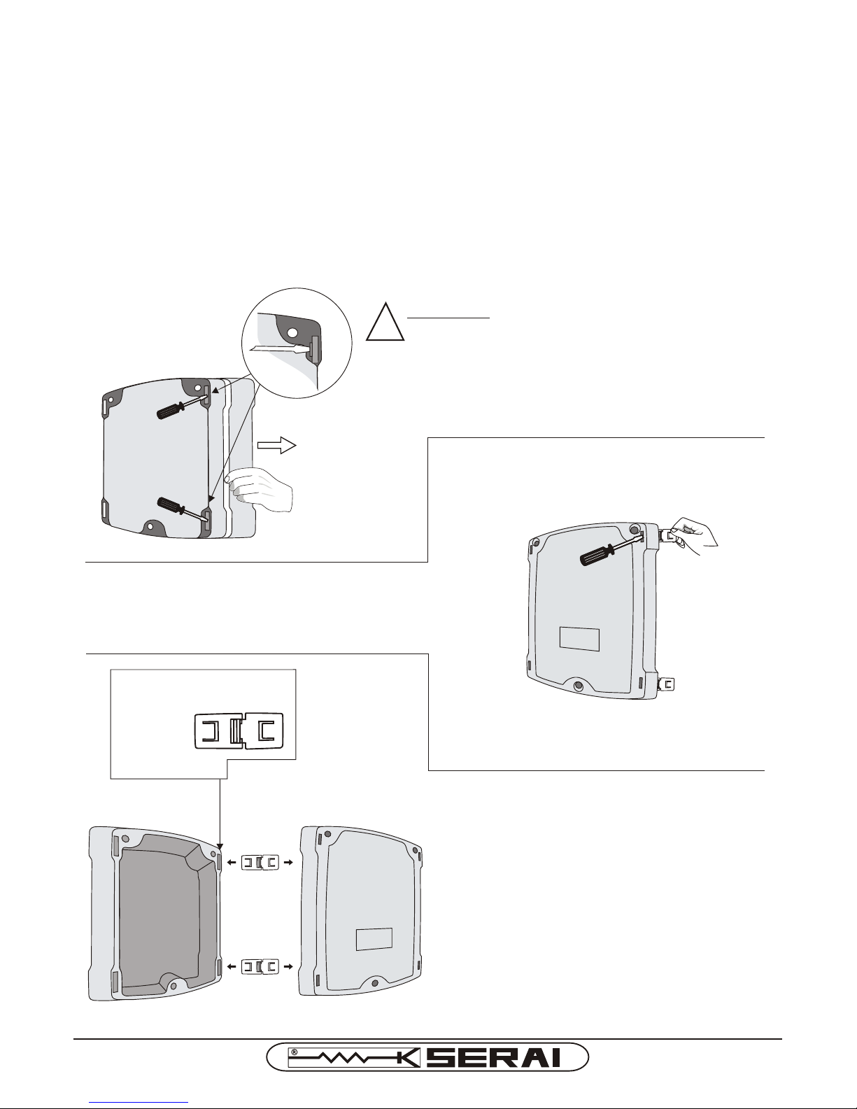
The control unit leaves the factory with the lid positioned to open from the left side.
If you wish to open the lid from the opposite side, proceed as follows:
ATTENTION: This operation must be carried out
before fixing the container to the wall.
Insert a flat tip screwdriver into the fixing recess of the hinges
positioned on the rear of the base and lever on the attachment
notch of the hinge itself, pulling the cover at the same time.
(see Fig.1)
Fig.1
Insert a flat tip screwdriver into the fixing recess of the hinge
positioned on the front part of the cover and lever on the
notched attachment of the hinge itself, pulling the hinge at the
same time. (see Fig.2)
Fig.2
Re-mount the hinges on the right side of the base by
inserting them in the relevant seats with the attachment
notch facing towards the inside of the container until the
attachment clicks (see Fig.3).
Fig.3
LID SET-UP FOR LID OPENING TO THE RIGHT
!
DAL 1965
Pag. 3/7
KIT/45 I E
Page 4
BATTERY HOUSING AND CABLES INLET
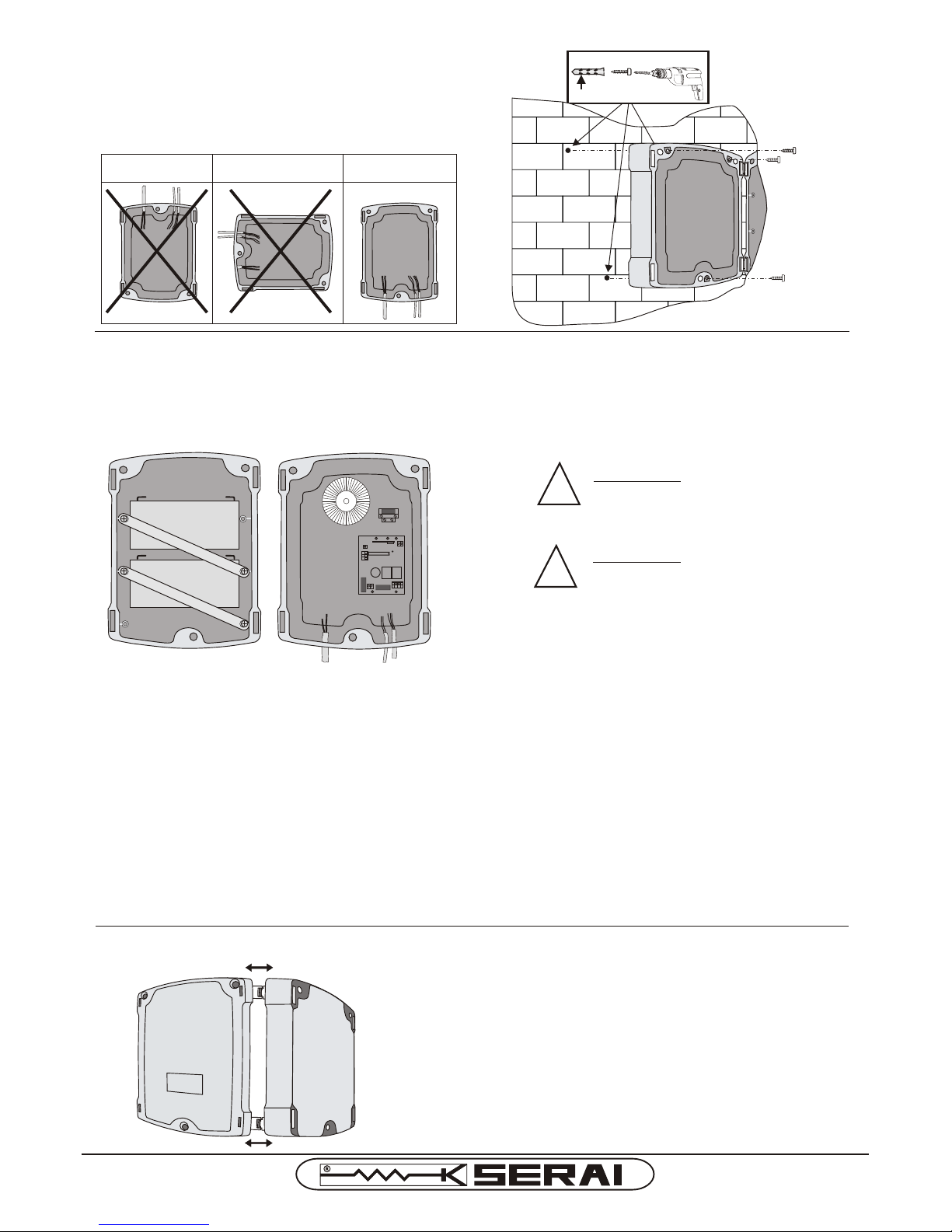
Seats for fairleads PG11 and PG 13,5 which are easy to break through, are envisioned in the lower part of the container
for the passage of input cables.
!
ATTENTION: Close all inlets well to
prevent the entry of insects, which
may damage the control unit.
Two strips are supplied complete with screws for fixing the two 12V 2 Ah batteries (SERAI BT/20) onto the lid of the
container.
!
ATTENTION: Considering the weight
of the batteries, it is recommended
to install them at the end of
mounting, before closing the box.
OPENING AND CLOSING THE BOX
When opening the box, make sure that most of the hinges
escape from the guide on the bottom of the control unit in order
to guarantee that the cover remains open without obstructing
the control unit wiring operations.
In the closing phase, accompany the cover “especially in the
presence of the battery” until complete return of the hinges. Pay
attention that the gasket is inserted correctly. Close the cover
using the appropriate screws.
FIXING THE CONTROL UNIT TO THE WALL
It is recommended to position the appliance in proximity
of the parking space saver in a way to reduce the length
of the connection cable, to the rest of the system, to a
minimum. The control unit must be fixed via the cable
passage holes facing downwards.
NO NO YES
Ø 6 ÷ 8 mm
Recommendations for connections in general environments according to the Italian Standard (IEC 64-8)
Upstream from the system, prepare an omnipolar isolating switch with distance of 3 mm or more between the
contacts. As an alternative, use a 10A magnet circuit breaker switch.
2. Make any type of connections always with the system not powered, i.e. with the isolating switch in the "open" position
("0" symbol). In particular, the control unit must never be powered during wiring or while any expansion cards are
being inserted.
.
1.
3. When installing the plant, use the following cables:
- for the power supplies to the motors: minimum 1.5 mm2.
- for the power supplies of the battery: minimum 2.5 mm2.
- for the power supplies of the control unit: 1.5mm2 cross-section for maximum length of 19m, 2.5mm2 cross-
section for lengths up to 31m.
- for low-voltage and current lines, such as control buttons: 0.5mm2 cross-section for maximum length of 50m,
0.75mm2 cross-section for lengths up to 100m.
1011
1 2
3 4 5 6
7 8 9
F2F2
F1F1
+ -
BATTERY
P1
DL1
F3F3
DAL 1965
Pag. 4/7
KIT/45 I E
Page 5
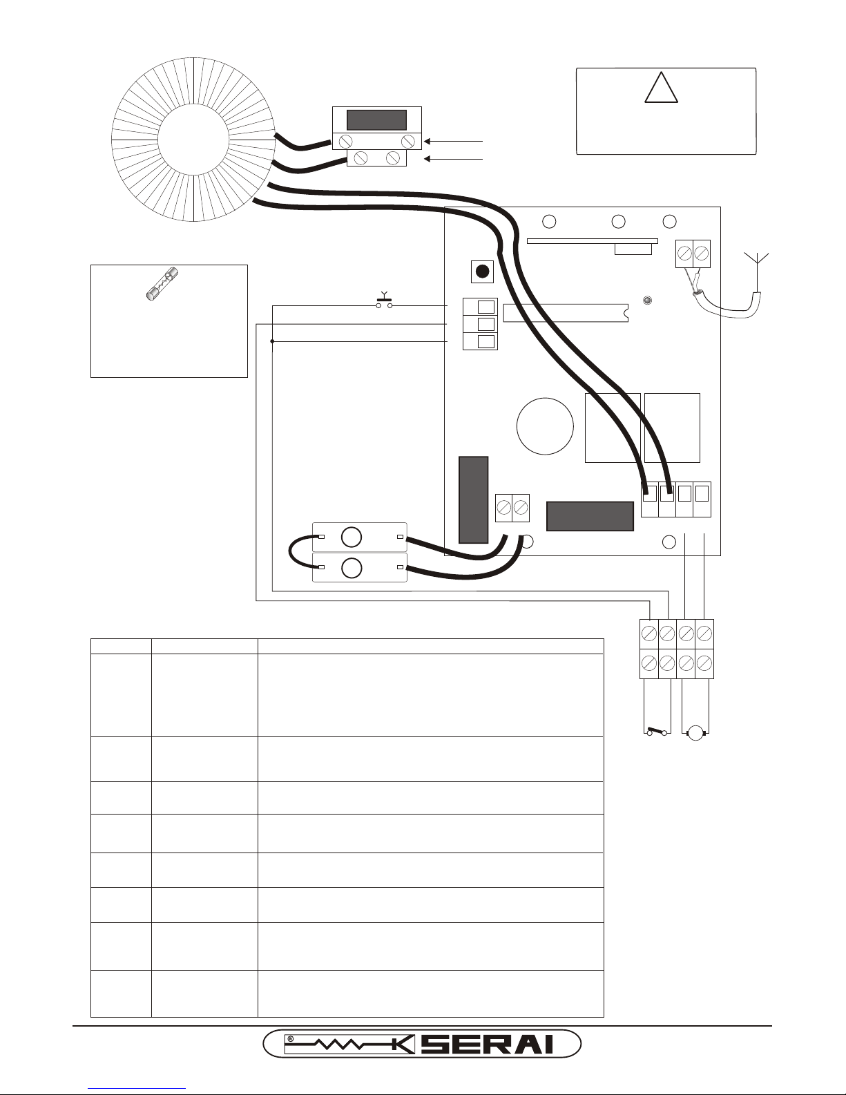
CR/53 CONNECTIONS LAYOUT
NC
LIMIT SWITCH
CLOSING
MOTOR
TERMINAL BOARD
MP/30 MOTOR
10 11
1 2
3 4 5 6
7 8 9
F2F2
F1F1
GND
(BRAID)
ANTENNA
+ -
NA
START
+
-
2 Batteries
12Vdc 2Ah
OPTIONAL
1
2
+
-
BATTERY
RED
BLACK
M1
WHITE
WHITE
230V~ ±10%
50/60Hz
F
N
12
F3F3
13
P1
DL1
230Vca ±10% 50/60 Hz, Hz power supply input, which via fuse
F3 powers the primary of the toroidal transformer
- already wired -
Motor power supply 24Vdc output
Start control input (NO contact) controls the opening and closure
with inversion during movement.
Common input terminals
Input for the connection of the antenna for the built-in receiver. For
normal capacity, the calibrated wire already connected is sufficient.
(10=BRAID/GND, 11=ANTENNA)
20Vac-24Vdc input for power supply of the circuit board
supplied via a toroidal transformer- already wired-
Input for the connection of 2 12V 2Ah buffer batteries
(optionals, e.g. SERAI BT/20) to guarantee functioning of the
automation in the case of a power cut. In presence of the
circuit board network voltage, it recharges the batteries via the
built-in battery-charger.
Closure limit switch input (NC contact)
DEFINITION OF THE CLAMPS
CLAMPS
CONNECTIONS
DESCRIPTION
12 - 13
NETWORK
POWER SUPPLY
5 - 6
MOTOR
8
7
START
CONTROL
COMMON
INPUTS
10 - 11
BUILT-IN
RECEIVER
ANTENNA
9
3 - 4
TRANSFORMER
SECONDARY
INPUT
1 - 2
OPTIONAL
BATTERIES
CLOSURE
LIMIT SWITCH
!
DIS
CONNEC
T THE POWER SU
PPLY
-FR
OM
THE NE
TWO
RK AND THE
BATTERY
ID PRESENT
, BE
FORE
INT
ERV
ENING ON THE CONNE
CTI
ONS
F1 = F5A 250Vca -instant-
-BOARD INPUTF2 = F5A 250Vca -instantaneous-
-BATTERYF3 = T1,6A 250Vca -delayed-
-PRIMARY TRANSFORMER-
DAL 1965
Pag. 5/7
KIT/45 I E
Page 6
BEHAVIOUR WHEN
STRIKING AN OBSTACLE
FOLLOWING THE
INTERVENTION OF THE
MOTOR SHUTDOWN
CONTROL
during closing (up)
before limit switch
during opening
(moving down)
The motor stops and inverts for 0.25s.
The motor stops and inverts until completely open.
BATTERY FUNCTIONING
If there is a power cut, the system continues to function with the batteries, if they are connected, without any difference in operation.
When the mains voltage returns, the built-in battery charger charges and maintains the batteries in this state.
24 hours are required for complete re-charging.
DELETING CODES IN THE MEMORY
The deleting of all radio codes memorised is carried out by pressing and holding the P1 key until the DL1 LED
switches off (about 10s) without sending any radio code.
LEARNING THE RADIO CONTROL CODE
The circuit board incorporates a 433.92 MHz radio receiver which allows to control the motor at a distance via
micro switch remote controls of the OG/02, OG/04 series and self-learning remote controls of the OG/62, OG/64,
OG/28, OG/48, OG/52, OG/54, OG/82/1 and OG/84 series.
!
ATTENTION:
- before using a remote control, perform the programming procedure.
- a maximum of 10 codes can be memorised.
- before starting first programming or deleting the remote controls, temporarily disconnect the
antenna to prevent the receiver from acquiring other signals during this phase, which may cause
incorrect functioning of the automation. Re-connect the antenna when the procedure has ended.
LEARNING START CODE
- With the control unit powered press the P1 key once to enter programming. The DL1 LED starts to flash to
indicate that the control unit is in the programming state.
- Press the remote control button (e.g. on the left) and hold down until the DL1 LED switches off. The control unit
has memorised the radio code received and automatically leaves programming, setting itself for normal
functioning.
- Repeat the procedure if several remote controls must be memorised.
1
2
3 4
5
6
7
8
9 1
0
12
3
4
5
6 7
8
9 1
0
!
MODIFY THE FACTORY
CONFIGURATION TO PREVENT
UNDESIRED CONTROLS
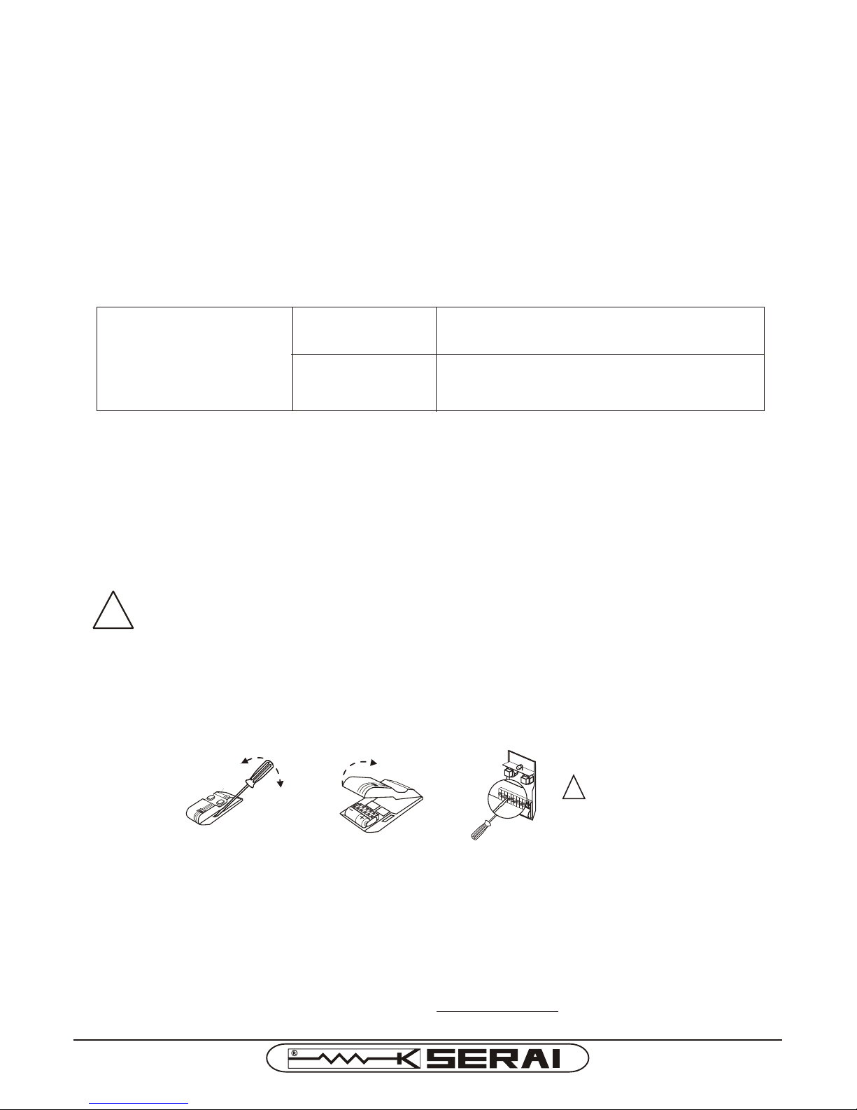
CONFIGURATION OF MICRO SWITCHES ONLY IN THE CASE OF OG/02 AND OG/04 REMOTE CONTROLS
Only if OG/02 and OG/04 remote controls with micro switches are used, before performing learning of the codes on
the receiver, the factory configuration of the micro switches must be modified to prevent undesired controls.
MOTOR SHUTDOWN CONTROL
The control unit has "shutdown motor" control able to intervene when the motor remains completely at a standstill
for a couple of seconds. It is a control that cannot be regulated or excluded which is used to identify stops and
motor blocks during the normal run.
.
STANDARD OPERATION OF MOTOR BOARD
- With the motor closed (upright position with limit switch active) a start control moves the motor down (opens).
- With the motor open (horizontal position with limit switch deactivated) a start control moves the motor up (closes).
- With the motor closing (moving up) a start control inverts motion until it opens completely.
- With the motor opening (moving down) a start control inverts motion until it closes completely.
- When fully opened/closed, there is a 0.25s motion inversion to reduce pressure and facilitate release.
- The 1st manoeuvre is closing (up) if the limit switch is not active, while it is opening (down) if the limit switch is active.
INDICATION OF RED DL1 LED
When the board switches on, the LED flashes twice.
Subsequent flashes indicate the reception of a radio signal or other various programming phases.
DAL 1965
Pag. 6/7
KIT/45 I E
Page 7
TROUBLESHOOTING
PROBLEM CAUSE
SOLUTION
The motor reducer
does not work
No voltage
to the motors
Check the presence of voltage at the motor power supply input
terminals.
Check that the power supply cable is not interrupted. (the power
supply cable must be replaced by an authorised technician).
Check the fuses on the control unit.
Motor connection
inverted
Check electrical wiring between control unit and motor.
No voltage
to the control unit
Check the network fuse and the presence of network voltage.
Check the voltage of the battery - if present-
Motion inversion
when fully open
The motor does not
complete opening
but blocks
beforehand
The motor inverts
motion while closing
before meeting
the limit switch
Check manually to make sure the whole stroke of the motor
moves regularly.
KIT/45 I E 01 07 110608 A4Vf/r -IS KIT45-E
Intervention
of motor
shutdown control
Check manually to make sure the whole stroke of the motor
moves regularly.
Intervention
of motor
shutdown control
TECHNICAL DATA OF THE CR/53 CONTROL UNIT
Power supply transformer: 230/20 Vac, 130VA
Internal battery charger capacity: 28Vdc, 0.5A
Optional battery capacity: 2x12Vdc 2Ah
Motors power supply: 24Vdc 4A
Operating temperature: -20°C ÷ +60°C
Dimensions (H x L x D) and weight: 270x212x118mm, 2.4Kg
Inversion of motion
when completely
closed (after
meeting limit switch)
Limit switch does
not intervene
Check connection and/or functioning of closing limit switch.
INFORMATION FOR USERS CONCERNING WASTE DISPOSAL OF THIS APPLIANCE (WEEE)
in compliance with art. 13 of the Legislative Decree of 25/07/2005, n. 151 "Implementation of Directives 2002/95/EC, 2002/96/EC and 2003/108/EC, relating to the reduction of the use of
dangerous substances in electrical and electronic equipment, as well as waste disposal".
This device was manufactured after 13/08/2005. The symbol of the crossed-out wheeled bin, applied on the device itself or on its packaging, indicates, for the safeguard of the environment, that at the end of
its useful life the device must not be disposed of as common city waste, but must be gathered separately. The user must therefore bring it to a suitable differentiated waste collection facility for Waste of
Electric and Electronic Equipment (WEEE), or else send it back to the dealer when purchasing a new equivalent model, replacing one with the other. Adequate differentiated waste collection for subsequent
sending of the dismantled device for recycling, processing and environmentally compatible waste disposal helps avoid negative effects on the environment and on health and favours reuse and/or recycling
of the materials which the device is made of. Illegal waste disposal by the user entails the application of sanctions foreseen by standards in force.
CE DECLARATION OF CONFORMITY
SERAI spa declares that the KIT/45 product has been designed and realised with respect to the Directives and Standards stated above.
WARRANTY CONDITIONS
The company reserves the right to make any modifications without forewarning. The conventional guarantee of SERAI product is valid for 24 months from the date of issue of the fiscal document, which proves purchase
and is applied in the seat of Legnaro - PD - or at authorised After-sales Centres. The transport costs are under the Customer's responsibility. The warranty terminates in the event of tampering with or removal of the label
specifying the manufacturing lot of the product and in the event of tampering with the product itself.
MADE IN ITALY
VIA ENRICO FERMI, 22
35020 LEGNARO - PADOVA
I T A L I A
+39 049 79 08 58
+39 049 88 30 529
[email protected]
www.serai.com
ELETTRONICA PADOVA
DAL 1965
 Loading...