

Page 1
DAL 1965
KIT/18F -SR 24.19F KIT FOR SLIDING GATES UP TO 1800 kg - 230/400 V~
KIT/25H -SR 24.24 MOTOR WITH CONTROL UNIT FOR SLIDING GATES UP TO 2500 kg - 230/400 V~
MOTOR WITH CONTROL UNIT FOR SLIDING GATES UP TO 1800 kg - 230/400 V~KIT/18H -SR 24.20
Pag. 1/10
KIT/18F-18H-25H I E
Thank you for choosing a SERAI ELETTRONICA product, which we are confident will perform to your requirements.
Please be advised that you are about to fit a system classified as “a power-operated drive designed to move automatic
gates and doors in commercial or residential buildings accessed by vehicles and persons”, and, as such, the system
must be considered potentially hazardous. By law, you are responsible for rendering this equipment as “safe” as is
reasonably possible.
Installation and maintenance of equipment of this kind must therefore be carried out by skilled, qualified and trained
personnel, working in a professional manner, as provided for by law n. 46/90 and subsequent amendments and
supplements thereto. The law in question prohibits the construction of these types of systems by non-qualified
personnel.
SERAI manufacturing complies with the following legislation:
Applicable directives for the CE marking:
Machines: 98/37/EEC
Low voltage: 73/23/EEC
Electromagnetic compatibility: 89/336/EEC
R&TTE (Radio and Telecommunications Terminal Equipment): 99/5/EEC
General applicable standards:
Electrical safety: IEC EN60335-1 + IEC EN60335-2-103
Electromagnetic compatibility - emissions: IEC EN61000-6-3
Electromagnetic compatibility - immunity: IEC EN61000-6-1
Apart from the legislation mentioned above, you are also reminded to comply with the following standards during the
installation phase.
General applicable standards:
Safety of electrical systems in non-specialised environments: CEI 64-8
Specific product standards applicable:
Safety in the use of power-operated doors requirements: UNI EN12453
Safety in the use of power-operated doors testing methods: UNI EN12445
SERAI products enable users to build systems which comply with these standards. This is extremely important as
THE INSTALLER IS LIABLE FOR THE SYSTEM AND FOR ENSURING ITS OPERATION COMPLIES WITH
LEGAL PROVISIONS.
This handbook must be read in full, at least once, before proceeding with the installation of the various parts
of the system.
The installation of the mechanical end stops for gate opening and closure is necessary for system safety
purposes and therefore this operation must be performed before proceeding with the installation of the
control unit.
!
E R A IS
GATE AUTOMATION DIVISION
INSTALLATION MANUAL
Page 2
DAL 1965
Pag. 2/10
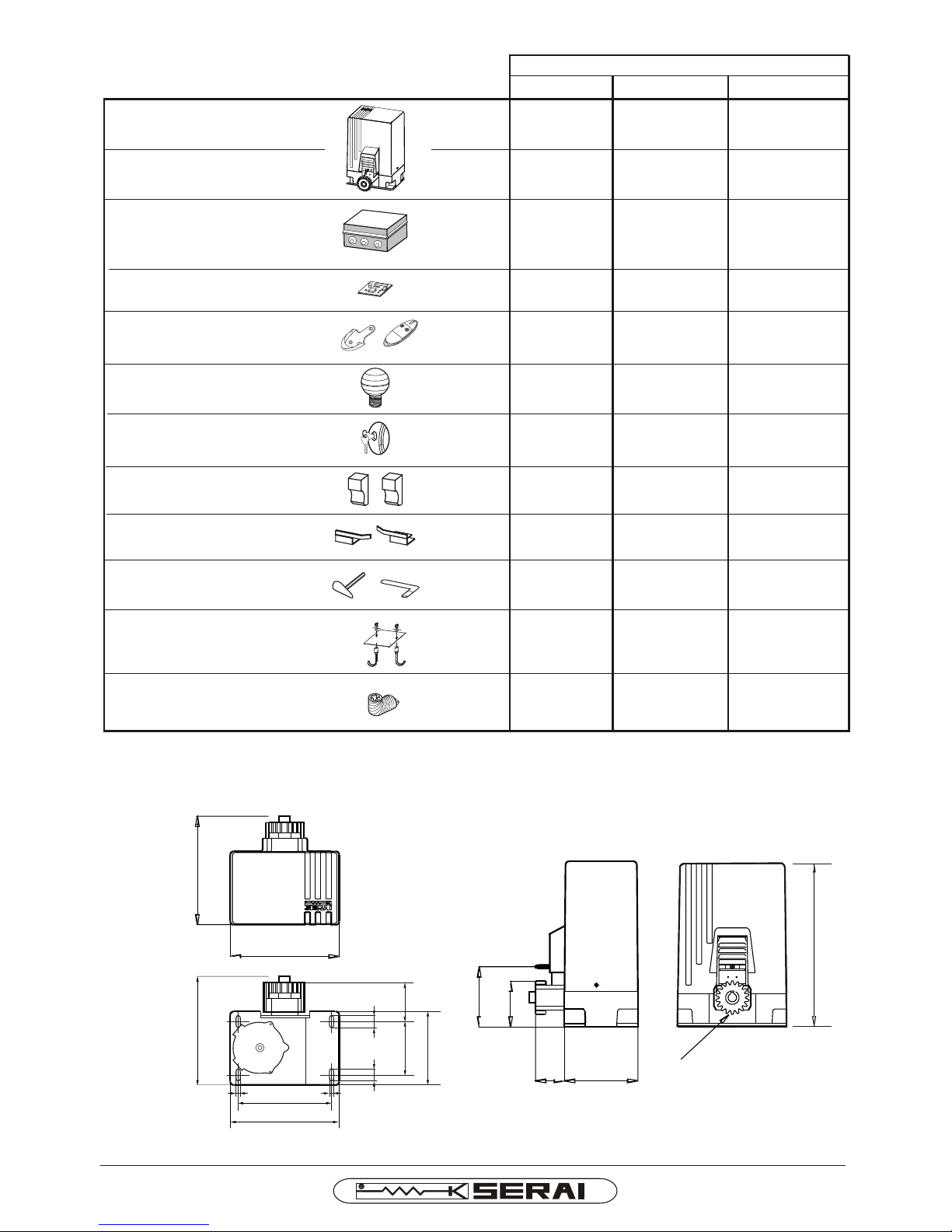
250
144
110
265
66 180
Z18 M4
400
250
265
130 91
232
14
14
30 30
180
DIMENSIONS OF THE MOTOR
Motor MT/18
Motor MT/25 with
inside fan
Electronic control
panel CR/14
Radio receiver
card SOG/4A
Minitransmitter
OG/62
Flasher with
antenna RZ/07/1F
Electric key
M/10
Pair of
photocells P/94
Pair of limit switch
slide blocks
Release key
Key for clutch adjustment
Base plate PM/13
Elbow support
KIT/18F KIT/18H KIT/25H
X X
X
X
X X
X
X
X X
X X
X
COMPONENTS OF THE KIT
X
X
X
X
X
X
KIT/18F-18H-25H I E
Page 3
DAL 1965
Pag. 3/10
6
7
8
9
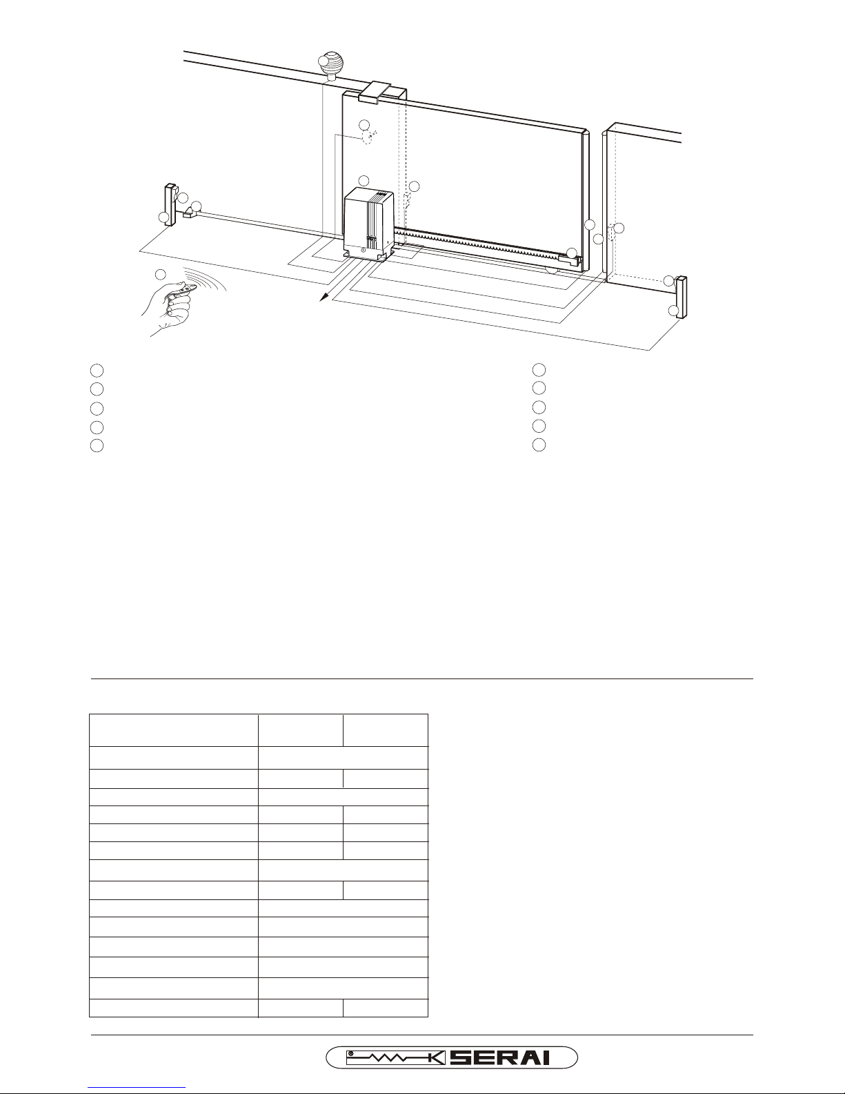
10 Minitrasmitter
Electric key (selector)
Columns for photocells
Photocells for internal use
Stop block
4 x
0,5 mm
²
3 x
1,5 mm²
2 x
0,5 mm
²
3
x
0,
5
mm²
R
G
5
8+
2 x
0,
7
5
mm²
2 x 0,5
mm
²
2 x 0,5 mm
²
4
5
STANDARD INSTALLATION
1
2
3
4
5
Geared motor + electronic control panel + radio receiver card
Photocells for external use
Limit switch slide blocks
sensitive edge
Flasher with antenna
7
8
400 V~
7
8
4x0,5 mm²
3
6
1
2
9
2
4
2 x
0,5
mm
²
10
irreversible
400/230 V~ ±10% 50/60 Hz
IP54
-20 °C ÷ +60 °C
265 X 250 X 400 mm
with mechanical clutch
+ 150°C
1:30
MT/18 MT/25
2500 Kg
1800 Kg
1,6 A
1050 W
1200 N
1 A
660 W
1200 N
10,5 m/min
10,5 m/min
18,5Kg 19Kg
TECHNICAL DATA OF THE GEAR MOTOR
The motor MT/25 is equipped with inside fan drived
by a thermal device and with cooling lateral grids on
the casing.
The electric fan is activated when the motor
temperature goes over the 50°C.
Advice for wiring up in non-specialised environments.
1. Fit an omnipolar switch upstream of the system, choosing one with a gap of at least 3 mm between the contacts. Or,
alternatively, use a 10A magnetothermic switch.
2. When making the connections (using any type of connector), ensure the system is disconnected from the power
supply, i.e. that the main switch is in the “open” position (“0” symbol). The control unit, in particular, must never be
connected to the power supply either during the wiring up, or when fitting any expansion cards.
3. The following cables must be used for installation of the system:
22
- for the control unit and motor power supplies: 1.5 mm section for lengths of up to 19m, 2.5 mm section for
lengths of up to 31 m,
22
- for the flashing light: 0.75 mm section for lengths of up to 3 m, 1.5 mm section for lengths of up to 19 m.
- for the low voltage and current lines (e.g. For the photocells, control buttons, electromechanical key, sensitive
22
edges and other safety devices): 0.5 mm section for lengths of up to 50 m, 0.75 mm section for lengths of up to
100 m.
4. Wire up the earth connection in compliance with legal provisions.
Motor type
Dimensions
Max gate weight
Power supply
Absorbed current
Absorbed power
Traction and thrust force
Motor power adjustment
Gate speed
Motor thermal protection
Gear ratio
Protection class
Operating temperature
Weight
KIT/18F-18H-25H I E
Page 4
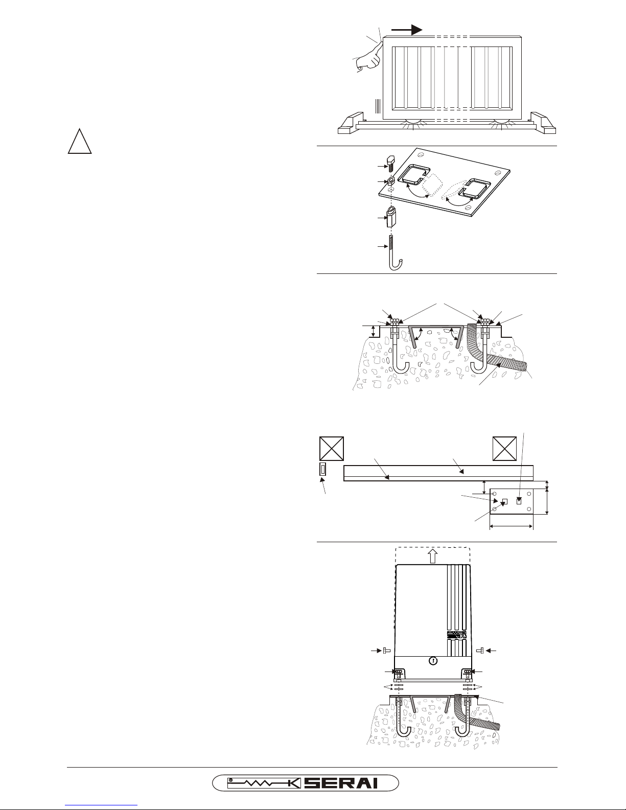
Fig. 1
Fig. 2
Fig. 3
Fig. 3a
A
B
F
C
E
Z
Z
72
47
170
270
50
F
A
F
A
aa aa
Fig. 4
SS
FF
VV
!
DAL 1965
Pag. 4/10
4) INSTALLATION OF THE GEARED MOTOR
- After the concrete has solidified, loosen the nuts A
and unscrew the screws F (Picture 3).
- Unscrew the two side screws V and remove the
casing (Picture 4).
- Fasten the geared motor to the base plate PM/13
through the screws F after removing the nuts A. Take
care to put some distance washers S, 2 mm thick, (2
pieces each screw) between the base plate and the
base of the geared motor in order to adjust the gap
between the pinion and the rack (Picture 4).
3) FIXING OF THE BASE PLATE
- Prepare an excavation where to cement the geared
motor base plate PM/13.
- Place the base plate PM/13 respecting the spaces as
shown in the pictures 3÷3a (we advise you to let it jut
out about 50 mm from the ground).
- The base where to fix the base plate should be clean
and perfectly parallel to the ground.
- Prepare some flexible tubes for the passing of the
electric feeders making them pass through the hole of
the base plate (Picture 3a).
2) SETTING OF THE BASE PLATE PM/13 FOR THE
FIXING OF THE GEARED MOTOR:
Insert the nut C in the 4 holes of the base plate B.
- Screw the tie-rod E to the nut C until it stops, Picture 2.
-
- Screw the nuts A to the screws F, Picture 2.
- Screw the screws F so pieced together to the nuts C
and lock the base plate B tightening the nuts A, Picture
2. Repeat the operation for the other holes of the base
plate PM/13.
- Bend downwards the preformed rag bolts Z by means
of a hammer or some pliers until you get an angle a <
90°, Picture 3.
1) BEFORE BEGINNING THE INSTALLATION OF THE
GEARED MOTOR
- Check that the gate is provided with a rugged rail.
- Check that the rail is well fixed in the ground.
- Check that some rugged stop blocks are fixed at the
further ends of the rail.
- Check the perfect smoothness of the gate.
The installation of the mechanical end stops
for gate opening and closure is necessary for
system safety purposes and therefore this
operation must be performed before
proceeding with the installation of the control
unit.
NUT M10 TO BE USED JUST FOR THE TIGHTENING OF
THE BASE PLATE DURING THE CEMENTATION PHASE
BASE PLATE
TUBE FOR THE PASSING
OF FEEDERS
RACK
GATE
HOLE FOR THE
FEEDER ENTRY
STOP BLOCK
BASE PLATE PM/13
HOLE THAT HAS NOT TO BE
USED FOR THE FEEDER ENTRY
BASE PLATE
KIT/18F-18H-25H I E
Page 5
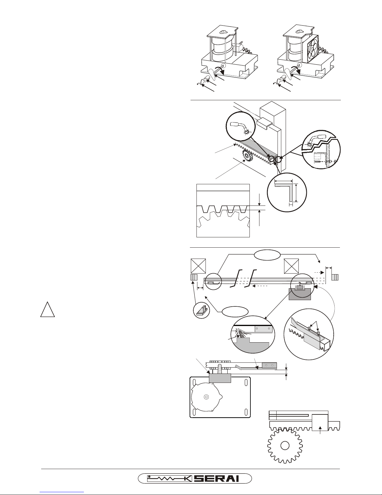
Fig. 5
Fig. 6
40mm
40mm
5 mm
RACK
GAP OF
ABOUT
2 mm
PINION
RACK
PINION
!
15 ÷ 25 mm
P
Z
Fig. 7A
80 mm
80 mm
CLICK!
P
P
CLICK!
M
H
Fig. 7B
MT/25
MT/18
KEY
DAL 1965
Pag. 5/10
6) FIXING OF THE LIMIT SWITCH SLIDE BLOCKS
- Make the gate slide by hand up to
approximately 80 mm from the stopping point
(mechanical stop block) either on closing or on
opening.
- Fix the slide block P to the rack by means of
the grub screws H placing it so as to make it
operate the spring M for the driving of the
micro-switches (Picture 7). Repeat the
operation from the opposite side.
Remember that the slide blocks have to be adjusted so that during its working the gate does not
slam against the stop blocks both on closing and
on opening, otherwise the mechanical parts
of the geared motor can be damaged
ATTENTION:
Observe the distance of 15 ÷ 25 mm between
the limit switch slide blocks P and the frontal
edge Z of the spring outlet (Picture 7B). A
distance higher than 25 mm could make the
gate stop in the position open or closed. A
distance inferior to 15 mm could cause make
the spring break.
Pay attention that the pinion does not clash
against the clamp S of the limit switch slide
block (Picture 8).
-
-
Remember that the stop point of the gate after
the end run intervention depends:
a) on the weight of the gate
b) on the sliding speed
c) on the frictions
d) on the temperature
The a and b features are constant, whereas
the c and d are variable and, in time, amend
the stop point of the gate.
LIMIT SWITCH
SLIDE BLOCK
S
PINION
Fig. 8
5) INSTALLATION OF THE RACK
- Release the motor. Insert the key in the
cylinder, give it half a turn anticlockwise and
then take key and cylinder out. Insert the
hexagonal release key and turn it clockwise
until it stops (Picture 5).
- Solder the rack to an iron angle bar (ex: 40 ×
40 × 5 mm) (Picture 6).
- Put the rack forepart into gear with the pinion
and fix it to the gate through screws or
soldering, repeat these operations in various
points, so that when the gate is moved by hand
the rack rests on the pinion (Picture 6).
- Once this operation is finished, adjust the gap
between pinion and rack taking the washers S
away, so that a constant gap of about 2 mm is
kept between the pinion and the rack when the
gate is moved by hand.
We advise you to let a washer S for each screw
so as to make up for incidental lowerings of the
gate.
- Adjust the geared motor in a horizontal sense
so that the pinion is put into gear with the rack
for all the length of the tooth.
- Tighten the clamping screws F of the geared
motor to the base plate.
CYLINDER
RELEASE KEY
KEY
CYLINDER
RELEASE KEY
KIT/18F-18H-25H I E
Page 6
!
Fig. 9
CYLINDER
KEY
Fig. 10
-
+
DAL 1965
Pag. 6/10
!
MT/25
-
+
MT/18
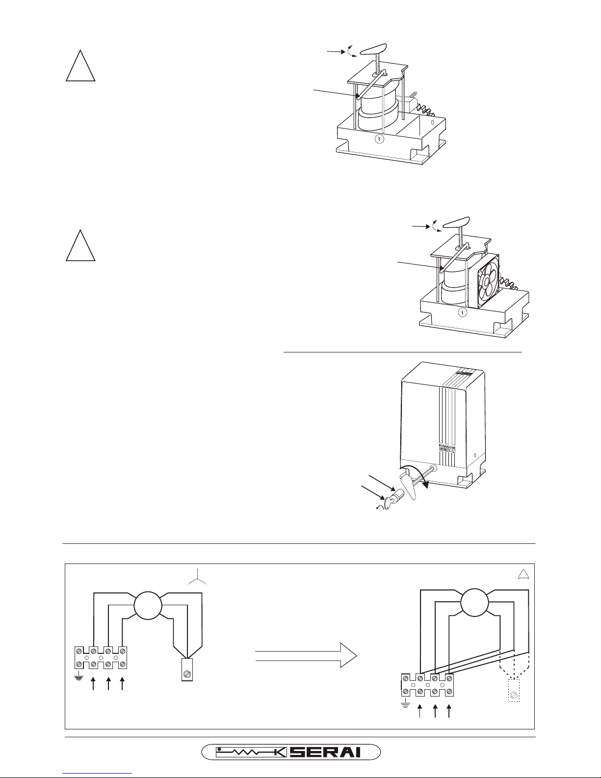
MOTOR TRANSFORMATION FROM 400V~ THREE-PHASE -in factory- TO 230V~ THREE-PHASE
R
S T
M
BLUE
BROWN
BLACK
400 V~ THREE-PHASE
BLUE
BLACK
R
S T
M
BLUE
BROWN
BLACK
230 V~ THREE-PHASE
BLUE
BROWN
BLACK
BROWN
STAR CONNECTION
FOR 400V~
DELTA CONNECTION
FOR 230V~
JOINT CLAMP
FACTORY
SETUP
REMOVE THE
JOINT CLAMP
REMOVE THE
JOINT CLAMP
Fig. 11 Fig. 12
7) ADJUSTING OF THE MOTOR POWE
ATTENTION: Turn power supply off, the
motor could be accidentally started up
while the friction is being adjusted.
a) Insert the release key in the hexagonal opening
of the driving shaft.
b) Insert the flat key in the opening on the motor
flange so as to block the driving mast ring nut.
c) Keep the flat key blocked, turn clockwise the
hexagonal key in order to reduce the motor
power and anticlockwise to increase it.
d)Take the two keys out and give power supply in
order to check if the motor power is the
appropriate one, otherwise repeat the
operations.
Remember that the strong differences in
temperature between summer and
winter cause different expansions in all
the materials. We advise you to check
again the setting of the motor thrust
power from time to time, keeping it within
the security regulations in force.
e) Replace the casing and fix it through the two side
screws.
ATTENTION:
8) EMERGENCY MANOEUVRE
a) Insert the key in the cylinder, give it half a turn
anticlockwise and pull the cylinder out (Picture 10).
b) Insert the hexagonal release key, turn it clockwise
until it stops (Picture 10).
c) The gate can be moved by hand.
In order to block again proceed in the opposite
direction.
d) Turn the hexagonal release key anticlockwise until it
stops (without forcing).
e) Insert the cylinder and give the key half a turn
clockwise. Take the key out.
We advise you to perform once a month an emergency
manoeuvre.
FLAT KEY
HEXAGONAL
RELEASE KEY
KIT/18F-18H-25H I E
FLAT KEY
HEXAGONAL
RELEASE KEY
Page 7
!
DAL 1965
Pag. 7/10
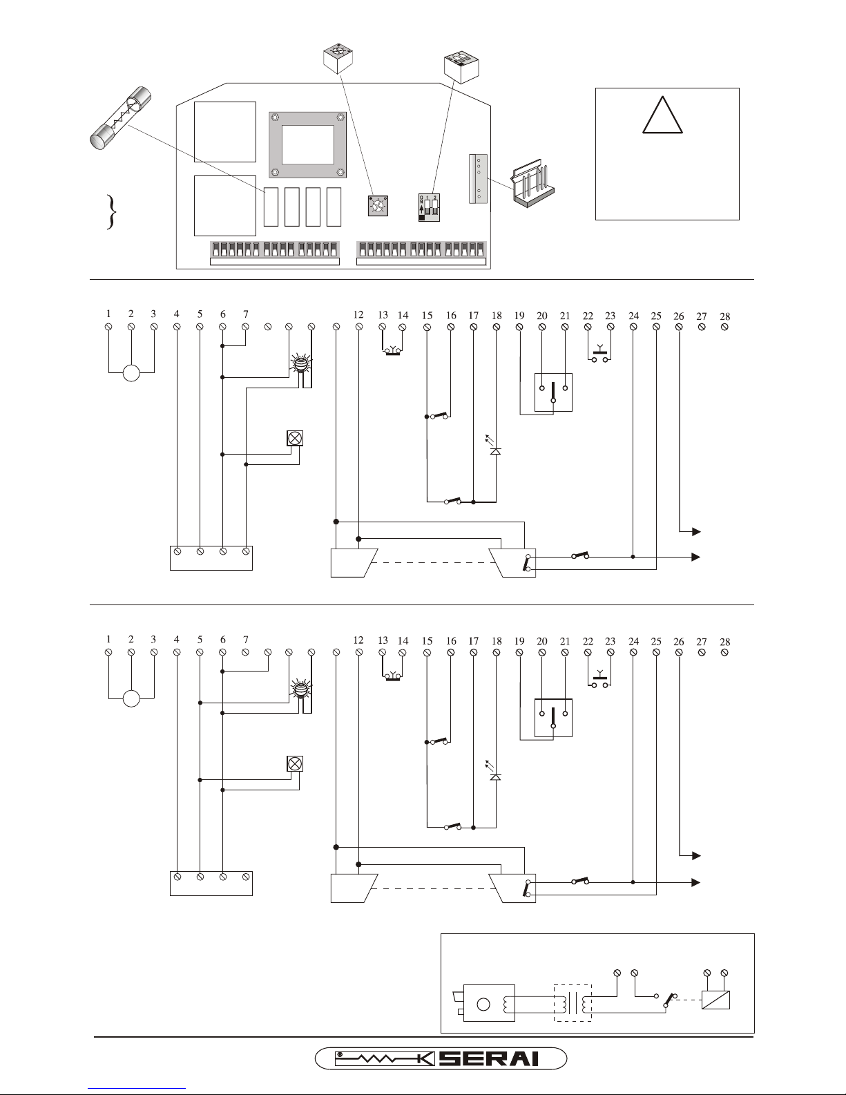
WIRING DIAGRAM CR/14 PER 400V~ -factory setup-
WIRING DIAGRAM
T1
TRIMMER
DIP-SWITCH
FUSE
F1
F2
F3
F4 500mA 250V~
CN 1
F1 F2 F3 F4
CR/14
5A
250V~
98
OPEN
CLOSE
M
R S T
10 11
NO
MOTOR 400 V~
THREE-PHASE
-see Fig.11-
FLASHING LIGHT
230V~ single-phase
TRANSMITTER
PHOTOCELL
RECEIVER
GATE
OPEN
INDICATOR
COMMON
OPEN/
CLOSE
STOP
NC
NC
NC
NC
CN 1
24 V~
MAX 300 mA
POWER SUPPLY
400 V~ THREE-PHASE
24 V-
-
+
SENSITIVE EDGE
NC
R S T N
ELECTRIC NETWORK
400V~ three-phase+neutral
WIRING DIAGRAM CR/14 PER 230V~ THREE-PHASE
98
M
R S T
10 11
STOP
NC
NC
NC
NC
24 V~
MAX 300 mA
MOTOR 230 V~
THREE-PHASE
-see Fig.12-
NC
R S T N
ELECTRIC NETWORK
230V~ three-phase+neutral
24 V-
-
+
* ELECTRIC LOCK
230V~
24(+) 26(-)
RELE'
24 V
TR/01
SR 19.61
* OPTIONAL ELECTRIC LOCK
12 V~
INSIDE FAN
230V~ single-phase
-only MT/25-
DI
SC
ONNE
CT THE
POWER
SUP
PLY
BE
FO
RE
WOR
KI
NG
ON T
HE
WIRIN
G
OPENING
LIMIT SWITCH
CLOSURE
LIMIT SWITCH
OPEN
CLOSE
NO
COMMON
OPEN/
CLOSE
OPENING
LIMIT SWITCH
CLOSURE
LIMIT SWITCH
TRANSMITTER
PHOTOCELL
RECEIVER
SENSITIVE EDGE
FLASHING LIGHT
230V~
INSIDE FAN
230V~ -only MT/25-
POWER SUPPLY
230 V~ THREE-PHASE
* ELECTRIC LOCK
KIT/18F-18H-25H I E
GATE
OPEN
INDICATOR
Page 8
GROUND CONNECTION BETWEEN MOTOR AND HOUSE-PLANT
DAL 1965
Pag. 8/10
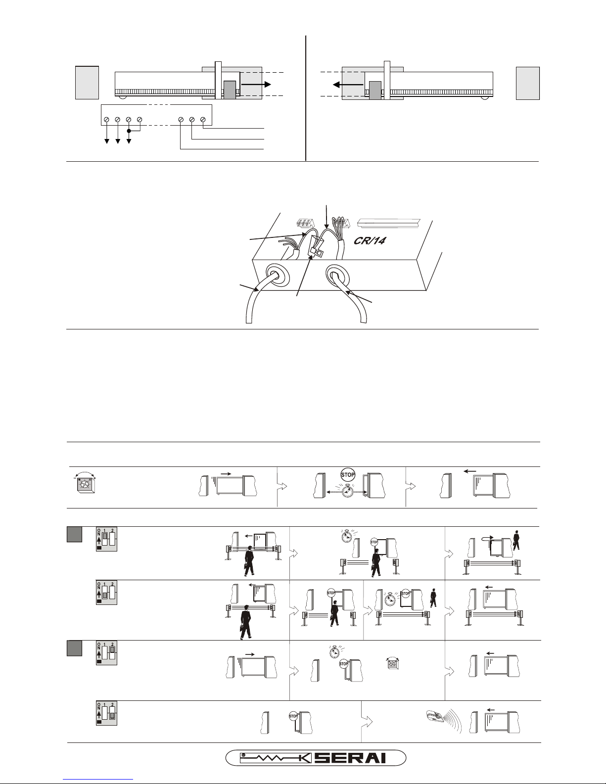
MOTOR CONNECTIONS
CR/14
4 5 6 7
R S T
15 16 17
BLUE
BROWN
BLACK
MOT
O
RE
MO
TORE
4 5 6123
CR/14 TECHNICAL DATA
Dimensions................................. 235x155x90 mm
Temperature.............................. -20° ÷ +60°C
Weight.......................................... 1,3 kg
Power supply............................ 230/400V~±10% 50/60 Hz
:
max.power supply / voltage..........1100W / 400 V~
Remote control switches for three-phase motors
WORKING SET-UP
5 ÷ 100 s
Gate open
pause
T1
2 s
11
reverse direction automatic restart
after stopping from photocell drive
on closing action
ON
OFF
2 s
automatic restart in the same
direction after stopping from
photocell drive
22
ON
T1
5 ÷ 100 s
OFF
DIP SWITCH SET-UP
TRIMMER
MOTOR ON THE RIGHT (FACTORY SETUP)
MOTOR ON THE LEFT
To connect the motor on the left-hand side of the
gate, swap the following connections:
4 with 5
16 with 17
MOTOR YELLOW-GREEN CABLE
MOTOR CABLE
CONNECTING CLAMP
CABLE THREE-PHASE 400 V~
POWER SUPPLY
YELLOW-GREEN CABLE
automatic reclosure
manual drive reclosure
KIT/18F-18H-25H I E
Page 9
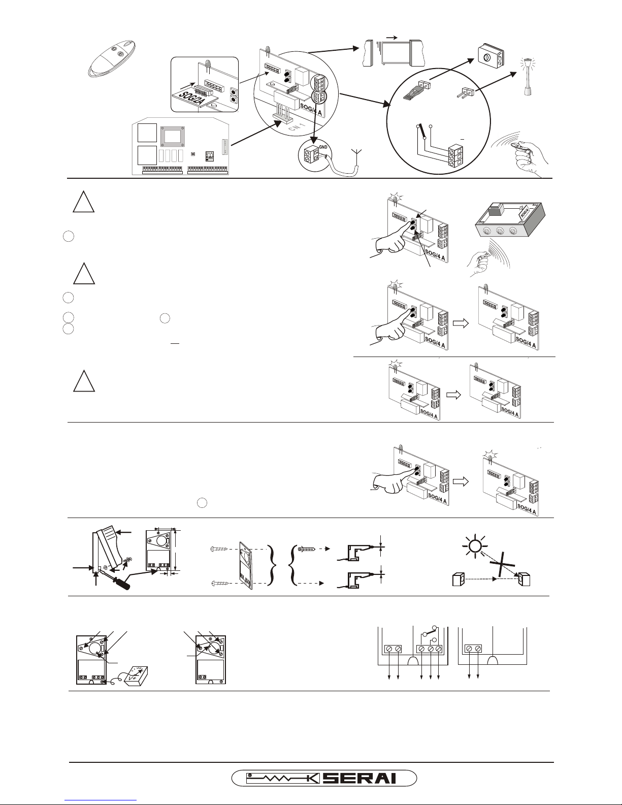
NO
1A 24 V~
NC
DAL 1965
Pag. 9/10
F1 F2 F3 F4
CR/14
CN 1
ANTENNA
!
LED ON
LED OFF
!
!
LED OFF
NO!
Ø 6mm
Ø 3,5mm
87 mm
29 mm
19 mm
TX RX
PHOTOCELLS P/94
ALIGNING
ELECTRICAL CONNECTIONS
ADJUSTING SCREWS; RECEIVER LED IS ON ONLY
WHEN THE LIGHT BEAM IS ALIGNED
3,5V- MIN!
(LED = ON)
LED
CONTACT STATE IS RELATED TO
ALIGNED LIGHT BEAM CONDITION
RECEIVER TRANSMITTER
(24V@) (1A / 24V@) (24V@)
TECHNICAL DATA
Power supply 24V@ ±10%
TX load 28mA a 24 V-
50 mA a 24 V~
RX load 17 mA a 24 V-
40 mA a 24 V~
External range 25 m
Indoor range 50 m
N. 2 relais 1 switch 1A / 24 V@
Temperature -10 ÷ +60 °C
Dimensions/weight 58 x 104 x 44 mm / 220 g
LED
RADIO CONTROL 433,92 MHz
MEMORY EXPANSION
FROM N°40 TX TO N°834
1° CHANNEL
2° CHANNEL
MONOSTABLE
FUNCTION
BISTABLE
FUNCTION
LIGHTS
ELECTRIC LOCK
RADIO CARD PROGRAMMING
ATTENTION: before using each minitransmitter it is
necessary to execute the procedure for the receiver
programming
1 keep pressed the button of the chosen channel for 1 sec., the led
will flash and then it will remain fix.
ATTENTION: do not keep pressed the button for 5 sec.
or more, the already stored codes will be erased.
4 keep pressed the button on the receiver for 1 sec in order to exit
from the programming or wait 2 minutes the red led has to switch
off.
when the number of available codes per canal -40 or
834- is exhausted the receiver exit automatically from
the programming
PROGRAMMING RESET
if you want to reset the programming of one of two channels,
keep pressed the button of the relevant channel for 5 sec.the red
led will light up fix.
HOW TO ADD NEW TRANSMITTERS
repeat the operations from the 1 point.
2 press the transmitter in order to send the signal, the led will flash
and then it will remain fix: stored code
3 repeat the operation 2 for storing other transmitters
1° CHANNEL
2° CHANNEL
KIT/18F-18H-25H I E
Page 10
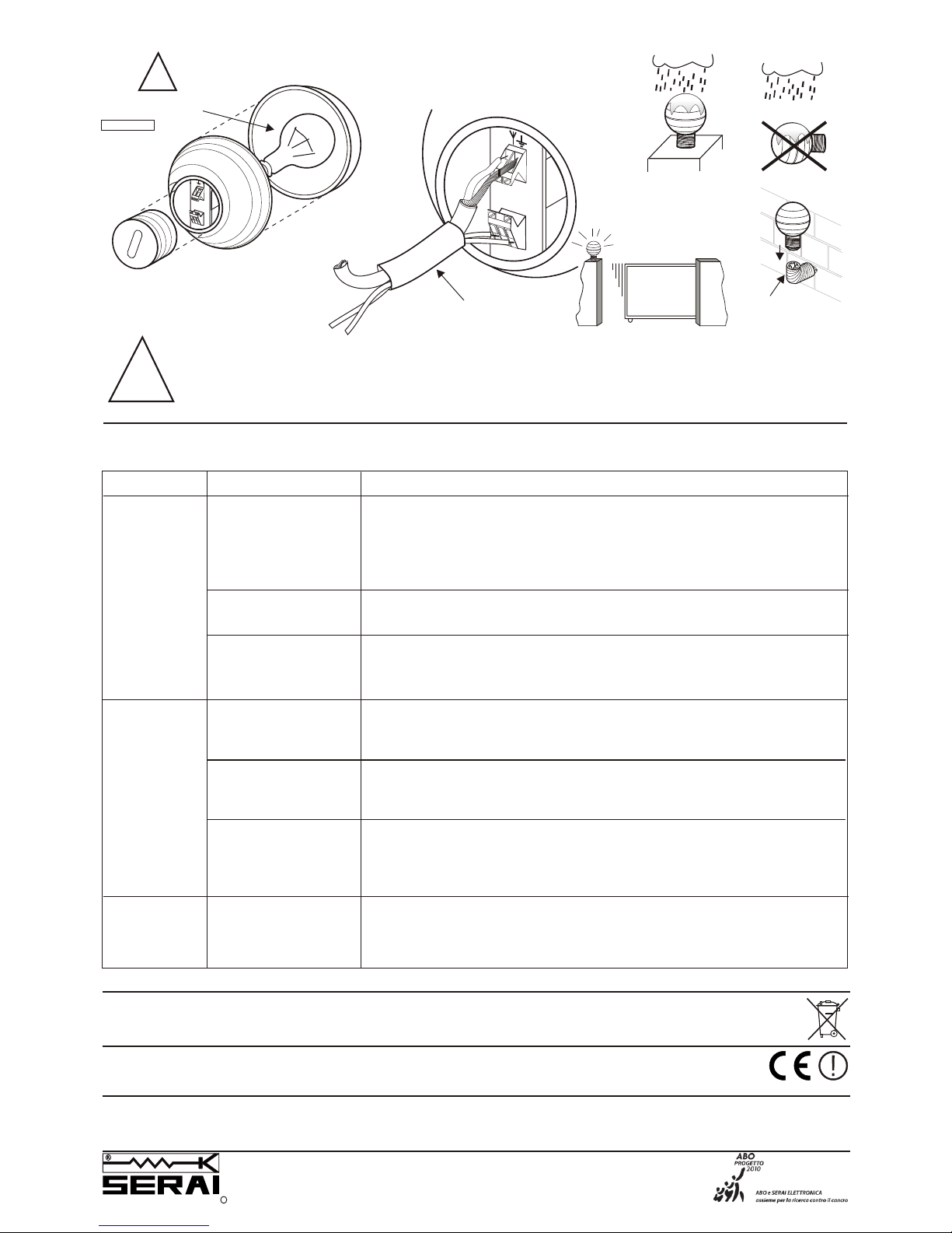
FAULT IDENTIFYING GUIDE
PROBLEM CAUSE
SOLUTION
FLASHING LIGHT RZ/07/1 F
!
NO
2 x 0,75 mm²
POWER SUPPLY
RG58
ANTENNA
CS/07 SR12.07
OPTIONAL CABLE
CONNECTIONS
230 Vac
OK
!
ATTENTION:
WE SUGGEST TO PLACE THE FLASHING-LIGHT FEEDER INSIDE AN INACCESSIBLE TUBE. ON THE CONTRARY,
ALL ACCESSIBLE PARTS HAVE TO GRANT A DOUBLE ISOLATION, MORE OVER IN ORDER TO AVOID THE TEAR OF
THE CABLE IT IS ADVISABLE TO USE A CABLE-HOLDER.
RZ/99 SR 10.99
ELBOW
SUPPORT
FOR REPLACEMENT,
USE LAMPS
240 V~ MIN ,
25 W E14
240 V~ MIN
The geared
motor does
not work
Faulty fuse
Change the fuse.
Power supply failure
- Check the presence of voltage at the power supply entry clamps to the
motor
- Check that the power supply cable is not cut off. The substitution of the
cable has to be carried out by an authorised technician.
The motor overheats
Stop the motor for 5 minutes and then try to make it work again.
Stop of the gate
Limit-switch set up
not correct
The gate
does not
complete its
run
Unlock the motor - see emergency monoeuvre - and move it by hand in
order to verify that there are no obstacles, if so, remove them. Picture
7A ÷ 7B.
Check the position of the limit-switch slide blocks and their working on
the spring for the micro-switch drive, adjust them.
Unsuitable
gearmotor position
Check that the distance between the end stop sliding plate and the front,
outgoing trim of the spring, adjust t hem.
The gate does
not startor the
motor slips
Clutch adjusting
not good
Take power supply off, and increase the setting of the motor power see point 7 ADJUSTING OF THE MOTOR POWER.
KIT/18F-18H-25H I E 02 10 090624 - A4Vf/r - IS KIT/18-25-I-E
ELETTRONICA PADOVA
I
SINCE 1965
MADE IN ITALY
VIA ENRICO FERMI, 22
35020 LEGNARO - PADOVA
I T A L I A
PHONE +39 049 79 08 58
FAX +39 049 88 30 529
E-MAIL [email protected]
WEB www.serai.com
TERMS OF GUARANTEE
The company reserves the right to make modifications to the equipment without prior notice thereof. SERAI products are covered by a standard guarantee with a term of 24 months.
Coverage starts on the date on which the tax document constituting proof of purchase is issued and guarantee services shall be provided on the company's premises at Legnaro - PD or at the Authorised Service Centres. Carriage costs shall be borne by the Customer.
CE CONFORMITY DECLARATION
SERAI spa declares that the product KIT/18F, KIT/18H, KIT/25H was designed and manufactured according to the above mentioned directives and standards
WEEE DIRECTIVE 2002/96/EC
This appliance was manufactured after 13/08/2005. To protect the environment: when the equipment is no longer needed, take it to a special WEEE (Waste Electric and
Electronic Equipment) collection centre. Do not dispose of it with normal household waste.
 Loading...