

SERAD IMD / 1,IMD / 2,IMD / 5,IMD / 10 Installation Manual
IMD-GI/EN
Digital DRIVE for Brushless motor
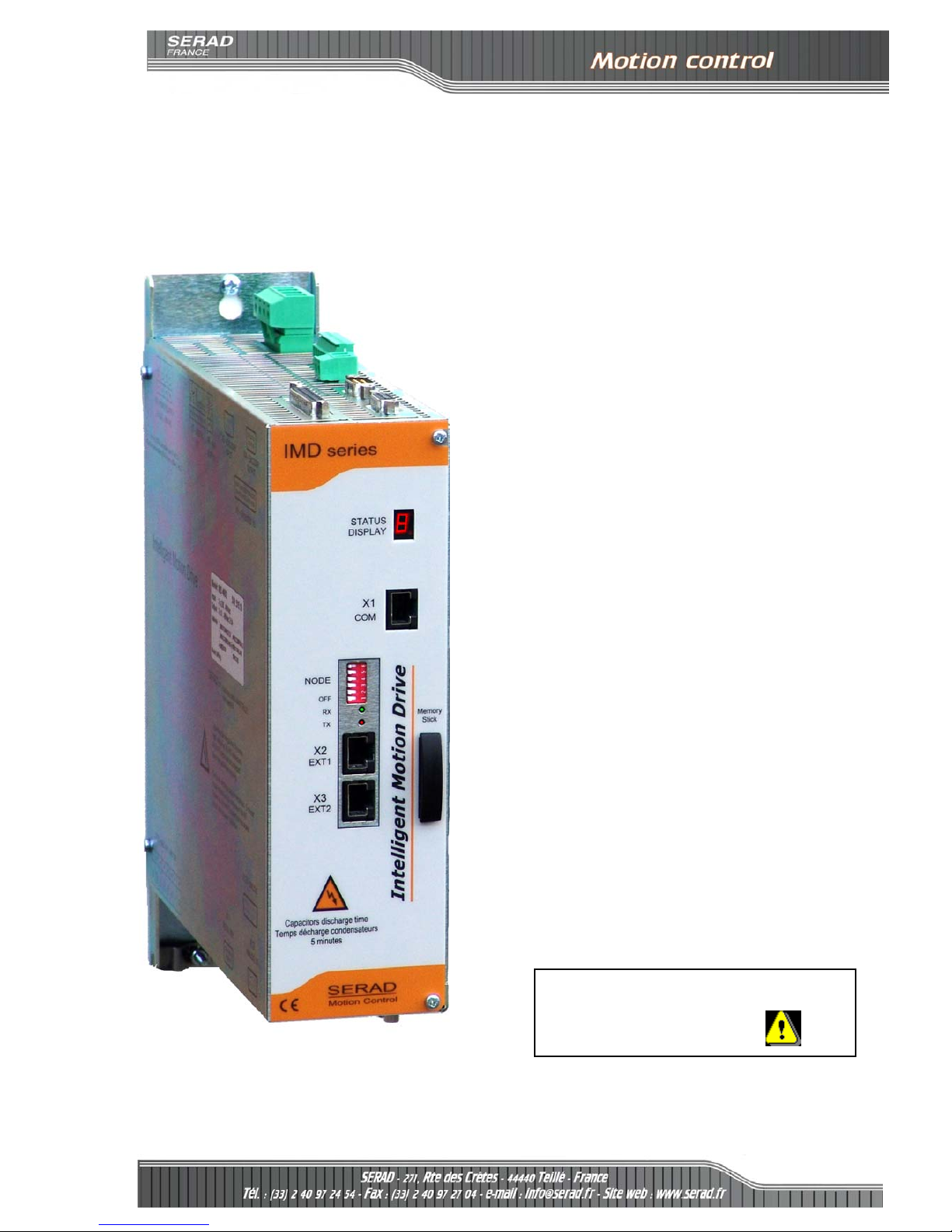
IMD Series
Read manual before installing and respect
all indications with this icon:
INSTALLATION
GUIDE


IMD Drive installation guide
R722 - 3 - SERAD S.A
Table of Contents
1- Introduction .................................................................................................. 4
1-1- Warning...................................................................................................... 4
1-2- MD series drive description....................................................................... 5
2- Installation .................................................................................................... 7
2-1- General....................................................................................................... 7
2-2- Front view .................................................................................................. 8
2-3- Top view ..................................................................................................... 9
2-4- Bottom view.............................................................................................. 10
2-5- Mounting .................................................................................................. 11
2-6- Connector pin assignments ...................................................................... 12
2-7- Cables....................................................................................................... 12
2-8- Connection diagrams / Protections ......................................................... 22
2-9- Stand-alone drive ..................................................................................... 22
2-10- Drive controlled by a motion controller ................................................ 24
2-11- Connecting a motor brake...................................................................... 25
2-12- System checks before starting ................................................................ 25
2-13- Error messages: ..................................................................................... 26
IMD Drive installation guide
R722 - 4 - SERAD S.A
1- Introduction
1-1- Warning
Read this manual before first installing, nonobservance may result in property
damages and in personal injuries.
Only suitable qualified personnel should undertake the mounting, installation,
operation and maintenance of the equipment must be complied with the general setup
and safety regulations for work on power installations (e.g. DIN, VDE, EN, IEC or
other national and international regulations).
It is important that all safety instructions are strictly followed. Personal injury can
result from a poor understanding of the safety requirements.
The following safety regulations should be followed:
•
VDE 0100
Specification for the installation of power systems
up to 1000 V
•
VDE 0113
Electrical equipment of machines
•
VDE 0160
Equipment for power systems containing electronic
components.
- Never open the equipment.
- Dangerous high voltages exist within the equipment and on the connectors.
Because of this, before removing any of the connectors, it is necessary to remove
the power and wait at least 5 minutes to allow the capacitors to discharge.
- Never connect or disconnect the drive with power applied.
- Some of the drive’s surfaces can be very hot.
Some of the drive's components are susceptible to damage from electrostatic
discharges. Always handle the equipment using appropriate anti-static precautions.
We have gone to great lengths to ensure this documentation is correct and complete. However, since it
is not possible to produce an absolutely error-free text. No responsibility will be assumed by SERAD
for all damages caused by using this documentation and software.
We reserve the right to make changes to all or part of the specification without prior notice.

IMD Drive installation guide
R722 - 5 - SERAD S.A
1-2- MD series drive description
Supply : 230V to 400V AC ±10% three phase or 230V AC ±10% single phase
Auxiliary supply : 24 V DC ±10%, 0.4A typical (0,7A max if all options)
Supply filter : Integral
Switching frequency : 6.67 kHz sine-wave PWM
DC bus voltage : 310V to 680V
Integral : 75 ohms 60W
Possibility to add an external resistor :
Min value Max. cont. power Imp power
Braking resistance :
60Ω 5KΩ 10KΩ
Short circuit between phases, phase to earth, over current, I2t
Over voltage, under voltage
Protection :
Motor feedback fault
Resolver
Motor feedback :
SinCos encoder Hiperface
(option)
Incremental encoger
Absolute encoder SSI
SinCos encoder Hiperface
(option)
Master encoder :
Virtual
Encoder emulation : Incremental : A, /A, B, /B, Z, /Z 1 to 100 000 points per rev
Diagnostic : STATUS display
RS 232 MODBUS RTU
IMDBUS : for master/slave application
CANopen
(option)
: DS 402, SDO, PDO, master or slave
PROFIBUS DP
* (option)
Communication :
SERCOS 16Mb
* (option)
4 inputs (with 2 fast inputs I3 and I4)
12 additional inputs with expansion module (with 2 fast inputs I15 and I16)
Type: PNP, 24V DC, 8mA per input and 15 per fast input
Logic 0: Between 0 and 5 V
Digital inputs :
Logic 1: Between 8 and 30 V
2 outputs as standard
S1 : Relay, 48V dc / 48V ac, 3A max
S2 : NPN (open collector) 24V dc, 100mA
8 additional outputs with expansion module
Type : PNP 24V dc, 500mA max per output
Digital outputs :
Protected against short circuit and over temperature.
2 inputs :
Input voltage : ±10 V
Maximum voltage : ±12 V
Input impedance : 20 Kohms
Analogue inputs :
Resolution : 16 bits for input 1 and 12 bits for input 2
1 output :
Output voltage : ±10 V
Maximum current : 5 mA
Analogue output :
Resolution : 8 bits
IMD Drive installation guide
R722 - 6 - SERAD S.A
Processor :150 MHz DSP and 100 000 gates FPGA
FLASH memory for programs and parameters
RAM memory for data
FRAM memory for variables
Architecture :
Real-time, multi-tasking kernel
Current loop : 75 µs
Speed loop : 150 µs
Control loops :
Position loop : 150µs
Torque mode
Speed mode
Position mode
Stepper Mode (pulse input, direction)
Motion functions (absolute, relative and infinite movements, S profile)
Operating modes :
Advanced motion functions (gearbox, CAM profiles, CAMBOX functions, triggered movement)
Operating temperature : 0 to 40°C
Storage temperature : -10 to 70°C
Degree of protection : IP 20
Weight 3,6 Kg
Drive Rated current Peak current ( 2s ) Rated power Dimensions w x h x d
IMD / 1 1,25 Aeff 2,5 Aeff 0,7 kVA 72 x 293 x 233
IMD / 2 2,5 Aeff 5 Aeff 1,4 kVA 72 x 293 x 233
IMD / 5 5 Aeff 10 Aeff 2,8 kVA 72 x 293 x 233
IMD / 10 10 Aeff 20 Aeff 5,6 kVA 72 x 293 x 233

IMD Drive installation guide
R722 - 7 - SERAD S.A
2- Installation
2-1- General
It is very important to adhere to the following:
A badly earthed connection can damage electronic drive components.
The drive must be installed vertically in free air to ensure cooling by natural
convection.
It must be protected from excess humidity, liquids, and dirt.
The motor, resolver and encoder cables must be screened, the screen being earthed
at both ends of the cable.
The analogue I/O must use screened cable, the screen being earthed at one end
only.
The cable for the RS 232 serial link between the drive and the PC must be screened,
the screen being earthed at both ends of the cable. It should be disconnected from the
drive when no longer in use. All of these cables, as well as the I/O cables, should be
run separately from the power cables.
Diodes must be fitted across the loads on all static digital outputs (Q2 to Q10).
These diodes must be positioned as close to the load as possible. The supply and
signal cables must be free from over-voltage transients.
Safety standards specify a manual reset after a stop caused either by a supply
interruption, or by an emergency stop or by a drive fault.
For all serious faults, it is obligatory to remove the high voltage supply to the drive.
The Drive Ready output should be connected in series in the emergency stop loop.
In the case of axis over-travel, the over-travel limit switches must be connected to
the limit inputs or in series with the emergency stop loop. It is also recommended to
use the software limits.
If the drive is configured in speed loop, the drive enable input should be controlled
by the supervisory controller (CNC, PLC etc).
If the drive is configured in position loop, the parameter "Maximum following
error" should be set appropriately.
If the drive contains an application program developed using iDPL, connect a
signal ‘Cabinet supplies OK’ to one of the digital inputs and monitor it in a nonblocking safety task. On detection of an excess following error the drive will be put in
open loop mode and the drive ready relay will be opened. If another action is required
you should use the SECURITY instruction.
IMD Drive installation guide
R722 - 8 - SERAD S.A
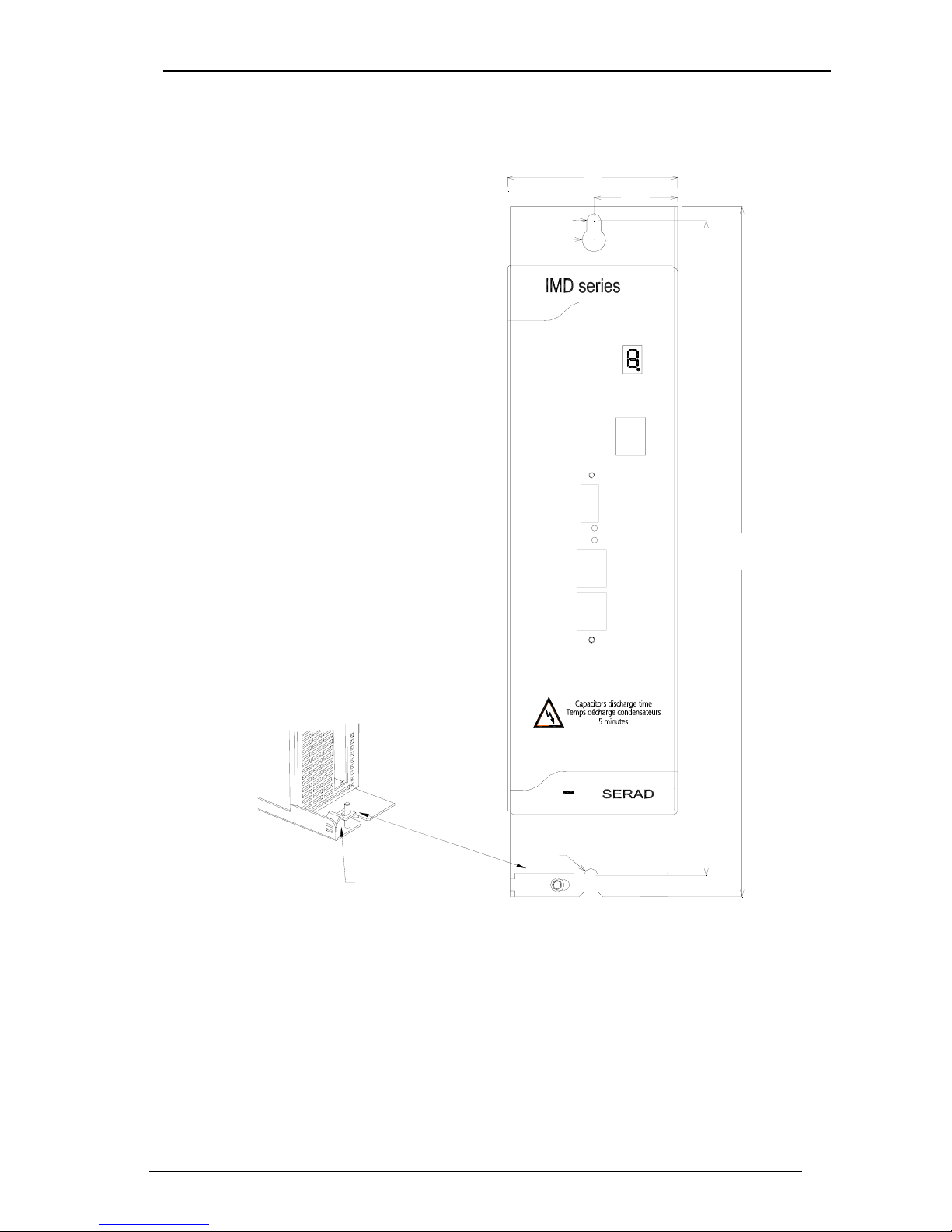
2-2- Front view
X1
COM
STATUS
X3
EXT2
X2
EXT1
NODE
CC
72
35.5
Ø
6
Ø
1
0
RX
TX
Ø6
2
7
8
.
5
Raccordement de la
tresse de blindage
du câble moteur
2
9
3
.
5
STATUS 7-segment diagnostic display
X1 COM RS-232 serial port for communication with a PC
X2 EXT1 Extension: Optional communications ports
X3 EXT2 Extension: Optional communications ports

IMD Drive installation guide
R722 - 9 - SERAD S.A
2-3- Top view
72
2
3
3
.
5
X
8
-
P
O
W
E
R
S
U
P
P
L
Y
3
X
2
3
0
.
.
.
.
.
4
8
0
V
A
C
X
7
-
D
I
G
I
T
A
L
I
/
O
X
6
-
A
U
X
.
S
U
P
P
L
Y
2
4
V
C
C
X
9
-
E
X
T
E
N
D
E
D
I
/
O
X
5
-
E
N
C
O
D
E
R
I
N
P
U
T
X
4
-
E
N
C
O
D
E
R
O
U
T
P
U
T
1
2
3
4
1
2
3
4
5
6
7
8
1
2
+
X4 ENCODER OUTPUT Multifunction encoder output
X5 ENCODER INPUT Multifunction encoder input
X6 24Vdc Auxiliary 24V DC supply
X7 I/O Digital I/O
X8 POWER SUPPLY Single / Three-phase power supply
X9 EXT I/O Option: I/O expansion board
The voltage on connector X8 can reach 480V!
 Loading...