

Sera iSTEP S 20,iSTEP S 30,iSTEP S 40,iSTEP S 50 Operating Instructions Manual
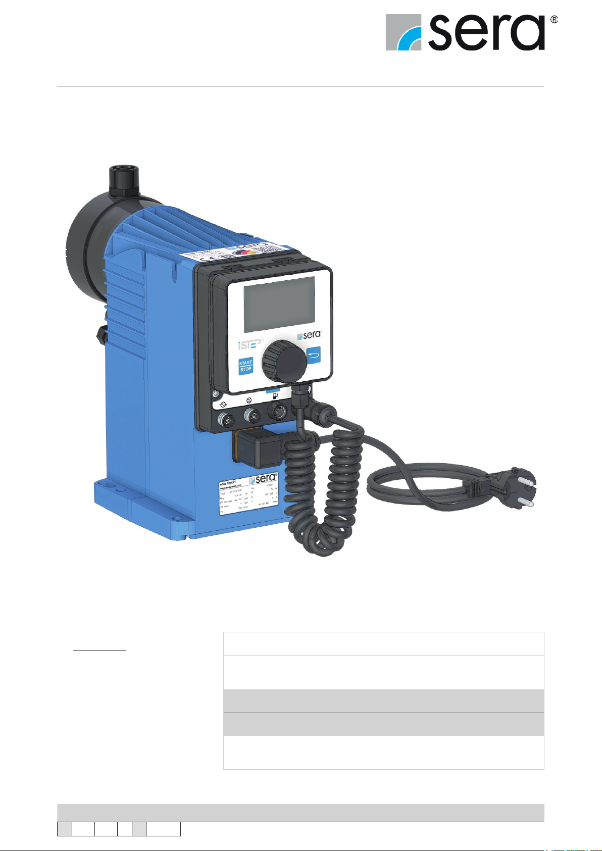
Stepper motor pump
®
iSTEP
Operating Instructions
iSTEP ®S 20
®
®
®
S 30
S 40
S 50
iSTEP
iSTEP
iSTEP
Manufacturer:
sera GmbH
sera-Straße 1
34376 Immenhausen
Germany
Tel.: +49 5673 999-00
Fax: +49 5673 999-01
info@sera-web.com
www.sera-web.com
Translation of the original operating instructions!
TA 508 Rev. 00 en 11/2015
Subject to technical modications!
Keep the operating manual for future use!
Record the exact type and serial number here.
(can be read off the type plate on the pump)
Type :
Serial No. :
These data are important in the case of queries or for ordering spare and/or wear
parts and must always be stated.
www.sera-web.com
1

Stepper motor pump
®
iSTEP
Operating Instructions
Content
1. General ....................................................................................................................................................... 4
1.1 General user information ...................................................................................................................... 4
1.2 Symbols and notes used in these operating instructions ..................................................................... 4
1.3 Notes attached to the product ..............................................................................................................4
1.4 Quality instructions ............................................................................................................................... 5
2. Safety instructions .................................................................................................................................... 5
2.1 Personnel qualication and training .....................................................................................................5
2.2 Dangers in case of inobservance of the safety instructions ................................................................. 5
2.3 Safety conscious working ..................................................................................................................... 5
2.4 Safety instructions for owner / operator ................................................................................................6
2.5 Safety instructions for maintenance, servicing and installation work ................................................... 6
2.6 Arbitrary modication and production of spare parts ............................................................................6
2.7 Improper operations .............................................................................................................................6
2.8 Intended use .........................................................................................................................................6
2.9 Operating conditions ............................................................................................................................7
2.10 Personal protection for maintenance and service .............................................................................. 7
2.11 Utilities/Lubricants ..............................................................................................................................7
2.12 Foreseeable misuse ........................................................................................................................... 8
2.12.1 Transport ....................................................................................................................................8
2.12.2 Assembly and installation ........................................................................................................... 8
2.12.3 Start-up ......................................................................................................................................8
2.12.4 Operation ...................................................................................................................................9
2.12.5 Maintenance/Repair ................................................................................................................... 9
2.12.6 Cleaning ..................................................................................................................................... 9
2.12.7 Shut-down ................................................................................................................................ 10
2.12.8 Disassembly ............................................................................................................................. 10
2.12.9 Disposal ...................................................................................................................................10
3. Transport and storage ............................................................................................................................ 11
3.1 General ............................................................................................................................................... 11
3.2 Storage ............................................................................................................................................... 11
4. Product description ................................................................................................................................12
4.1 Types ..................................................................................................................................................12
4.1.1 Type key ..................................................................................................................................... 12
4.1.2 Type plate ................................................................................................................................... 12
4.2 Materials ............................................................................................................................................. 13
4.3 Viscosity, pumped medium ................................................................................................................. 13
4.4 Noise measurement ...........................................................................................................................13
4.6 Delivery characteristic ........................................................................................................................14
4.6 Components of the diaphragm pump ................................................................................................. 15
4.7 Functional description ........................................................................................................................16
4.7.1 General ......................................................................................................................................16
4.7.2 Stroke mechanism with assembly pump .................................................................................... 16
4.7.3 Pump body ................................................................................................................................. 16
4.7.4 Suction / Pressure valve ............................................................................................................17
4.7.5 Diaphragm rupture monitoring device ....................................................................................... 17
4.7.6 Electronics with removable control element ............................................................................... 18
4.7.7 Automatic ventilation device (option) .......................................................................................... 19
4.7.8 Interface module (accessories) ................................................................................................. 19
4.7.9 Suction lances connection (accessories) ................................................................................... 19
5. Technical Data .........................................................................................................................................20
5.1 Output data .........................................................................................................................................20
5.3 Dimensions .........................................................................................................................................22
6. Assembly / Installation ............................................................................................................................24
7. Electrical connections ............................................................................................................................32
7.1 Mains power connection .....................................................................................................................32
7.2 Electrical interfaces ............................................................................................................................33
7.2.1 External control ..........................................................................................................................33
2
www.sera-web.com
Subject to technical modications!
TA 508 Rev. 00 en 11/2015

Stepper motor pump
®
iSTEP
Operating Instructions
7.2.2 Flow monitoring and ow rate measurement .............................................................................35
7.2.3 Level Connection .......................................................................................................................35
8. Operation in Ex-zone ..............................................................................................................................36
9. Start-up ..................................................................................................................................................... 36
10. Operation ...............................................................................................................................................37
10.1 Controls ............................................................................................................................................ 37
10.2 Navigation ........................................................................................................................................38
10.3 Start-up (initial commissioning) ........................................................................................................38
10.4 LED-Betriebsanzeigen .....................................................................................................................39
10.5 Menü ................................................................................................................................................40
10.6 Operating modes .............................................................................................................................. 42
10.6.1 MANUAL operating mode ........................................................................................................43
10.6.2 IMPULSE operating mode .......................................................................................................43
10.6.3 ANALOGUE operating mode ...................................................................................................45
10.6.4 BATCH operating mode ...........................................................................................................47
10.6.5 TIMER operating mode ............................................................................................................ 53
10.7 Settings (parameters) ....................................................................................................................... 54
10.8 Inputs/outputs ................................................................................................................................... 55
10.8.1 Input 1 (digital) .........................................................................................................................56
10.8.2 Inputs 2 and 3 (digital/analogue) .............................................................................................. 57
10.8.3 Outputs 1 and 2 (digital) ........................................................................................................... 58
10.8.4 Analogue output ......................................................................................................................59
10.9 Extras ...............................................................................................................................................59
10.9.1 Slow mode ...............................................................................................................................59
10.9.2 Speed limit ...............................................................................................................................60
10.9.3 Dosing monitor ......................................................................................................................... 60
10.9.4 Diaphragm monitor ................................................................................................................... 61
10.9.5 Level ......................................................................................................................................... 62
10.9.6 Venting .....................................................................................................................................63
10.10 SYSTEM .........................................................................................................................................65
10.10.1 Language ...............................................................................................................................65
10.10.2 Display ...................................................................................................................................65
10.10.3 SD Card .................................................................................................................................66
10.10.4 Time .......................................................................................................................................66
10.10.5 Password ...............................................................................................................................66
10.10.6 Maintenance ........................................................................................................................... 67
10.10.7 Data transfer ..........................................................................................................................68
10.10.8 Factory settings ...................................................................................................................... 68
10.11 Calibration of the delivery rate display ............................................................................................69
10.12 Info .................................................................................................................................................71
10.13 Messages ....................................................................................................................................... 71
11. Maintenance ........................................................................................................................................... 72
11.1 Overview of the tightening torques ................................................................................................... 73
11.2 Diaphragm replacement ...................................................................................................................74
12. Spare and wear parts ............................................................................................................................ 76
12.1 Wear parts ........................................................................................................................................ 76
12.2 Spare parts ....................................................................................................................................... 76
12.3 Spare and wear parts kit ..................................................................................................................77
13. Fault analysis and fault correction ...................................................................................................... 78
13.1 Analysis of the plain text error messages .........................................................................................78
13.2 Analysis of other faults .....................................................................................................................80
14. Shut-down .............................................................................................................................................. 82
15. Disposal .................................................................................................................................................82
15.1 Dismantling and transport ................................................................................................................82
15.2 Complete disposal ............................................................................................................................ 82
16. Certicate of non-objection .................................................................................................................. 83
TA 508 Rev. 00 en 11/2015
Subject to technical modications!
www.sera-web.com
3
Stepper motor pump
®
iSTEP
Operating Instructions
1. General
1.1 General user information
Before commissioning and during operation of the sera dosing pump the respective regulations valid at the place of
installation are to be observed.
The sera dosing pump is delivered ready for installation. Carefully read these instructions and especially the safety
instructions herein contained before installation and initial start-up of the pump.
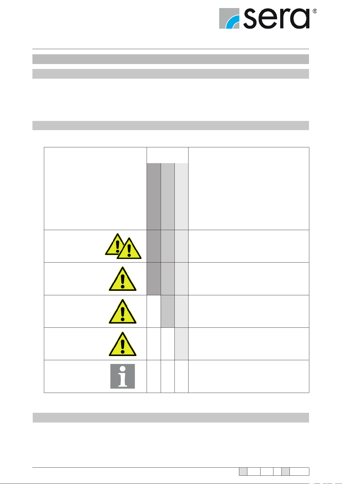
1.2 Symbols and notes used in these operating instructions
Special notes in these operating instructions are marked with text and danger symbols.
Designation of the note
(Text and symbol)
DANGER!
WARNING!
CAUTION!
Danger type
Danger of fatal injury
Risk of injury
Damage to property
Identies an imminent danger
X X X
X X X
X X
that results in fatal or severe injuries if not
avoided.
Designates a potentially dangerous situation
There might be danger to life or serious injury and
damage to property if it is not avoided.
Designates a potentially dangerous situation
There might be slight or minor injury or damage to
property if it is not avoided.
Denition of the note
(in the operating instructions)
Designates a potentially dangerous situation
that could lead to damage to property if not
ATTENTION!
NOTE!
X
avoided.
Designates information which helps to make work
easier and is useful for trouble-free operation.
1.3 Notes attached to the product
Symbols which are directly attached to the pump, e.g. arrows for direction of rotation or symbols for uid connections
are to be observed and kept in legible condition.
4
www.sera-web.com
Subject to technical modications!
TA 508 Rev. 00 en 11/2015
Stepper motor pump
®
iSTEP
Operating Instructions
1.4 Quality instructions
Observance of these operating instructions and, in particular, the safety instructions, helps to
■ avoid dangers to persons, machines and environment.
■ increase reliability and service life of the product and the complete system.
■ reduce repair cost and downtime.
The sera quality management and quality assurance system for pumps, systems, valves and ttings and
compressors is certied according to ISO 9001:2008.
The sera product meets the valid safety and accident prevention regulations.
Always keep these operating instructions within reach at the place of installation.
ATTENTION!
Pay attention to the safety data sheet of the medium! The owner must take corresponding accident prevention measures to protect operating personnel from
danger through the delivery media used!
DANGER!
2. Safety instructions
2.1 Personnel qualication and training
The personnel for operation, maintenance, inspection and installation must be suitably qualied for their tasks. The
owner must clearly dene responsibility and supervision of the personnel.
If the personnel do not have the knowledge required, then personnel is to be trained and instructed correspondingly.
Such training can be provided by the manufacturer / supplier upon order of the owner. In addition, the owner has to
ensure that personnel have understood the operating instructions completely.
2.2 Dangers in case of inobservance of the safety instructions
Inobservance of these safety instructions can result in danger to persons, hazards to the environment and damage
to the product.
Inobservance of the safety instructions may lead to:
■ Failure of important functions of the product/system.
■ Inobservance of prescribed methods for maintenance and servicing.
■ Danger to persons through electrical, mechanical and chemical inuences.
■ Hazards to the environment through leaking dangerous media.
2.3 Safety conscious working
The safety instructions specied in this operating manual, the national regulations for accident prevention, the safety
regulations for the pumped medium valid at the place of installation as well as internal working-, operating-, and safety
instructions of the owner are to be observed.
TA 508 Rev. 00 en 11/2015
Subject to technical modications!
www.sera-web.com
5
Stepper motor pump
®
iSTEP
Operating Instructions
2.4 Safety instructions for owner / operator
Leaking hazardous delivery media and operating supplies are to be disposed off in such a way that any danger to
persons and the environment is excluded. The legal regulations are to be observed.
Danger caused by electrical energy is to be avoided.
2.5 Safety instructions for maintenance, servicing and installation work
The owner must ensure that all maintenance, inspection and installation work is exclusively carried out by authorised
and qualied skilled personnel who have sufciently informed themselves by in-depth study of the operating manual.
Only use spare parts which comply with the requirements of the specied operating conditions.
All screw and other connections may only be removed when the system is not
under pressure.
DANGER!
Arrange replacement of defective mains power connection cables and signal cables by specialist personnel.
DANGER!
2.6 Arbitrary modication and production of spare parts
Modications of or changements to the pump are only permitted after previous agreement of the manufacturer. Original spare parts and accessories which were approved by the manufacturer are essential for safety reasons.
If the pumps (e.g. drive motor) are modied without au-thorization of the manufacturer or spare parts are used which are not approved, any warranty claim becomes
null and void.
CAUTION!
2.7 Improper operations
Operating safety of the supplied product is only guaranteed if the product is used as intended, according to the
descriptions in Chapter 2.8 of these operating instructions.
2.8 Intended use
The sera product is only to be deployed according to the intended purpose stated in the product description and the
acceptance test certicate.
If the product is to be used for other applications, then the suitability of the product for the new operating conditions
must be discussed with sera beforehand!
Criteria for operation in accordance with the intended use:
■ Observe characteristics of the medium (please see safety- and product data sheet of the delivery
medium – the safety data sheet is to be provided by the supplier / owner of the medium).
■ Resistance of the materials which come into contact with the medium.
■ Operating conditions at the place of installation.
■ Pressure and temperature of the medium.
■ Voltage supply.
6
www.sera-web.com
Subject to technical modications!
TA 508 Rev. 00 en 11/2015

Stepper motor pump
®
iSTEP
Operating Instructions
Check stability of the materials which come into contact with the pumped medium!
DANGER!
2.9 Operating conditions
■ Ambient temperature: ► 0°C to 40°C
■ Climate ► relative air humidity < 90%
■ Installation altitude ► max 2000m above sea level
■ Pump design data for dosing and its temperature can be found in the order conrmation.
■ EMI ► 3m minimum distance of emitters with an electromagnetic eld strength of >5V/m and a frequency band
of 380-585 MHz.
The pump is exclusively intended for the designed operating conditions in the
operating manual and order conrmation!
DANGER!
2.10 Personal protection for maintenance and service
The provisions of the German Ordinance on Hazardous Substances (GefStoffV) (§14 Safety Data Shee) and relevant
national safety regulations for the pumped medium must strictly be adhered to.
In case of accidents check whether the following substances are emitted:
■ Leaking uids.
■ Leaking vapours.
■ Noise emissions (sound level).
Emissions are to be monitored by corresponding controly systems of the total installation.
Wear protective clothing, gloves and suitable face protection and respirator according to the safety data sheet for the pumped medium!
DANGER!
Personal protective equipment must be provided by the owner!
NOTE!
NOTE!
2.11 Utilities/Lubricants
The sera stepper motor pump is lubricated for life.
TA 508 Rev. 00 en 11/2015
Subject to technical modications!
www.sera-web.com
7
Stepper motor pump
®
iSTEP
Operating Instructions
2.12 Foreseeable misuse
The following misuse is assigned to the life cycles of the machine.
Misuse can result in danger to the operating personnel!
DANGER!
2.12.1 Transport
■ Tipping behavior during transport, loading and unloading ignored.
■ Weight for lifting underestimated.
2.12.2 Assembly and installation
■ Power supply not fuse protected (no fuse/fuse too large, power supply not conforming to standards).
■ No or improper fastening material of the pump.
■ Improper connection of the pressure pipes, wrong material i.e. PTFE tape and unsuitable connection pieces.
■ Liquid pipes confused.
■ Threads overturned/damaged.
■ Pipes bent during connection in order to compensate for alignment errors.
■ Supply voltage connected without earthed conductor.
■ Socket for safe disconnection of the power supply difcult to reach.
■ Wrong connecting cables for supply voltage (cross-section too small, wrong insulation).
■ Parts damaged (e.g. vent valve, ow meter broken off).
■ Wrongly dimensioned pressure and suction pipe.
■ Incorrect dimensioned and improperly fastened pump panel (panel broken off).
■ Short circuit of the internal power supply (24 V DC) at the control cable during installation.
■ Admissible current load of the digital outputs exceeded.
■ No sera sensors for ow rate / ow or ll level ► damage to the electronics.
■ Electronics opened in order to connect the mains cable directly to the power supply ► electric shock or dam-
age to the electronics.
■ Connection of incorrect mains voltage or mains frequency ► destruction of electronics or automatic venting
device.
■ The pumped medium is conveyed into the environment in the case of pumps with automatic or manual vent
valve if the return pipe was improperly tted or not tted at all. ► Danger for the operator.
■ Connection of the cubic connector (mains connection) without seal.
■ Removal of protective caps of unused connections.
■ Non-observance of the ambient conditions (temperature, indoors or weather-protected placement).
2.12.3 Start-up
■ Cover on vent openings (e.g. motor).
■ Suction or pressure pipes closed (i.e. foreign matters, particle size, stop valves).
■ Start-up with damaged system.
■ Removal of protective caps of unused connections during the commissioning.
■ Incorrect control of the pump or incorrect control signals ► sudden start-up.
■ Incorrect parametrisation of the pump ► inadvertent start-up.
■ Distance between dosing pump and other dosing pumps or other electrical consumers insufcient ► faults
due to electromagnetic radiation.
■ Control cable too long > 30 m ► malfunctions due to EMC.
■ Control cable and power cable run parallel to each other ► malfunctions due to EMC.
■ Operation without connected return pipe of the vent valve.
8
www.sera-web.com
Subject to technical modications!
TA 508 Rev. 00 en 11/2015
Stepper motor pump
®
iSTEP
Operating Instructions
2.12.4 Operation
■ Fault message ignored ► faulty dosing / process error.
■ Pipes hit, pulsation damper not used ► damage to the pipes, medium is leaking.
■ Pumped medium contains particles or is contaminated.
■ External fuse bridged ► no cut off in case of an error.
■ Ground wire removed ► no cut off by fuse in case of an error, supply voltage directly at the housing.
■ Insufcient lighting of the working place.
■ Suction height too high, pump capacity too low ► process error.
■ Arbitrary modication of the pump (valves, internal fuse, …).
■ Wearing of unsuitable protective clothing / no protective clothing at all.
■ Use or operation of the pump with damaged electrical supply / control cable.
■ No check of diaphragm rupture due to removal of the MBE.
■ Non-observance of the compatibility of pump components with the pumped media used. The pump is exclu-
sively intended for the pumped media stated in the order conrmation.
■ No free return of the venting valve (option) or venting valve not connected.
2.12.5 Maintenance/Repair
■ Carrying out work that is not described in the operating manual (work on the drive housing and hand-held
control unit).
■ Disregard of the maintenance intervals specied in the operating manual.
■ Use of incorrect spare parts/oils (e.g. not sera original spare parts, wear parts, wrong viscosity).
■ Improper mounting of spare and wear parts (e.g. incorrect tightening torque for pump body).
■ Oil level not checked.
■ Use of cables with damaged insulation.
■ No shutdown / no protection against a restart before maintenance work.
■ Insufcient removal of the pumped medium before the replacement of spare and wear parts.
■ Restart without sufcient fastening.
■ Valves mixed up.
■ Mix-up of sensor cables.
■ Pipes not connected (e.g. suction and pressure pipes, vapour recovery pipes).
■ Seals damaged ► medium leaks.
■ Seals not installed ► medium leaks.
■ Wearing of unsuitable protective clothing / no protective clothing at all.
■ Operation of an uncleaned system.
■ Pumped medium contaminated with oil.
■ Poorly ventilated room.
■ Removal of protective caps during the maintenance.
■ Ingress of pumped medium or soiling in built-in pump, drive housing and pump body.
2.12.6 Cleaning
■ Wrong rinsing medium (material changed, reaction with the medium).
■ Wrong cleaning agent (material changed, reaction with the medium).
■ Cleaning agent remains in the system (material changed, reaction with the medium).
■ Protective clothing insufcient or missing.
■ Use of unsuitable cleaning utensils (material changed, mechanical damage by high pressure cleaner).
■ Untrained personnel.
■ Vent openings clogged.
■ Parts torn off.
■ Sensors damaged.
■ Non-observance of the safety data sheet.
■ Control elements actuated.
■ Poorly ventilated room.
TA 508 Rev. 00 en 11/2015
Subject to technical modications!
www.sera-web.com
9

Stepper motor pump
®
iSTEP
Operating Instructions
2.12.7 Shut-down
■ Pumped medium not completely removed.
■ Disassembly of pipes with the pump running/with residual pressure.
■ Disconnection of the electrical connections in a wrong sequence (ground wire rst).
■ Disconnection from the power supply not ensured ► danger through electricity.
■ Poorly ventilated room.
■ Falsche oder keine Schutzkleidung.
2.12.8 Disassembly
■ Residues of the pumped medium and utilities in the system.
■ Use of wrong disassembly tools.
■ Wrong or no protective clothing at all.
■ Poorly ventilated room.
2.12.9 Disposal
■ Improper disposal of the pumped medium, utilities and materials.
■ No marking of hazardous media.
■ Falsche Entsorgung der Elektronik.
10
www.sera-web.com
Subject to technical modications!
TA 508 Rev. 00 en 11/2015
Stepper motor pump
®
iSTEP
Operating Instructions
3. Transport and storage
3.1 General
sera products are checked for perfect condition and function previous to shipment.
Check for transport damage immediately after arrival of goods. If damage is found, this is to be reported immediately
to the responsible carrier and the manufacturer.
The packaging material must be disposed of appropriately!
NOTE!
3.2 Storage
An undamaged packaging protects the unit during storage and should only be opened when the product is installed.
Proper storage increases the service life of the product and includes prevention of negative inuences such as heat,
moisture, dust, chemicals etc.
The following storage specications are to be obsered:
■ Storage place: cool, dry, dustfree and slightly ventilated
■ Storage temperature between 0°C and +40°C
■ Relative air humidity not more than 50 %.
■ The maximum storage time for the standard system is 12 months.
If these values are exceeded, metal products should be sealed in foil and protected from condensation water with a
suitable desiccant.
Do not store solvents, fuels, lubricants, chemicals, acids, disinfectants and similar in the storage room.
TA 508 Rev. 00 en 11/2015
Subject to technical modications!
www.sera-web.com
11
Stepper motor pump
®
iSTEP
Operating Instructions
4. Product description
4.1 Types
4.1.1 Type key
Type of drive
Series
(litre/hour)
1 2 3
iSTEP S 20
max. nominal capacity
(example)
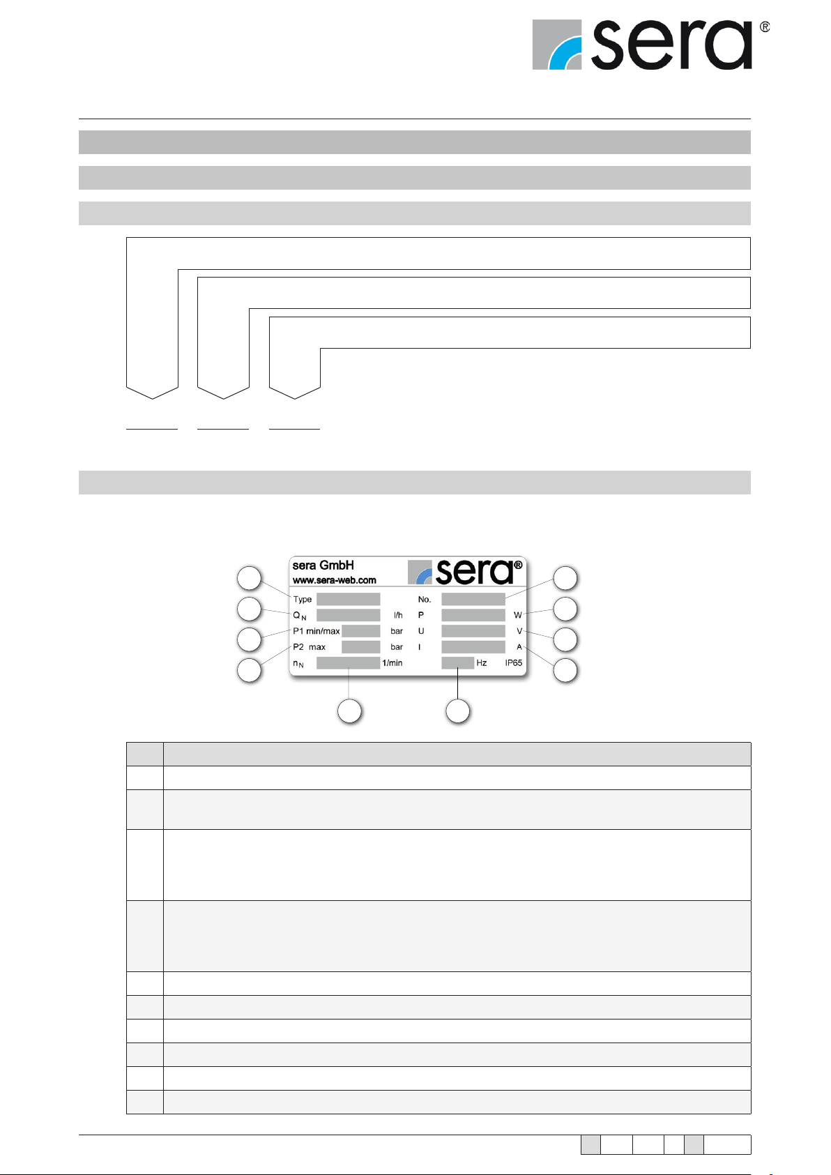
4.1.2 Type plate
Each sera dosing pump is factory provided with a type plate.
The following information can be found on this type plate.
1
2
3
4
5 6
7
8
9
10
12
No. Designation
1 Pump type
Nominal ow rate
2
Delivery volume of the pump at rated pressure with media similar to water.
Minimum/maximum permissible pressure in the pump inlet
Minimum/maximum permissible pressure in the inlet cross section which the pump can be used for.
3
Please consider that pressure depends on rotation speed, ow rate, temperature and static pressure
at the inlet.
Maximum permissible pressure in the pump outlet
Maximum permissible pressure in the outlet cross section which the pump can be used for. Please
4
consider that pressure depends on rotation speed, ow rate, temperature and static pressure at the
outlet.
5 Nominal stroke frequency
6 Rated frequency
7 Serial number of the pump
8 Max. power consumption
9 Max. operating voltage
10 Max. current consumption
www.sera-web.com
Subject to technical modications!
TA 508 Rev. 00 en 11/2015

Stepper motor pump
®
iSTEP
Operating Instructions
4.2 Materials
The materials used are stated in the order conrmation and the product description.
4.3 Viscosity, pumped medium
The diaphragm pump is suitable for uids with viscosities < 100 mPas.
Medium state ► from 50 l/h, max. 5% solids, grain size 30 µm.
4.4 Noise measurement
According to DIN 45635 the measured sound pressure level of the diaphragm pumps is below 70 dB (A).
TA 508 Rev. 00 en 11/2015
Subject to technical modications!
www.sera-web.com
13
Stepper motor pump
®
iSTEP
Operating Instructions
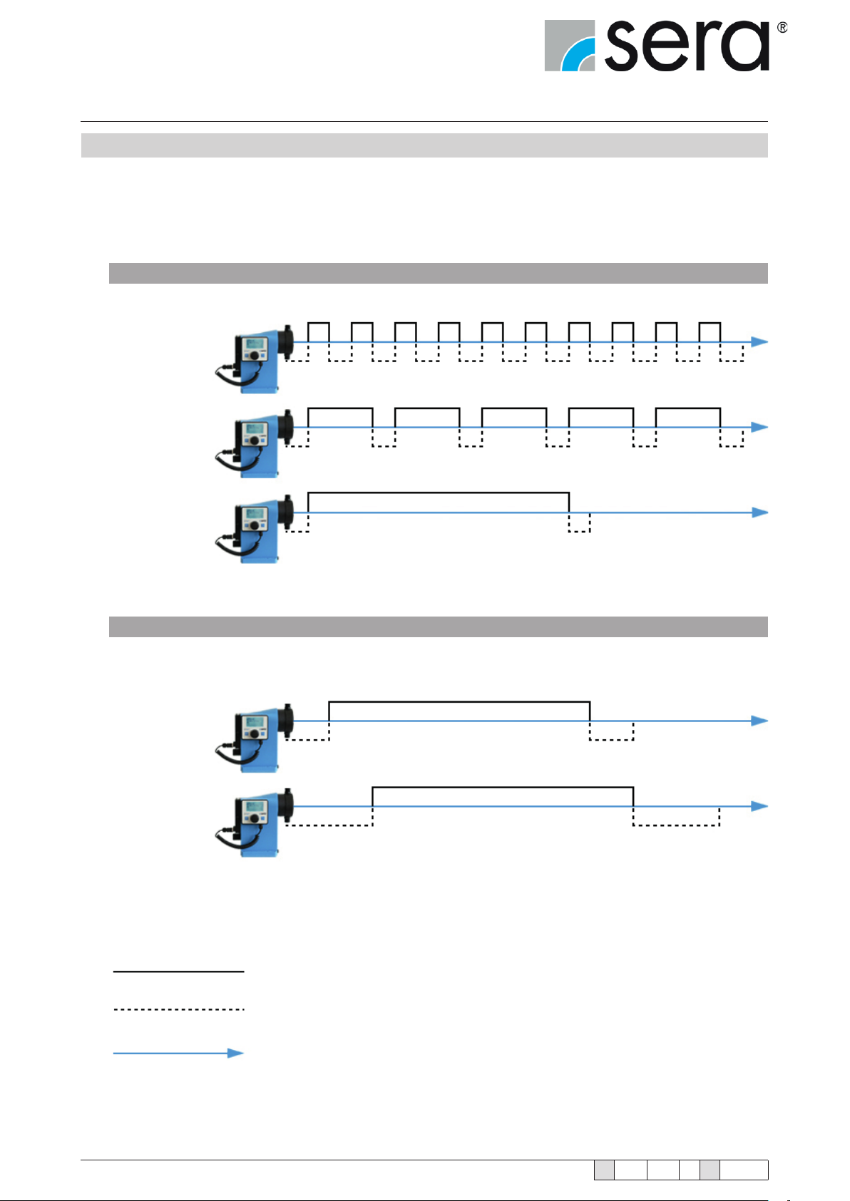
4.6 Delivery characteristic
The stepped motor pump iSTEP
For low delivery volumes, the pump runs the suction stroke at maximum speed and adjusts the speed of the pressure
stroke to the desired delivery volume. A constant ow rate is achieved that enables gentle dosing with low pulsation.
Standard Operation
100%
Flow rate
50%
Flow rate
®
can perform the pressure and suction strokes at different speeds.
10%
Flow rate
Slow Mode for viscous media
20%
Flow rate
15%
Flow rate
14
Pressure stroke
Suction stroke
Time
www.sera-web.com
Subject to technical modications!
TA 508 Rev. 00 en 11/2015
Stepper motor pump
®
iSTEP
Operating Instructions
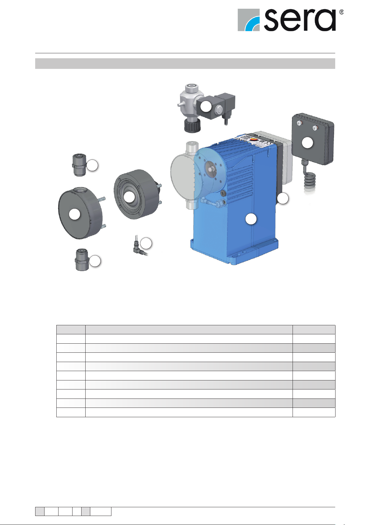
4.6 Components of the diaphragm pump
1
9
8
4
2
6
7
5
3
No. Designation Remark
1 Pressure valve
2 Pump body
3 Suction valve
4 Assembly pump
5 Diaphragm rupture monitoring device
6 Stroke mechanism
7 Electronic
8 Operating panel with graphic display
9 Automatic ventilation device
option
TA 508 Rev. 00 en 11/2015
Subject to technical modications!
www.sera-web.com
15
Stepper motor pump
®
iSTEP
Operating Instructions
4.7 Functional description
4.7.1 General
sera dosing pumps are run-dry safe oscillating displacement pumps that are characterised by high tightness of the
dosing head. The uid is conveyed by a deformable diaphragm.
The stepper motor pumps consist of the following (main) components:
■ Drive housing
■ Assembly pump
■ Pump body
■ Suction and pressure valve
■ Electronics with control panel
■ Diaphragm rupture monitoring device
4.7.2 Stroke mechanism with assembly pump
The stroke mechanism of the sera stepped motor pump
consists of a straight slider crank mechanism that converts
the rotary movement of the stepped motor into a linear
movement.
The control of the stepped motor is performed by the
electronics integrated in the stroke mechanism.
The pumped medium (1) is conveyed by an elastic drive
diaphragm (2). The stroke movement of the drive diaphragm
is transferred to the pumped medium by the oscillating
eccentric and the push rod. This results in the suction and
pressure stroke.
4.7.3 Pump body
Depending on the applied backpressure, movements of the plastic pump body in elastic materials are possible.
This does not affect the pumps’s service life or operational reliability.
2
1
16
www.sera-web.com
Subject to technical modications!
TA 508 Rev. 00 en 11/2015
Stepper motor pump
®
iSTEP
Operating Instructions
4.7.4 Suction / Pressure valve
The pump valves are ball valves that only work properly in a
vertical position. The condition of the valves has a deciding effect on the operating capability of the pump.
Valves must be exchanged as complete units.
When replacing the valves it is important to check the ow direction (1).
Pressure valve above; Suction
valve below!
ATTENTION!
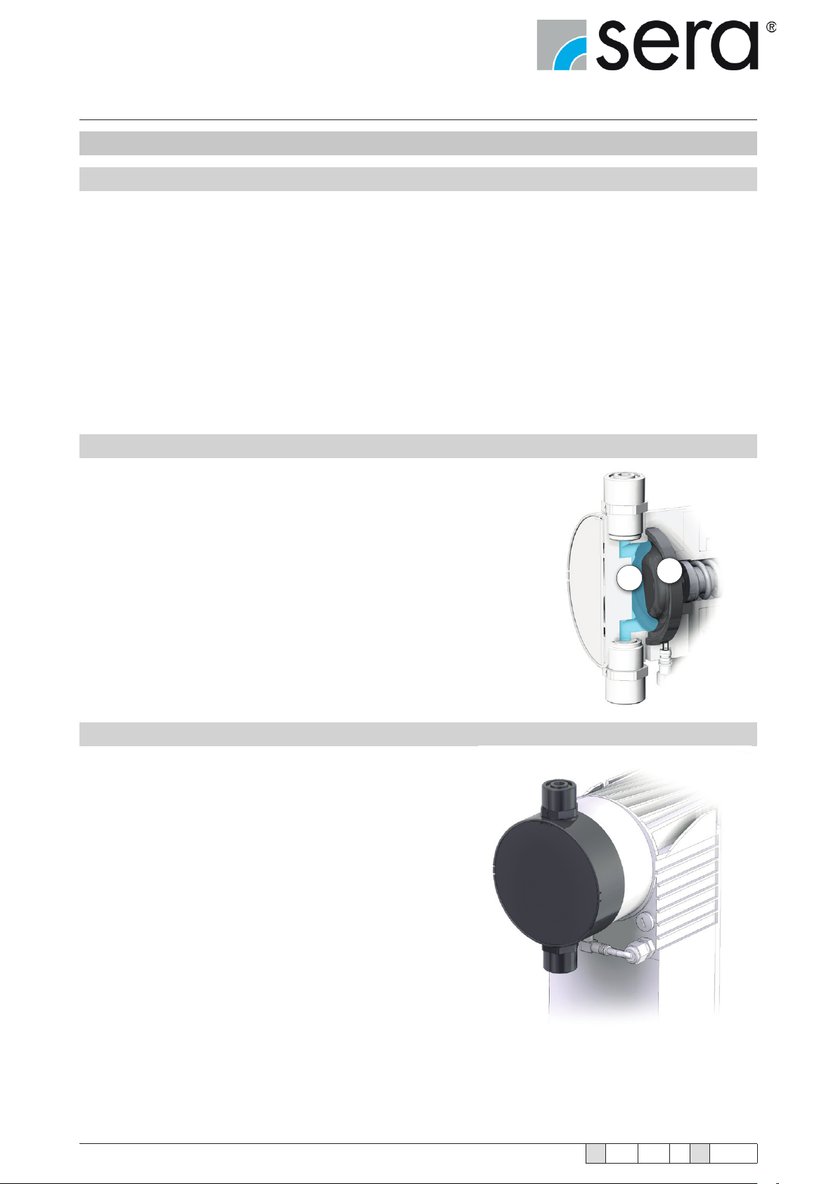
4.7.5 Diaphragm rupture monitoring device
iSTEP® stepped motor pumps are equipped with a conductive
diaphragm monitoring device.
The sensitivity of the diaphragm
rupture monitoring device can
be adapted to the conductivity of
the medium via the electronics.
ATTENTION!
The diaphragm monitoring device MBE-02 (1) is mounted in the
base ring (2) and permanently connected to the electronics in
the drive housing (3).
Factory setting 50%, approx. 10
µS/cm.
1
1
2
3
TA 508 Rev. 00 en 11/2015
Subject to technical modications!
1
www.sera-web.com
17
Stepper motor pump
®
iSTEP
Operating Instructions
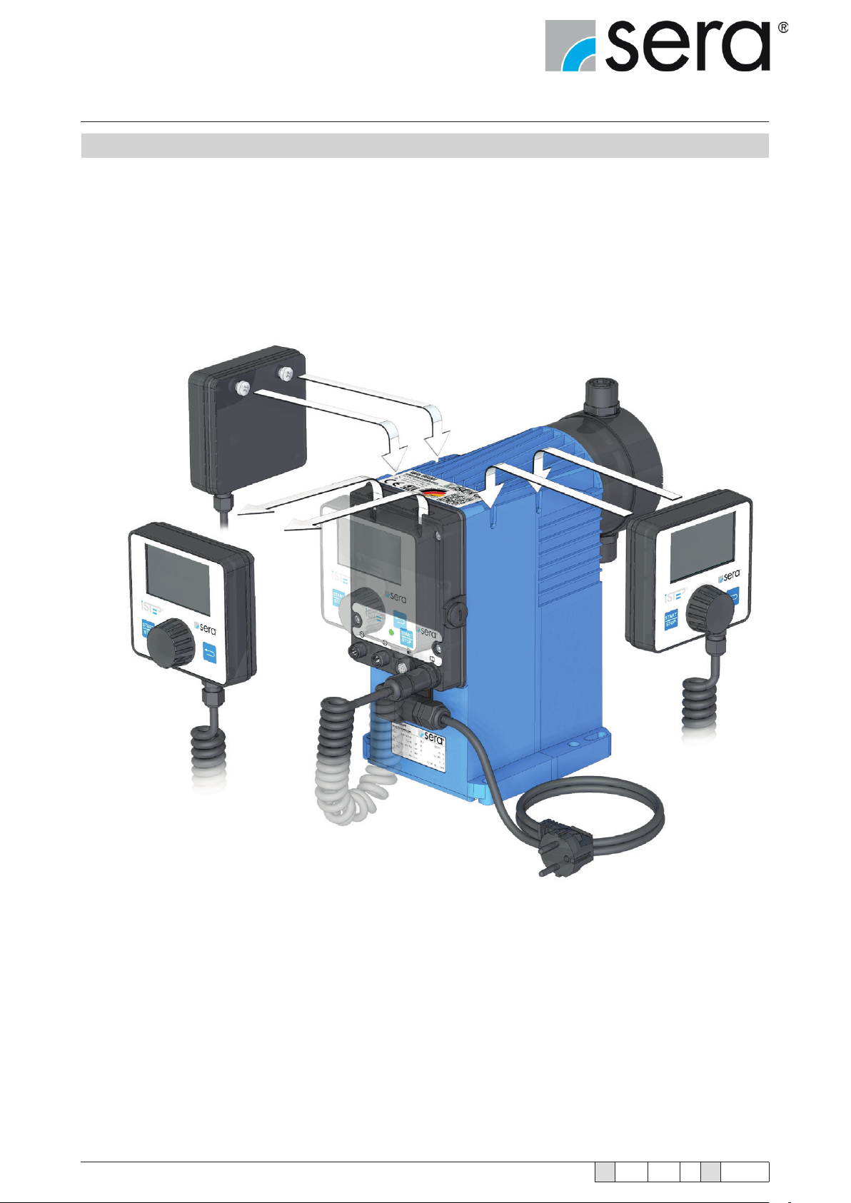
4.7.6 Electronics with removable control element
Among other things, the electronics enable the proportional dosing via analogue signals 4 … 20 mA or contact
signals with the possibility of pulse division or pulse multiplication.
The graphical display shows information about the current status of the dosing pump.
A connection for ow monitoring or ow rate measurement and an "empty" signal with pre-alarm and dry run alarm
are available as standard.
The removable control element with graphical display can be attached to the corresponding side on the housing
depending on the operating side.
18
www.sera-web.com
Subject to technical modications!
TA 508 Rev. 00 en 11/2015
Stepper motor pump
®
iSTEP
Operating Instructions
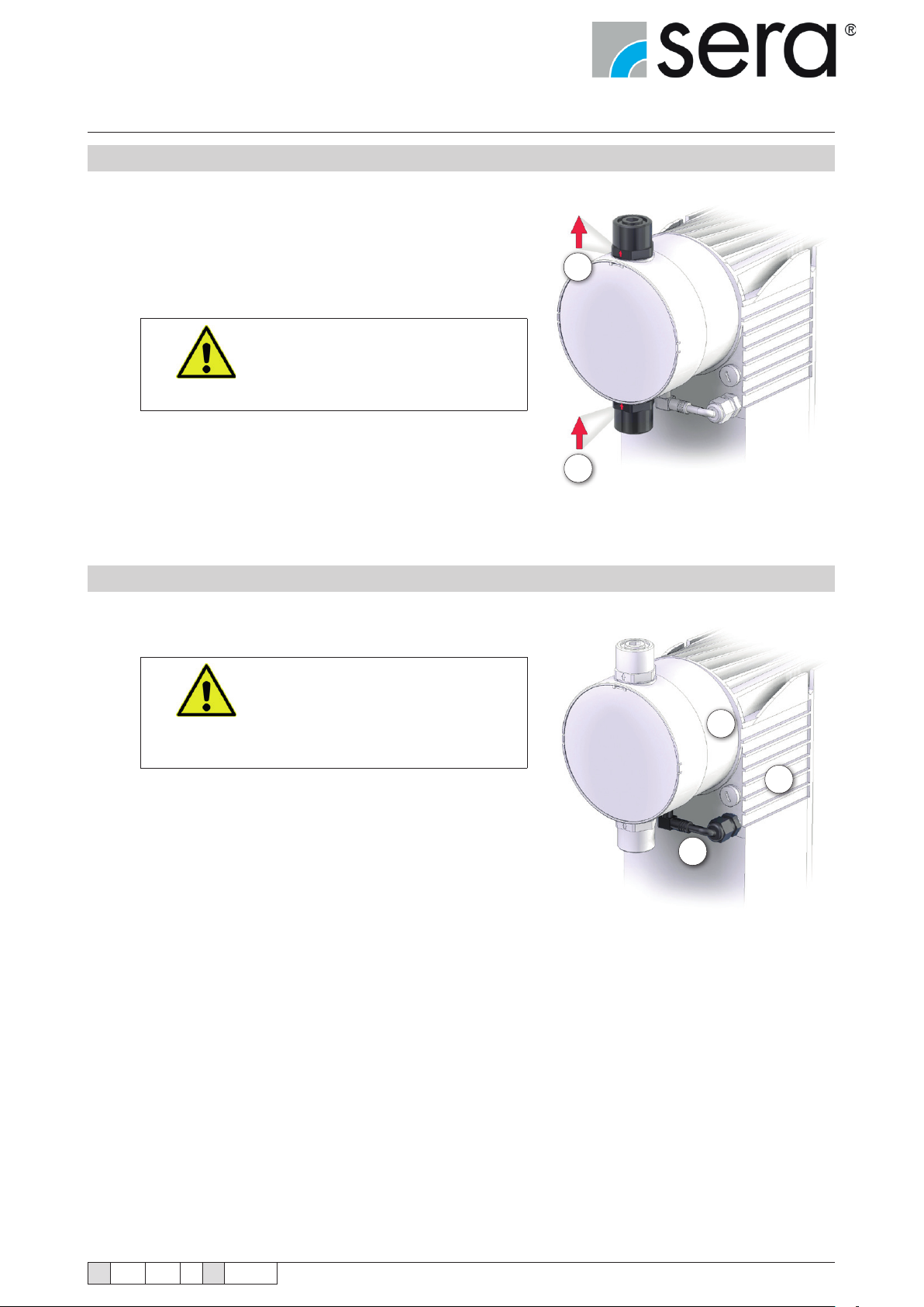
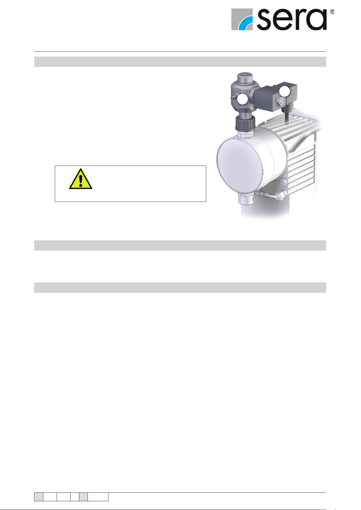
4.7.7 Automatic ventilation device (option)
An automatic ventilation device attached to the pressure port
can optionally be used for the stepped motor pumps.
The stepped motor pump vents the dosing head of the pump
and the suction line either using an external signal or manually
controlled and/or automatically at set intervals. The automatic
ventilation device consists of a combination of a check valve (1)
that should prevent the ow back of liquids and a solenoid valve
(2). When the controlled solenoid valve opens, the spring-loaded armature with attached seal is lifted from the valve seat and
pressure is relieved from the space between the pump valve
and the integrated check valve. Thus the pump and the pipe on
the suction side can be vented without pressure.
ATTENTION!
2
1
Always install the pump above
the suction container and mount
the return pipe with descending
gradient to the suction container.
4.7.8 Interface module (accessories)
The interface module provides level input and Probus or Pronet connectivity.
4.7.9 Suction lances connection (accessories)
In order to connect the stepped motor pump to a sera suction lance, an 8-pole cable connector with M12 thread
is needed (accessory part number: 90042494 or 90022885).
This cable connector is connected to the level input of the iSTEP
See chapter 7.2.3 "Level Connection" for pin assignment.
®
.
TA 508 Rev. 00 en 11/2015
Subject to technical modications!
www.sera-web.com
19
Stepper motor pump
®
iSTEP
Operating Instructions
5. Technical Data
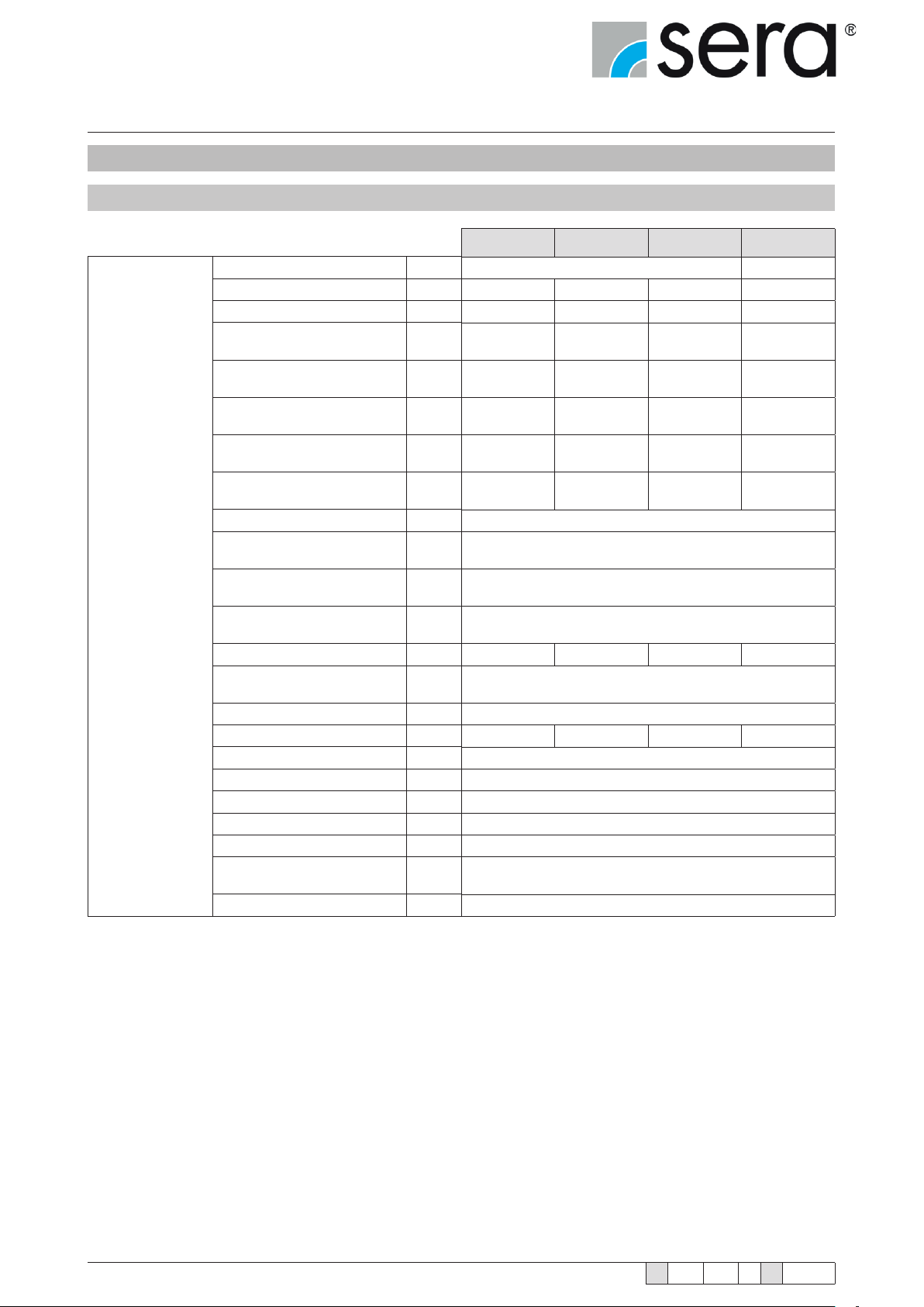
5.1 Output data
Mechanical data
Setting range
Max. dosing capacity [l/h]
Min. dosing capacity [l/h]
Max. dosing capacity
Slow Mode 25%
Max. dosing capacity
Slow Mode 50%
Max. dosing capacity
Slow Mode 75%
Stroke volume
Max. permissible pressure
at outlet of pump (P
Accuracy of repeatability [%]
Min. permissible pressure
at inlet of pump
Max. permissible pressure
at inlet of pump
Max. suction height
(with liquids similar to water)
Nominal diameter [DN]
Max. viscosity without
spring-loaded valves
Connecting thread
Nominal frequency [1/min]
Stroke length [mm]
Max. liquid temperature [°C]
Min. liquid temperature [°C]
Max. operating temperature [°C]
Min. operating temperature [°C]
max)
2
[l/h]
[l/h]
[l/h]
[ml/
Stroke]
[bar]
[bar]
[bar]
[m WS]
[mPas]
(=cP)
®
iSTEP
S 20 iSTEP
20 30 40 50
0,02 0,03 0,04 0,05
17,3 25,8 34,3 43,4
13,5 20,1 26,6 34,0
8,3 12,0 16,0 20,6
1,75 3,33 3,51 4,39
10 7 6 3
5 5 5 8
190 150 190 190
®
S 30 iSTEP
1:1000
± 5%
-0,3
0,5
3
100
G3/4
3,5
60
10
40
0
®
S 40 iSTEP
®
S 50
20
Max. storage temperature [°C]
Min. storage temperature [°C]
www.sera-web.com
Subject to technical modications!
40
0
TA 508 Rev. 00 en 11/2015
Stepper motor pump
®
iSTEP
Operating Instructions
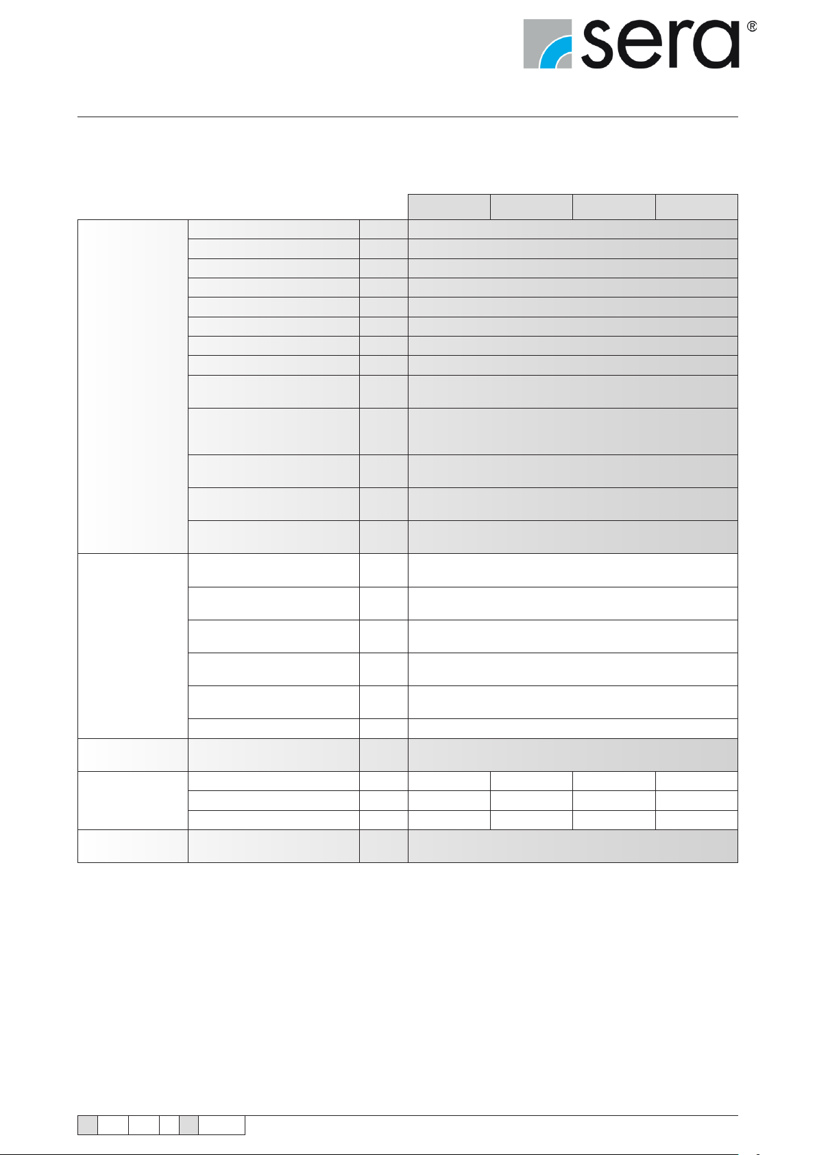
Elektrical data
Signal input
Signal output
Weight
Dimension
Sound pressure
Max. power consumption [W]
Voltage [V]
Frequency [Hz]
Max. inrush current (100V) [A]
Max. inrush current (230V) [A]
Electrical safety class
Enclosure class
Length of mains cable [m]
Input Voltage / Control input [V DC]
Min. pulse length [ms]
Recommended fuse
230V min.
Recommended fuse
110V min.
Recommended fuse
acc. to UL489/UL1077
Max. load
Contact input
Max. load for
External stop input
Impedance at 0/4-20 mA
analog input
Max. resistance in
level input
Max. resistance in
pulse circuit
[Ω]
[Ω]
[Ω]
Sampling rate [ms]
Impedance at 0/4-20 mA
analog output
[Ω]
Plastic [kg]
Steel [kg]
Diaphragm diameter [mm]
Max. sound pressure
at max. burden
[dB(A)]
iSTEP
®
S 20 iSTEP
®
S 30 iSTEP
®
S 40 iSTEP
75
100 – 240 AC
50/60
2
1,2
II
IP65
2
24
55
C10A circuit breaker
C10A circuit breaker
C10A
24V / 10 mA
24V / 10 mA
47
4K
100K
1
120
6,1 6,1 6,1 6,3
7 7 7 7,2
44 64 64 78
LP(A)<65dB(A) +/-5dB(A)
®
S 50
TA 508 Rev. 00 en 11/2015
Subject to technical modications!
www.sera-web.com
21
Stepper motor pump
®
iSTEP
Operating Instructions
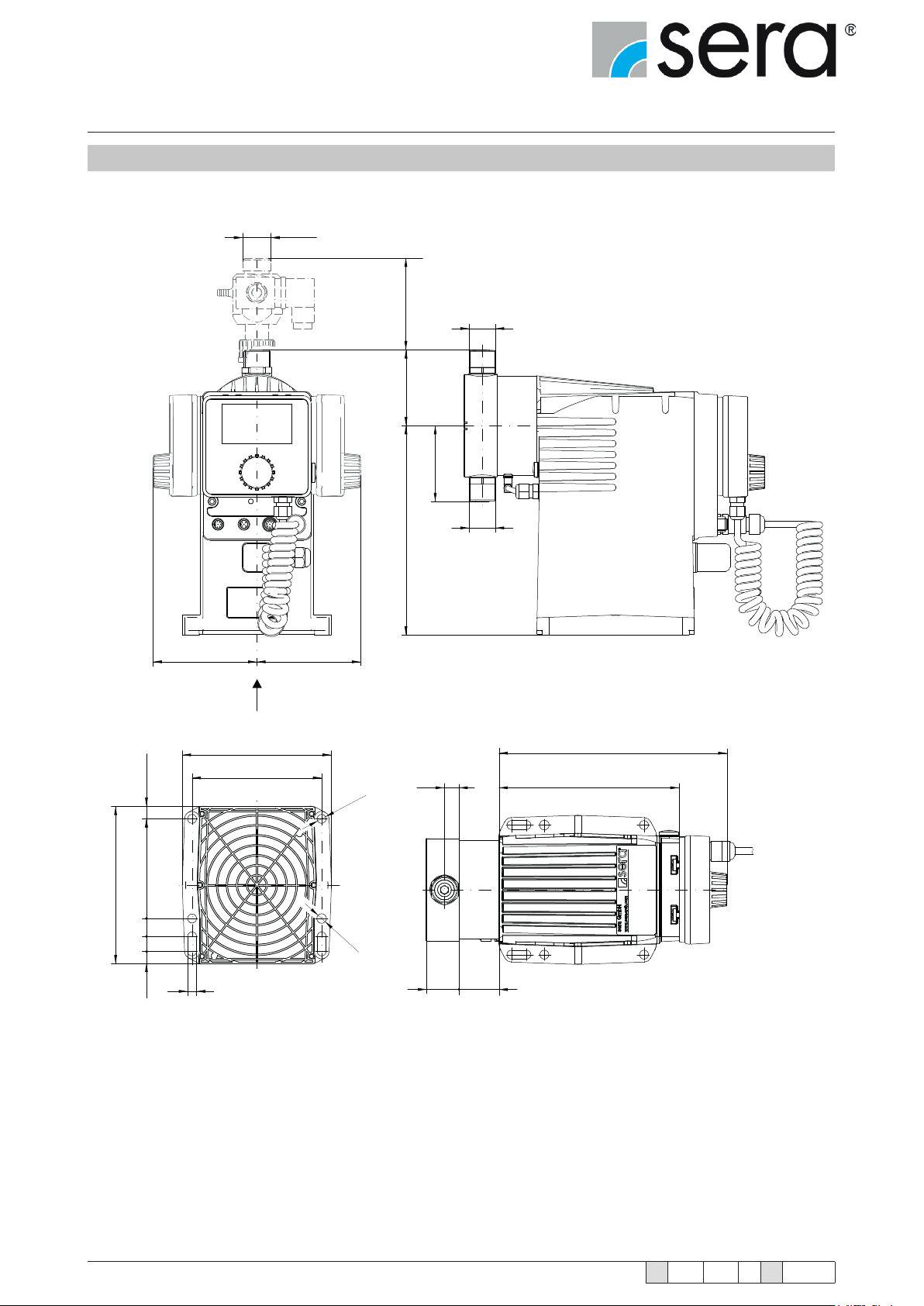
5.3 Dimensions
G3/4
88
G
D
S
157,9
X
(12,5)
10018
15
105 105
X
149,5
130
210
G
230
B 181
Ø 9
Ø 9
22
12,4
9
www.sera-web.com
C A
Subject to technical modications!
TA 508 Rev. 00 en 11/2015
Stepper motor pump
®
iSTEP
Operating Instructions
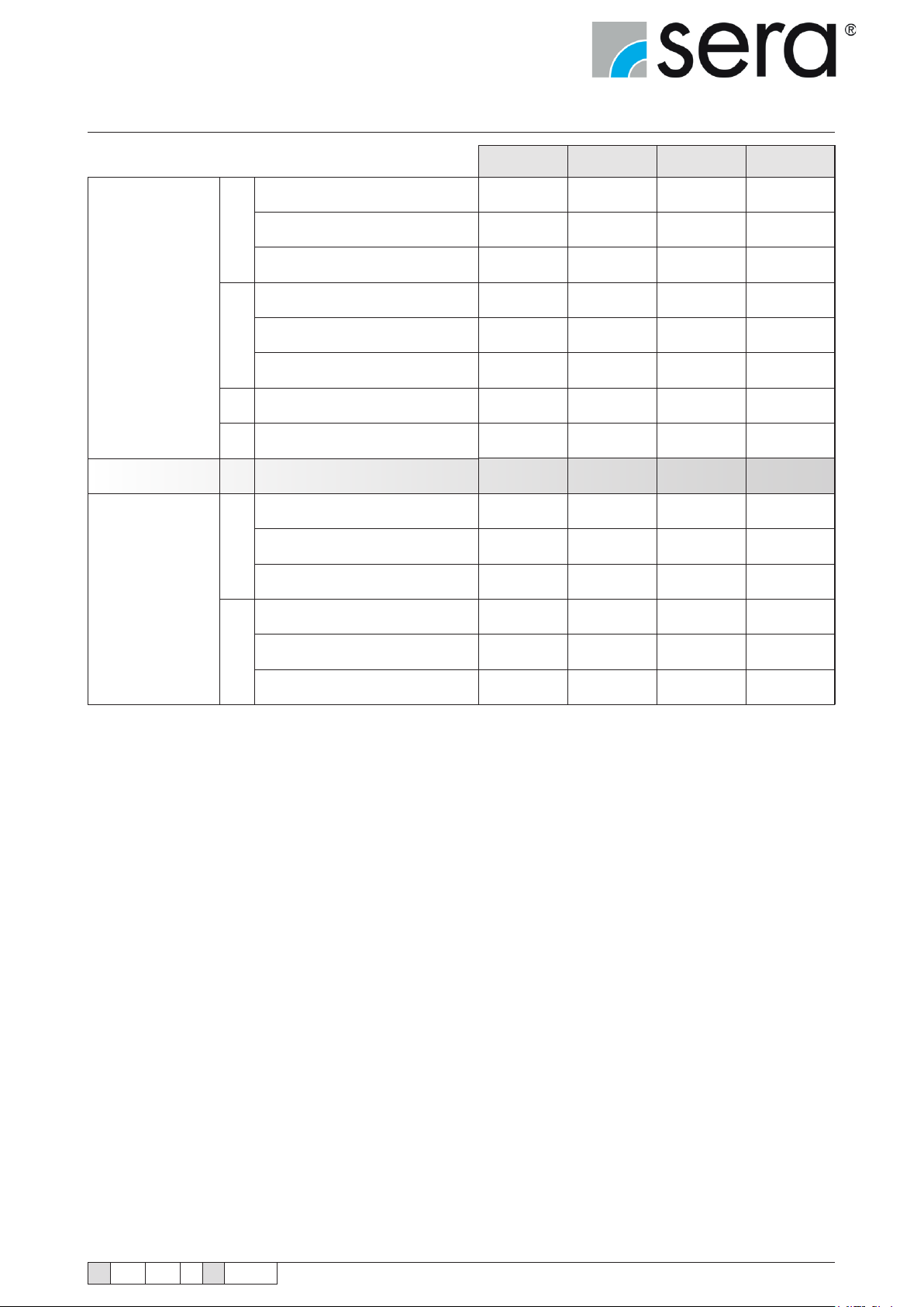
All dimensions in mm!
Valves
Assembly pump A Assembly pump
Pump body (PB)
Double valves PVC
S
Double valves PP-FRP/ PVDF-FRP
Double valves 1.4571
Double valves PVC
D
Double valves PP-FRP/ PVDF-FRP
Double valves 1.4571
Connection thread
G
Suction/pressure valve
DN Nominal weight
Centre of valve thread
PB PVC
Centre of valve thread
B
PB PP-FRP/ PVDF-FRP
Centre of valve thread
PB 1.4571
iSTEP
®
S 20 iSTEP
®
S 30 iSTEP
®
S 40 iSTEP
65 72 72 75,1
56,6 69,6 69,6 76,1
65 72 72 75,5
65 72 72 75,1
64,6 69,6 69,6 76,1
65 72 72 75,5
G3/4 G3/4 G3/4 G3/4
5 5 5 8
37,5 40 40 40
16 14,7 14,7 14,7
17 14,7 14,7 14,7
16 14,7 14,7 14,7
®
S 50
PB PVC
C
PB PP-FRP/ PVDF-FRP
PB 1.4571
38 40,3 40,3 39,3
35 33,2 33,2 33,2
36 38,2 38,2 37,2
TA 508 Rev. 00 en 11/2015
Subject to technical modications!
www.sera-web.com
23
Stepper motor pump
®
iSTEP
Operating Instructions
6. Assembly / Installation
■ The standard model of the pump is only approved for installation in dry areas in a non-aggressive atmosphere and
temperatures between 0 °C and +40 °C and humidity of 85% (short-term 100%), max. installation height 2000m
above sea level.
If toxic, crystallising or corrosive liquids are conveyed the pipe system must be
equipped with facilities for emptying, cleaning and if necessary rinsing with an appropriate medium.
DANGER!
Mount the dosing pump so that leaking medium cannot cause any damage.
WARNING!
■ Protect the pump from heat sources, direct sunlight and UV light.
■ See “Dimensions” chapter for dimensions of the pump connections and xing holes.
The use of washers is recommended for xing the pump. The mounting area must be at and have adequate load-
bearing capacity.
■ Fixing the pump with at least four bolts above the pump base is required for safe operation.
■ Install the pump so that there is no vibration and no tension and that it is aligned precisely.
■ Install the pump at the optimum possible operating height. Mount the pump so that the valves are vertical.
■ Ensure that there is sufcient space around the pump body and the suction and pressure valve so that these parts
can be easily dismantled if required.
■ Design the nominal diameters of the downstream piping and the valves installed in the system to be the same size
or larger than the nominal inlet and outlet diameters of the pump.
■ To check the pressure ratios in the piping system, it is recommended to provide connections for pressure measure-
ment ttings (e.g. manometers) near the suction and pressure ports.
■ Drain valves must be provided.
■ Before connecting the pipes, remove the plastic caps on the suction and pressure ports of the pump.
■ Check the fastening bolts for the pump body for tightness and tighten if necessary, see “Overview of the tightening
torques” chapter.
■ Connect pipes to the pump so that there are no forces acting on the pump, such as e.g. misalignment, weight or
strain of the pipe.
■ Keep the suction pipes as short as possible.
■ Use pressure and medium resistant hoses / pipes.
■ All pipes and containers connected to the pump must comply with the regulations and must be cleaned, tension-free
and intact.
WARNING!
24
The pump must be adequately fastened at the installation site.
www.sera-web.com
Subject to technical modications!
TA 508 Rev. 00 en 11/2015
Stepper motor pump
®
iSTEP
Operating Instructions
In order to avoid cavitation, overload or excessive delivery, the following points should be noted:
■ Avoid high suction heights.
■ Keep pipes as short as possible.
■ Select sufciently large nominal diameters.
■ Avoid unnecessary choke points.
■ Install a pulsation damper.
■ Install overpressure protection.
■ Install a pressure-sustaining valve, if necessary
■ Provide feed line for outgassing media.
Bei Zulauf sind vom Betreiber geeignete Schutzmaßnahmen (z.B. Auffangwanne) zu
ergreifen, damit im Falle eines Membranbruches ein Leerlaufen des Behälters vermieden wird.
WARNING!
WARNING!
DANGER!
Install the return line of overpressure protection and/or ventilation valve sloping
downward into the associated tank.
The pump is only designed for operation outside Ex-zones!
TA 508 Rev. 00 en 11/2015
Subject to technical modications!
www.sera-web.com
25
Stepper motor pump
®
iSTEP
Operating Instructions
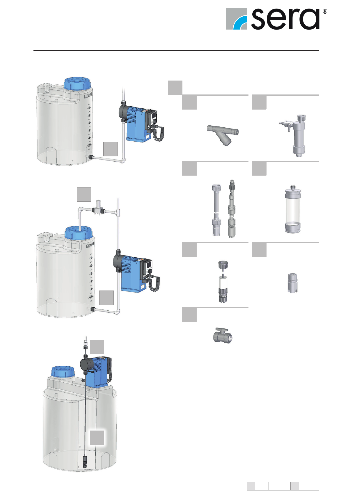
The following fittings can be used on the
suction side:
1 SUCTION SIDE
2.7
1.1 Line strainer 1.2
Suction aid
Siphon vessel
1
1.3 Suction lance 1.4 Multifunction device
1.5 Dosing set 1.6 Foot valve
2.10
1.5
1
1.7 Shut-off valve
26
www.sera-web.com
Subject to technical modications!
TA 508 Rev. 00 en 11/2015
 Loading...