

Page 1

LISST-100X
Particle Size Analyzer
User’s Manual
Version 4.65
2700 Richards Road, Suite 107
Bellevue, WA 98005-4200
Tel: (425) 641-0944 Fax: (425) 643-0595
Page 2
© This document is copyrighted by SEQUOIA SCIENTFIC, INC.
Page 3

LISST – 100 User’s Guide
Welcome to the LISST-100X Particle Size Analyzer
Using this manual
This manual is divided into two sections.
Section One contains an introduction to the LISST- 100
instrument and the principles of its operation.
Section Two provides a detailed set of instructions for using
and caring for the instrument.
Instrument specifications
For a listing of instrument-specific constants, as used in the
software for data processing, refer to Appendix A.
Technical assistance
For technical assistance please contact your local Distributor or
a Sequoia Technical Service Representative listed below.
Please be sure to include the instrument serial number with any
correspondence.
Factory Technical Service Representatives
Chuck Pottsmith
[email protected]; (425) 641-0944 ext.107
Doug Keir
[email protected]; (425) 641-0944 ext.104
Page 4

Page 5

Table of Contents
SECTION 1: INTRODUCTION TO THE LISST-100X ............................................................................. 2
INTRODUCTION ............................................................................................................................................ 2
GENERAL DESCRIPTION ............................................................................................................................... 5
SECTION 2: OPERATION ........................................................................................................................ 8
GETTING STARTED ...................................................................................................................................... 9
STEP BY STEP PROCEDURES ....................................................................................................................... 23
Step by Step Procedure: Record and Store Background Scatterfile ................................................... 24
Step by Step Procedure: Offloading/Deleting Data Files ................................................................... 26
Step by Step Procedure: Processing raw data .................................................................................... 28
Step by Step Procedure: View processed datafile ................................................................................ 32
Step by Step Procedure: Real-time data processing ........................................................................... 35
Step by Step Procedure: Configuring data collection ........................................................................ 38
INSTRUMENT COMMUNICATION ................................................................................................................ 43
LISST-100X COMMAND SUMMARY ......................................................................................................... 47
LISST-100X COMMAND DETAILS ............................................................................................................ 48
PERFORMANCE OPTIMIZATION .................................................................................................................. 54
INSTRUMENT MOUNTING ........................................................................................................................... 57
INSTRUMENT STORAGE & MAINTENANCE ................................................................................................. 58
TECHNICAL SPECIFICATIONS ..................................................................................................................... 62
APPENDIX A: INSTRUMENT SPECIFIC DOCUMENTATION ........................................................... 63
APPENDIX B: DATA STORAGE FORMAT AND SIZE RANGES ......................................................... 64
APPENDIX C: CONNECTOR PINOUTS FOR LISST-100X ................................................................... 66
APPENDIX D: LISST-SOP SOFTWARE BUTTON DESCRIPTION .................................................... 68
APPENDIX E: SOFTWARE UPGRADE INSTALLATION PROCEDURE ........................................... 69
APPENDIX F: HORZONTAL CHAMBER INSTALLATION PROCEDURE ........................................ 72
APPENDIX G: BIOBLOCK INSTALLATION AND USE ........................................................................ 73
WARRANTY ............................................................................................................................................... 77
1 LISST – 100X User’s Guide
Page 6
Section 1: Introduction to the LISST-100X
Introduction
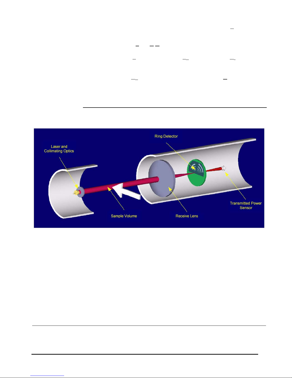
Principle of
Operation
A collimated laser
beam enters water,
light is scattered by
particles and sensed
by a multi-ring
detector behind a
receiving lens. A
photodiode placed
behind a centered
hole measures
optical transmission
The product name LISST is derived from the term that describes
its operation: Laser In-Situ Scattering and Transmissometry.
LISST is a Trademark of Sequoia Scientific, Inc.
The LISST-100X instrument uses the technique of laser
diffraction to obtain particle size-distribution (PSD), also called
volume distribution in this manual. This section describes the
principle of operation of your instrument.
The laser diffraction method for sizing particles was invented in
the 1970’s and rapidly became the most widely used optical
method for determining size distribution for the simple reason
that for laser diffraction, the composition or refractive index of
the particles is not important. This method determines size
distribution of an ensemble of particles, as opposed to counting
type devices that size one particle at a time. The reason that laser
diffraction is unaffected by composition of particles is that the
scattering of laser light is observed at multiple, small forward
angles. At these small angles, light scattering is determined
almost entirely by light diffracted by the particle. The light
transmitted through the particle makes only a weak contribution
to the measured scattering. Since the light transmitted through the
particle would experience the composition of the particle, i.e. its
refractive index, and since it makes only a weak contribution
to the observed scattering, the method of laser diffraction is
mostly independent of particle composition. In the aquatic
sciences, particle refractive index is poorly known. Thus, except
for shape effects, laser diffraction offers an excellent method for
size-distribution estimation. Shape effects are a matter of
continuing research and no definite generalized guidelines are
available to account for them by any method. Consequently, laser
diffraction methods deliver the equivalent-spheres size
distribution. By calibrating for concentration with ISO standard
natural particles, shape effects are empirically included.
LISST – 100 User’s Guide 2
Continued on the next page...
Page 7

The LISST-100X records the scattering intensity over a range of
small angles using a specially constructed multi-ring detector
shown in the graphic above. This measurement is also known to
optical scientists as the volume scattering function and can be
used as such for studies of underwater image propagation and
beam spread. A growing number of publications of measurements using the LISST-100X instrument is available on our
website: http:www.sequoiasci.com.
The conversion of the multi-angle scattering to size distribution
involves a mathematical inversion. In this step, a sizedistribution is found that would produce multi-angle scattering
that fits the observation. There exists a vast literature on the
subject of this inversion. For the stout-hearted user interested in
learning all about it, we recommend the most germane study of
the subject:
"Optimal scaling of the inverse Fraunhofer diffraction
particle sizing problem: The linear system produced by
quadrature," by E. D. Hirleman, Particle Characterization,
4, 128-133, 1987.
The main conclusions are that the information content of the data
is most stably retrieved by use of ring-type detectors, with each
ring measuring the scattering over a sub-range of angles, and that
the resolution is limited to relatively few size classes depending
on the noise in the data. For example, for the dynamic range in
scattering angles of 200:1 that is built into the LISST systems,
typically only 12-14 truly independent size classes can be
resolved.
Simpler descriptions of principles and practice are offered in a
separate study by Agrawal et al., 19911. A more up to date
description of the technology and its application is provided by
Agrawal & Pottsmith, 20002.
We explain the inversion process as follows: Let E
be the 32element data vector that contains the angular scattering energy
sensed by the 32 silicon rings. It is related to the volume
distribution3 via
E = K NV
where K
volume distribution.
1
Agrawal, Y.C., I.N. McCave, and J.B. Riley, 1991: "Laser diffraction size analysis," in Principles, methods and applications of
particle size analysis, J.P.M. Syvitski, editor, Cambridge University Press, pp. 119-128.
2
Agrawal, Y. C. and H. C. Pottsmith, 2000: Instruments for Particle Size and Settling Velocity Observations in Sediment Transport,
Marine Geology, 168
3 LISST – 100X User’s Guide
, pp 89-114.
is the scattering property kernel matrix and NV is the
Page 8
The volume distribution is obtained by inverting the above
equation. To test whether the estimated solution is a good one,
one may compute the prediction of a scattered energy estimate Ee
as
E
= K Ne
e
If the measurements E
are consistent with Ee , the estimates of Ne
can be considered good. Included with the LISST-100X
instrument, we have provided software that obtains the inverted
volume distribution N
. We have also provided the matrix K for
V
your instrument (in ASCII and MATLAB® formats) in order for
you to test your results.
3
The volume distribution is related to the number distribution via NV = a3 n(a). It represents the volume concentration of particles
of particles in the size range a to a + da. The results from the LISST instruments provide the volume concentration of particles in
each of 32 size classes. The size classes are log-spaced from the range 1.25-250 microns (Type-B instruments), 2.5-500 (Type-C),
or 7.5-1500 microns (Type-D, LISST-FLOC). See Appendix B for further details.
LISST – 100 User’s Guide 4
Page 9

General Description
General layout
The LISST-100X instrument is a laser diffraction device. It
consists of optics for producing a collimated laser beam, a
specially constructed detector array, electronics for signal preamplification and processing, a data storage and scheduling
computer, and a battery system.
The instrument is capable of autonomous operation. For such
operation, software is provided to program the instrument for a
specific sampling schedule. The primary measurements delivered
by the LISST-100X are the small-angle scattering properties of
particles in water, the laser optical transmissivity, depth, and
temperature. An auxiliary Analog port is available for recording
data from an external input.
After recovery of the instrument, small-angle scattering data are
off-loaded from the instrument and subsequently inverted
mathematically on a PC to produce the particle size distribution.
The inversion function is included in the software.
The principal measurement—angular scattering distribution— is
obtained over 32 ring-detectors whose radii increase
logarithmically from 102 to 20,000 microns. The detector is
placed in the focal plane of the receiving lens. The rings cover an
angular range from 0.0017 to 0.34 radians (Type-B), 0.00085-
0.17 (Type-C), or 0.00028-0.053 radians (Type-D, or LISSTFLOC) . This angular range corresponds, respectively, to size
rangesL 1.2 to 250 microns (Type-B), 2.5-500 (Type-C) and 7.51500 microns (Type-D, or LISST-FLOC).
This self-contained instrument consists of the following parts: a
solid-state laser operating at 670nm wavelength and fiberoptically connected to a laser beam collimating system, a beam
manipulation and orienting system, a scattered-light receiving
lens, the specially designed 32-ring detector, preamplifier
electronics, a ring-selecting multiplexer circuitry, and a data
logger.
Depth and
Temperature
In addition to measuring the particle size and concentration, the
LISST-100X also has built-in Depth and Temperature sensors.
The Depth sensor is a 500 psi strain gauge sensor. The stainless
steel fitting on the Connector endcap is used for testing this
sensor. It is not required for normal operation. However,when not
used for testing, this fitting helps keep contamination out of the
pressure sensor. The temperature is measured using a high
precision thermistor imbedded into the Connector end cap. Both
values are stored automatically in the standard-format LISST100X datafile.
5 LISST – 100X User’s Guide
Page 10
External I/O Ports
The LISST-100X is also equipped with an external ANALOG IN
port for recording the output of one other analog instrument.
Additionally, 2 DIGITAL I/O ports are provided for
communicating with up to two instruments. The I/O ports can be
used for synchronization of the LISST-100X with two other
instruments; e.g., the LISST-100X may provide a timing pulse to
a CTD, or it may provide a 'start sample' pulse to another LISST100X. The same ports can be used to receive similar commands.
Contact Sequoia Scientific for more information on interfacing
the LISST-100X with other instruments. These ports are available
on the 6-pin underwater connector on the Connector Endcap.
Appendix C shows the connector pinouts. The instrument can be
configured to use the Digital I/O ports as a trigger to start and
stop sampling.
Battery Life
The primary power source for the LISST-100X is a custom
alkaline D-cell battery-pack. The pack outputs +9 volts. It has a
room-temperature capacity of 42 A-hr. When the instrument is in
stand-by mode, (i.e., displaying the L100X> prompt) the current
drain is 8.5 mA. In Low Power Sleep mode the current drain
drops to 120 µA. For profiling applications, where the
instrument is sampling continuously, the battery pack has about
60 hours of “On” time. Powering down the instrument between
samples can greatly extend the deployment times. An EXCEL
spreadsheet is included with the software that can estimate the
battery consumption
For laboratory or tethered usage, a connector is provided on the
endcap to draw power from an external source. The voltages
required from the external power supply are +9. Cables up to 50
meters can be provided to supply external power and
communication with the instrument. This can allow Real-Time
observation of the Size Distributions.
When not in use, use the Low Power Sleep mode of
the instrument to reduce battery drain to about
10μA. This can be done from the provided
software.
LISST – 100 User’s Guide 6
Page 11
Auxiliary
Equipment
The instrument is shipped pre-aligned and tested. A chamber is
provided for obtaining measurements of background scattered
light from optical surfaces. This background is subtracted from
actual particle scattering measurements to obtain the true
particulate scattering. Additionally, small tools used to open
endcaps, spare batteries, and communication cable are supplied so
that a user need only provide a PC.
Software is provided to communicate with the instrument,
schedule an experiment, offload the data, and invert the
measurements to obtain particle size distribution and volume
concentration. For laboratory use or for monitoring the progress
of an experiment, the software can be used for real-time
processing.
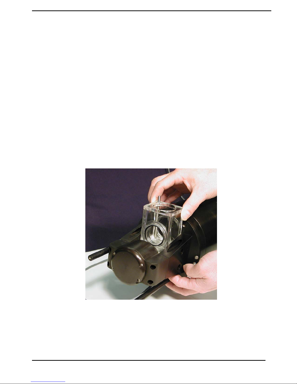
For laboratory testing an optional Small Volume Full Path Mixing
Chamber is available. This chamber mounts to the optics of the
LISST-100X and seals around the windows of the instrument.
The sample can then be added to the chamber and the built-in
mixer will keep the sample mixed with the measurements are
being made. The picture below shows the chamber being installed
onto the LISST-100X.
7 LISST – 100X User’s Guide
Page 12
Section 2: Operation
Section
Organization
General
Precautions
Section 2 is divided in to two main sections. The first section is
the Getting Started section. This section will walk the user
through using the instrument from opening the shipping case
through processing downloaded data. Reading the Getting
Started section will give most users enough information to
starting using the instrument. Following the Getting Started
section are detailed instructions for performing various
procedures
LISST-100X is a sensitive optical instrument. Please handle it
gently. Critical alignments may be disturbed if the instrument is
subjected to shock or rough handling. Evidence of shock/rough
handling will void the warranty. Whenever in transit, store the
instrument in the provided padded shipping case.
WARNING
The LISST-100X uses a laser diode emitting a maximum of 1 mW
of visible (red) light at a wavelength of 670nm. the laser beam
under normal circumstances is not a threat. However, if objects
are placed in the path of the laser beam, the light could be reflected
into the eye causing permanent damage.
.
LISST – 100 User’s Guide 8
Page 13

Getting Started
Contents of
shipping case
Step 1: Remove
Instrument from
shipping case.
This section is designed to give the user a quick introduction to the
operating procedures for the LISST-100X. It gives step by step
instructions to unpack, load software, and acquire data in the lab.
Following the introduction are details on each step of the process.
Let’s assume that you are opening the LISST-100X shipping cases for
the first time. Inside you will find the following: User’s Manual with
software disk, LISST-100X instrument, Plastic Instrument stands, Small
Volume Horizontal Test Chamber, Communications cable, External
Power cable, and Allen wrench set.
Start by removing the white plastic instrument stands and set them on a
flat working surface. Remove the LISST-100X from the case and set it
on the stands. The LISST-100X has two distinct ends that we will refer
to as the Optics endcap and the Connector endcap. The connector
endcap has three underwater connectors that are used for communication.
external power, and connecting to optional accessories or instruments.
The battery pack is attached to the inside of this endcap. The optics
endcap contains the optical windows that the laser beam passes through
to make a measurement. The internal optics and electronics are mounted
to the inside of this endcap.
Step 2: Check for
clean windows
Step 3: Attach the
Communications
Cable
Step 4: Install the
Horizontal test
At this time let’s check the optical windows to make sure that they are
clean. There are two windows. The Receive window is mounted in the
center of the optics endcap. Transmit window is located in the Crossbar
suspended above the endcap. The best way to check the windows is by
using a flashlight. By shining light from one side and viewing from the
other the surface of the windows can be easily checked for cleanliness. If
there is dirt or fingerprints on the windows clean them first by rinsing
them with water and then by wiping them with a soft cloth and alcohol.
Stronger solvents, such as acetone, can be used if necessary but is not
recommended as a general practice. Liquid dish soap can also be used. In
general, do not use any abrasive cleaners or wipes. Treat the windows as
you would an expensive camera lens.
Remove the Communications cable from the shipping crate. It is the
cable with the 9-pin DB-9 connector on one end and the 5-pin
underwater connector on the other. Remove the underwater cap from
the Communications connector. The connectors will all look similar.
The Communication connector is the only 5-pin connector. If the unit
is rotated so that the metal zinc anode is located at the top (or North),
the Communications connector will be on the left (or West). After
removing the cap install the cable making sure that the proper
alignment is maintained.
Remove the Small Volume Horizontal test chamber from the shipping
case if not already installed on to the instrument. Attach the flexible
9 LISST – 100X User’s Guide
Page 14

chamber
Step 5: Install the
provided software
Step 6: Start
LISST_SOP
program
tubing and tubing stop clamp. This chamber is designed to slip
between the optical windows of the instrument such that the optic can
be submerged for testing or calibration. For more information on
installing the see Appendix F. We can now fill the chamber with clean
filtered water. We use steam-distilled bottled water filtered through a
0.2 micron filter. Tap water may contain too many particles and may
also contain dissolved gas that can release and form small bubbles on
the optical surfaces.
At this point instrument is ready to go. Let’s install the software that
is required for operation of the instrument. A software disk is
included with each instrument. In addition to the communication and
processing program the disk also contains calibration files specific for
your instrument. Follow the installation instructions in the
README.TXT file on the disk to install the software.
Start the LISST-SOP software by selecting it from the Start menu.
The name LISST-SOP refers to the Standard Operating Procedure
functionality of the program. Users with experience on previous
versions of the LISST-100 software may find the Appendix E, What’s
New in Version 4.XX a good introduction to the software. Appendix
D has a table describing the functions of each button. It is highly
recommend that existing users who are upgrading to Version 4.60
from earlier versions (Versions 3.xx) of the LISST software read
Appendix F before continuing. There are a number of steps that must
be performed before the software will function correctly with older
instruments.
Step 7: Wake up
instrument from
Sleep mode
The instrument is shipped in a low power Sleep mode to conserve
battery power. To wake up the instrument select Wake Up LISST
from the LISST menu. A dialog box will appear counting down the
maximum time required for the instrument to wake up. The
instrument sleeps for 30 seconds, wakes up for 1 second to look for a
wake up command and then goes back to sleep. Therefore the wait
could be as long as 32 seconds for the LISST-100X. Upon wake up
the instrument status will be displayed. If the cable connections are
not correct or if the battery is not installed a warning message will
appear after the time expires. The serial port settings can be checked
by selecting Serial Port Settings from the Communication menu. The
default settings are COM1, 9600 baud, 8 data bits, No parity, 1 stop
bit, and no protocol.
LISST – 100 User’s Guide 10
Page 15
Step 8: Open
Terminal window
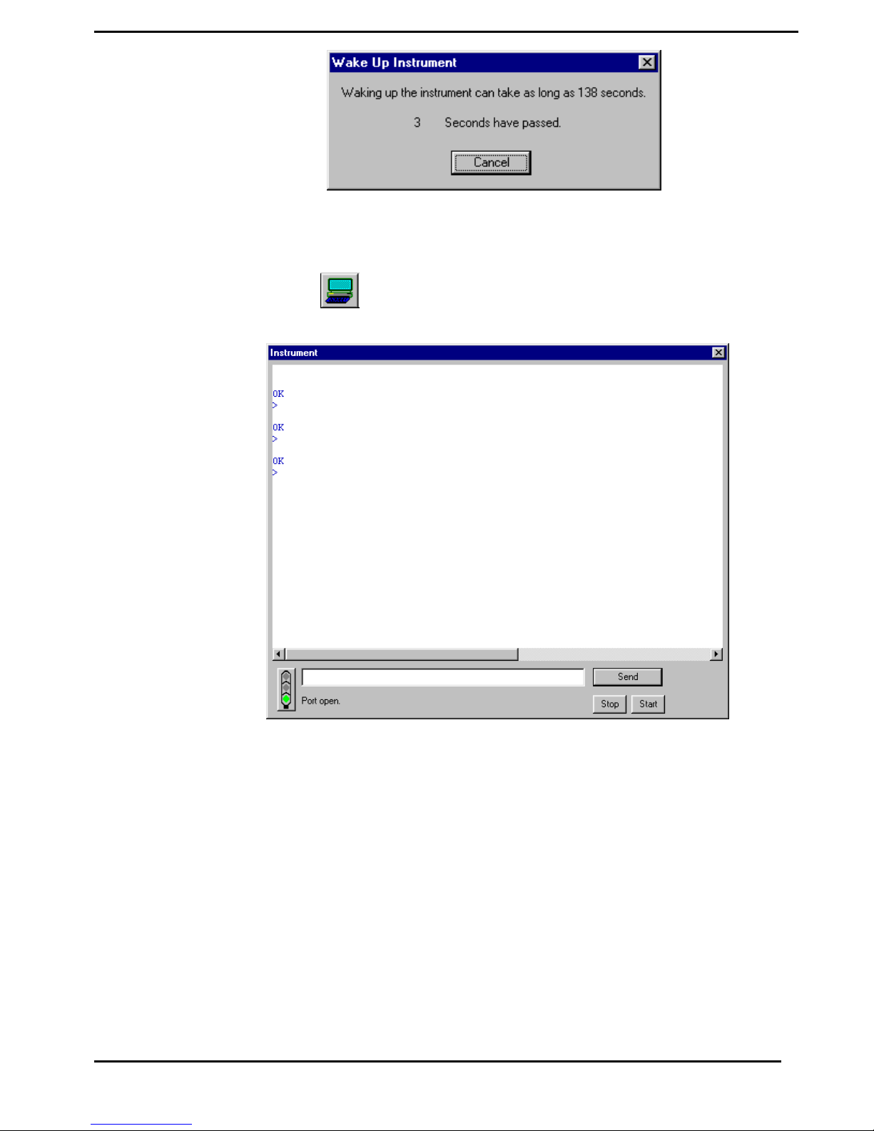
The LISST-SOP has a terminal window that allows the user to
communicate directly with the instrument. To open the Terminal
window select Terminal Window from the Communications window or
select the
button form the tool bar. A window similar to the one
shown below will appear.
Commands can be typed into the box in the lower section of the
window. When the Enter key or the Send button is pressed the
command will be sent to the instrument. The Start button sends a GO
command to the instrument to start the instrument sampling using the
current settings. The STOP button sends a CTRL-C to stop the
sampling and to turn off the main power.
Pressing enter should bring up an L100X> prompt.
If the instrument is still in the Low Power Sleep Mode it will print ZZZ
to the screen every 30 seconds. To wake the instrument from the
Terminal window, press the Stop button immediately after the ZZZ is
displayed. The instrument will only respond to the Stop button for 1
second after the ZZZ is displayed. After the 1 second the instrument is
in a low power mode and will not respond to commands for another 30
seconds.
11 LISST – 100X User’s Guide
Page 16
Step 9: Intro to the
new Datalogger
The datalogger inside the LISST-100X has recently been upgraded. It
is different from earlier versions of the LISST-100. New instruments
using the new datalogger have been given the name LISST-100X. Units
using the previous version datalogger will be called LISST-100. The
new datalogger of the LISST-100X uses removable Compact Flash
cards. Compact Flash Cards are available with up to 1Gb of memory.
The LISST-100X comes standard with 128Mb. The Compact Flash
Cards can be removed. By using a PCMCIA adapter or USB card
reader the data files can be directly transferred to the PC. The standard
procedure is to offload the files using the LISST-SOP software at 115K
baud.
The LISST-100X now has standard two-letter commands that can be
used for interfacing the instrument with other dataloggers and sensors.
The commands are similar to the commands used with the LISST-25X
instrument. A complete description of the commands is shown in the
LISST-100X Command Summary section.
Step 10: Acquiring
Background
Scattering
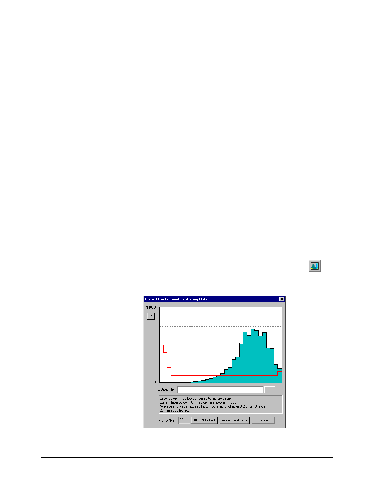
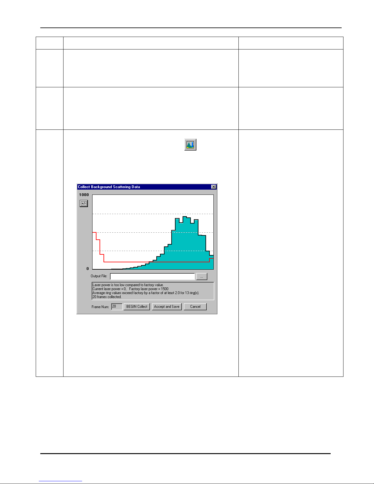
A new feature of the LISST-SOP is the ability to acquire background
scattering in real-time. The background scattering measurement is
critical to good instrument performance. It is especially critical for
clean water applications where the optical transmission is greater than
80% over the 5cm path. The background scattering will also check the
overall health of the instrument. It will verify that all of the systems
are functioning and that the optics are still in alignment. The current
background will be acquired and displayed relative to the factory
background scattering for the instrument. The image below shows an
example of this display. It is opened by either selecting Collect
Background Scatter Data from the LISST menu or by pressing the
button on the toolbar. After selecting the factory background scatter
file to use for comparison the window will display.
When the BEGIN Collect button is pressed 20 samples will be
displayed to the screen as they are acquired. After all 20 are collected
LISST – 100 User’s Guide 12
Page 17
the average will be displayed. If the values are acceptable the values
can be saved to a file. Enter the filename in the box and press the
Accept and Save button.
If there is a problem with the instrument or if the water or windows are
not clean, error messages will be displayed. Dirty water or windows
will generally cause higher values across the middle rings. Large
bubbles or particles in the water can cause higher values on the inner
rings or left hand side of the display. High values on the inner rings
combined with a lower Laser power value can also be an indication of
optical misalignment.
Step 11:
Configuring
Instrument for
Deployment
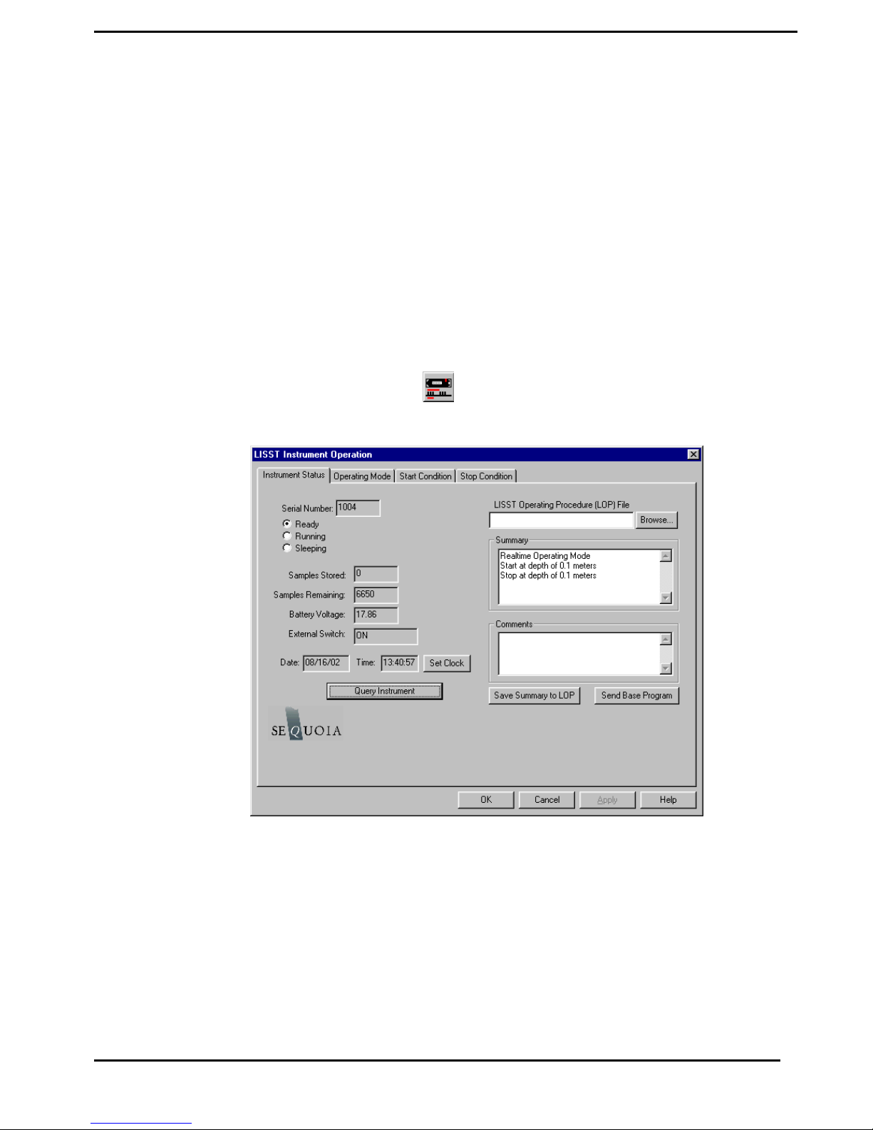
The heart and soul of the new LISST-SOP software is the Operating
Modes window. This window is used to set all of the deployment
parameters. To open the window, choose Operating Modes from the
LISST menu or press the button on the tool bar. A window similar
to the one shown below will appear.
The window has four tabs, Instrument Status, Operating Mode, Start
Condition, and Stop Condition. The Instrument Status page gives
information about the current instrument. It also allows previously
saved instrument configuration files to be loaded on to the instrument.
The ability to save the current settings to a file is also available. The
Summary window shows the current deployment configuration.
Step 12: Setting
Operating Mode
By selecting the Operating Mode Tab at the top of the main window
the screen below appears. This screen is used to set the type of
sampling; RealTime, Burst, or Continuous. You can also select the
13 LISST – 100X User’s Guide
Page 18
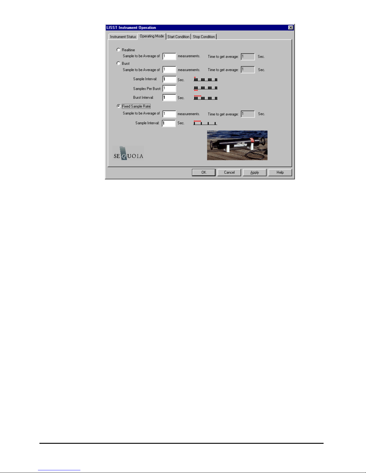
samples per average and sample rates on this screen.
Step 13: Setting
Start Conditions
The RealTime mode is used for real-time size distribution displays.
This mode sends the raw data to the LISST-SOP software for
conversion to Size Distribution and displaying on the screen. No data is
saved in the datafile.
The Burst and Continuous modes are used to save data in the on-board
datafile. The icons next to the various values give a better
understanding of their meaning. The software automatically checks the
values entered to make sure that there is no conflict. For example,
when a Measurements per Average value is entered, the minimum
sample interval is computed. If this value is less than the minimum
permitted the value will be changed to the minimum and the text will
turn red. A similar test is done on the Burst Interval setting.
For this example let’s set the instrument to sample in the Continuous
mode at a 1 Hz rate with 10 measurements per average.
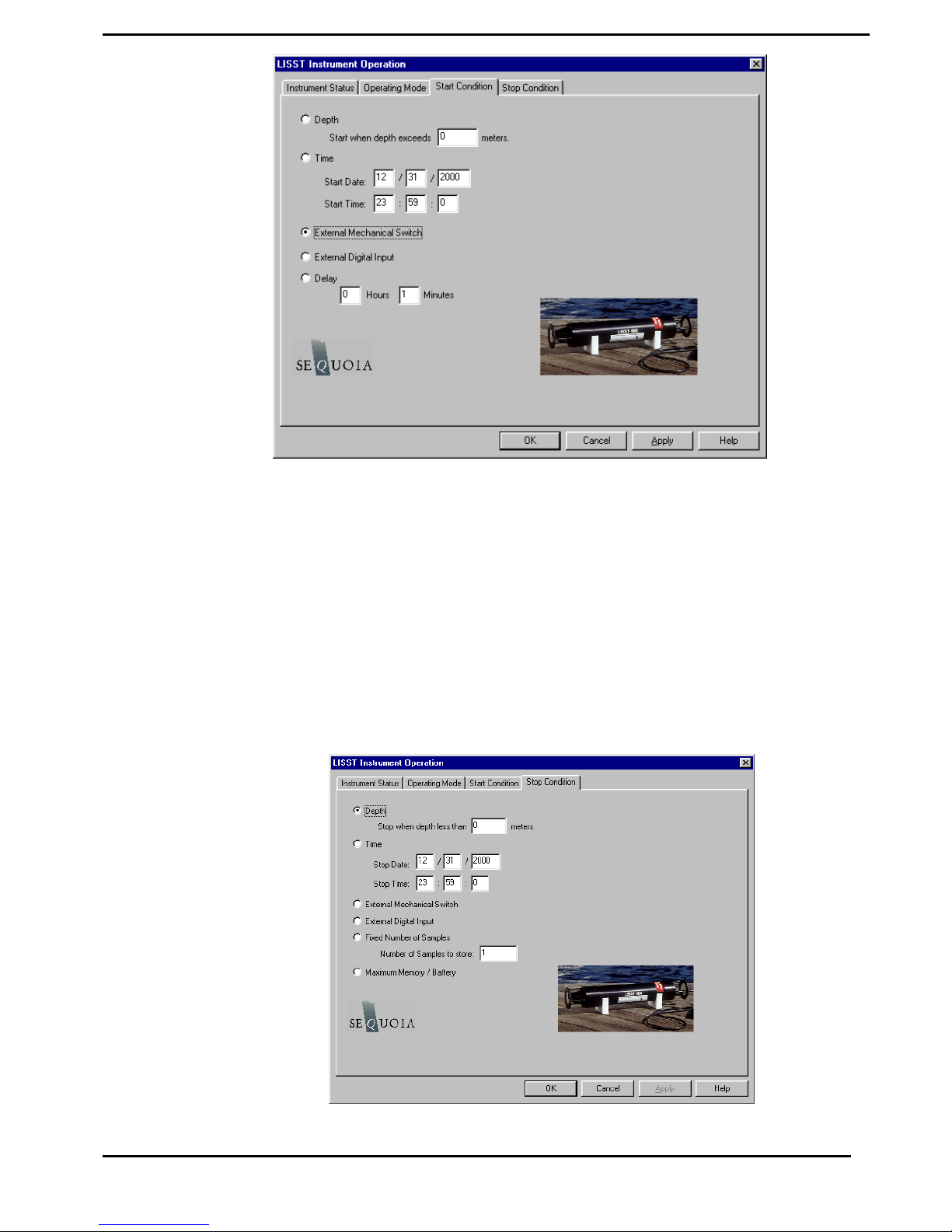
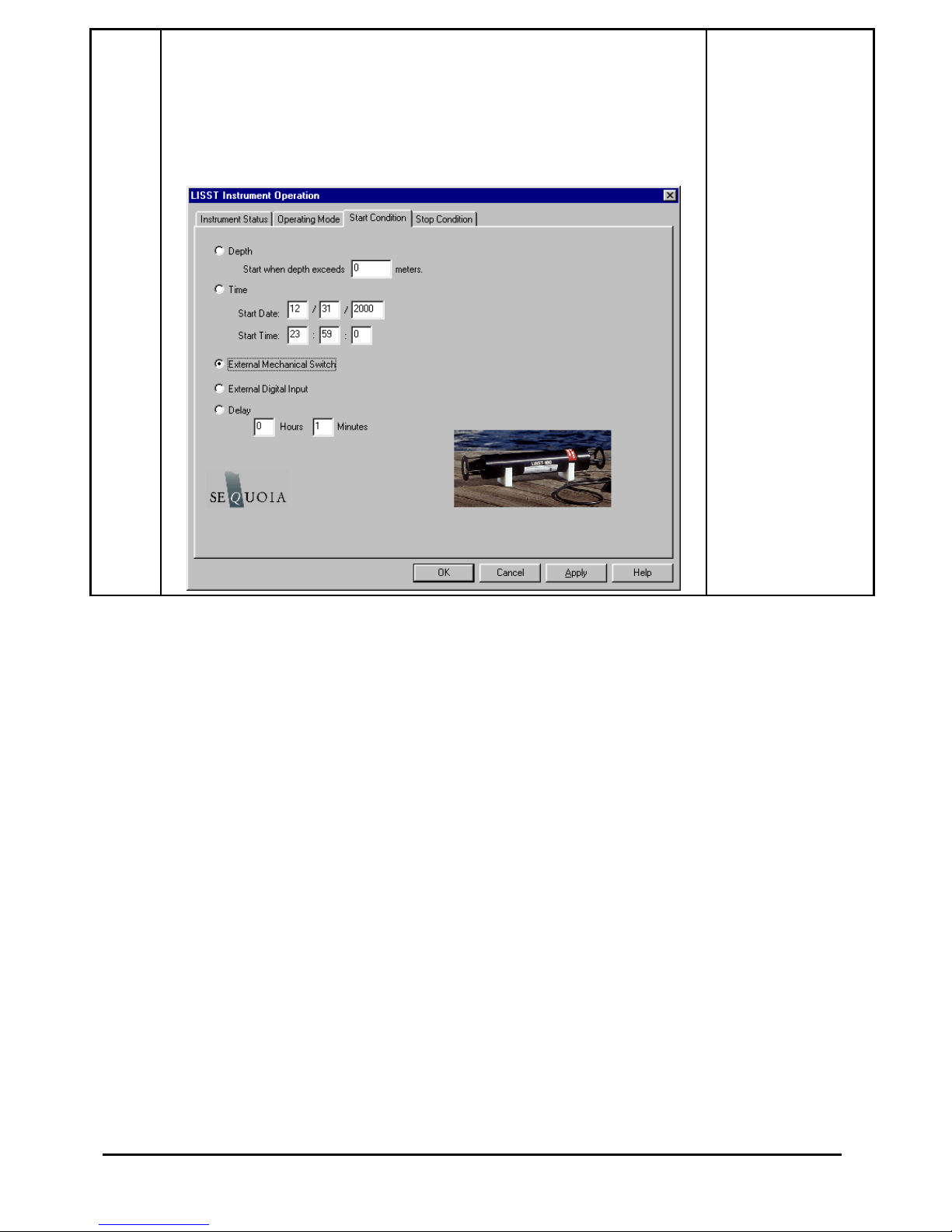
After selecting the Operating mode the start and stop conditions can be
selected. Choose the Start Condition tab at the top of the window.
The Start Condition window, shown below, is used to select the mode
in which sampling will be started.
LISST – 100 User’s Guide 14
Page 19
Step 14: Setting
Stop Conditions
There are five options: Depth, Time, External Mechanical Switch,
External Digital Input, and Time Delay. Select the mode by clicking
on the button next to the its label. Select the correct parameters as
required. For this example let’s select the External Mechanical Switch
Start Condition.
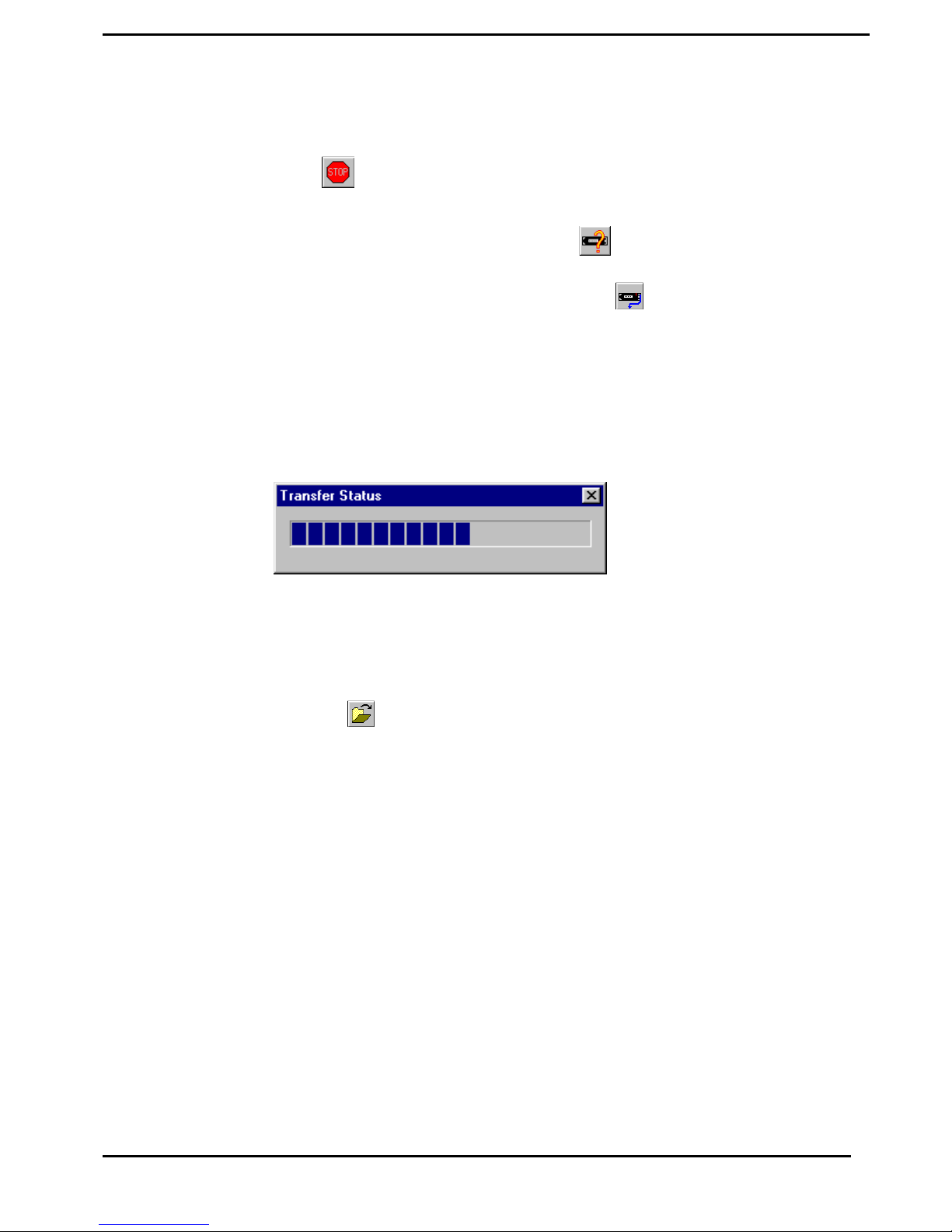
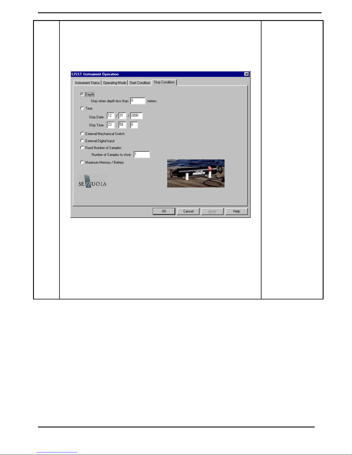
Similarly the Stop conditions can also be selected. Click on the Stop
Condition Tab to open the Stop Condition window. The available stop
conditions are: Depth, Time. External Mechanical Switch, External
Digital Input, Fixed number of samples, and Maximum Memory or
Low Battery.
15 LISST – 100X User’s Guide
Page 20

For this example, choose the External Mechanical Switch as the Stop
condition.
After selecting the Stop Conditions return to the Instrument Status page
by clicking on the Instrument Status Tab.
Step 15: Saving
the settings for
future use
Step 16: Starting
the program
Once the settings have been sent to the instrument the Instrument Status
Page will display the summary of the settings that have been selected.
These setting can be saved for later use by selecting the Save Summary
to LOP. A file name will be prompted for. The file will be given an
LOP extension which will identify it as a LISST Operating Procedure
File. Comments can be entered before saving in the box below the
summary. Previously saved LOP file can be opened using the Browse
button.
Press the Apply button to configure the instrument. This will cause the
settings to be transmitted to the instrument. The configuration will take
about 30 seconds. Once the configuration is completed we can return to
the Instrument Status page to see the summary of the settings and save
them for future use if desired. Press the OK button to complete the
configuration. A prompt will ask if we would like to open the Terminal
window to start the instrument. Choose OK
The instrument is now configured for deployment, however, it is not yet
running. In order for the instrument to respond to the correct Start
Condition the program must be started.
The configuration of the instrument can be checked by selecting Query
Step 17: Collecting
Data
Instrument from the LISST menu or by choosing the button from the
tool bar. A window will appear showing the current status and
configuration. To start the program, press the Start button in the lower
right section of the Terminal window. The program will start and display
text to the screen as it is running. Depending upon the Start Conditions,
text will be displayed approximately every 30 seconds. At this point the
user will know that the instrument is running and is ready to be deployed.
For our example it will be displaying a message that reads “Waiting for
Mechanical Switch ON signal”
When the start conditions are met the instrument will start sampling. The
green LED on the connector endcap will illuminate each time a sample is
acquired.
For our example we can move the white plastic lever on the endcap to the
“1“ position. Sampling will start. If the Terminal window is still open
text will be displayed as the instrument acquires data. Data collection
will continue until the Stop Conditions are met. In our case, until the
switch lever is returned to the “0” position.
If the Start and Stop Conditions are set to Depth, External Mechanical
Switch, or External Digital Input the program will return to checking for
LISST – 100 User’s Guide 16
Page 21
the Start Condition. This will only be true if the Start and Stop conditions
match. For example, Depth Start and Depth Stop. For all other Start
Conditions the program will terminate and return to the L100X> prompt.
To stop a running program use the Stop button on the Terminal window
or the button on the tool bar.
Step 18:
Downloading data
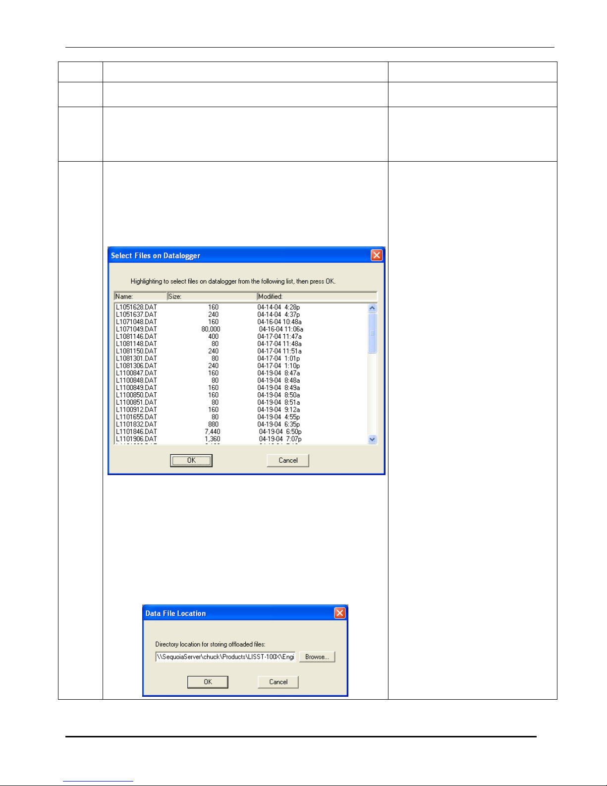
The instrument has now stored data in the on-board Compact Flash card.
Pressing the Instrument Query Button, , will display the instrument
status including the number of samples saved. To offload the data select
Offload from the LISST menu or choose the button from the toolbar.
A list of files will appear. Choose the files to offload by clicking on them
while hold down the CTRL key. The Shift key can also be used to select
a range of files. Select OK and choose a location to save the files to. The
files will be saved with names in the following format: Ldddhhmm.dat,
where ddd is the day of the year, hh is the hour, and mm is the minute that
the file was first written to. As the data is downloading a Transfer Status
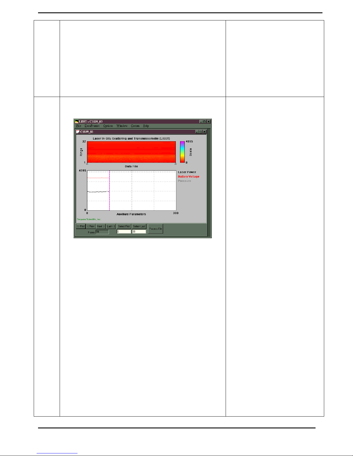
window will appear. The data is offloaded at 115K baud.
Step 19:
Processing Raw
Data
We now have the data transferred from the datafile of the instrument to a
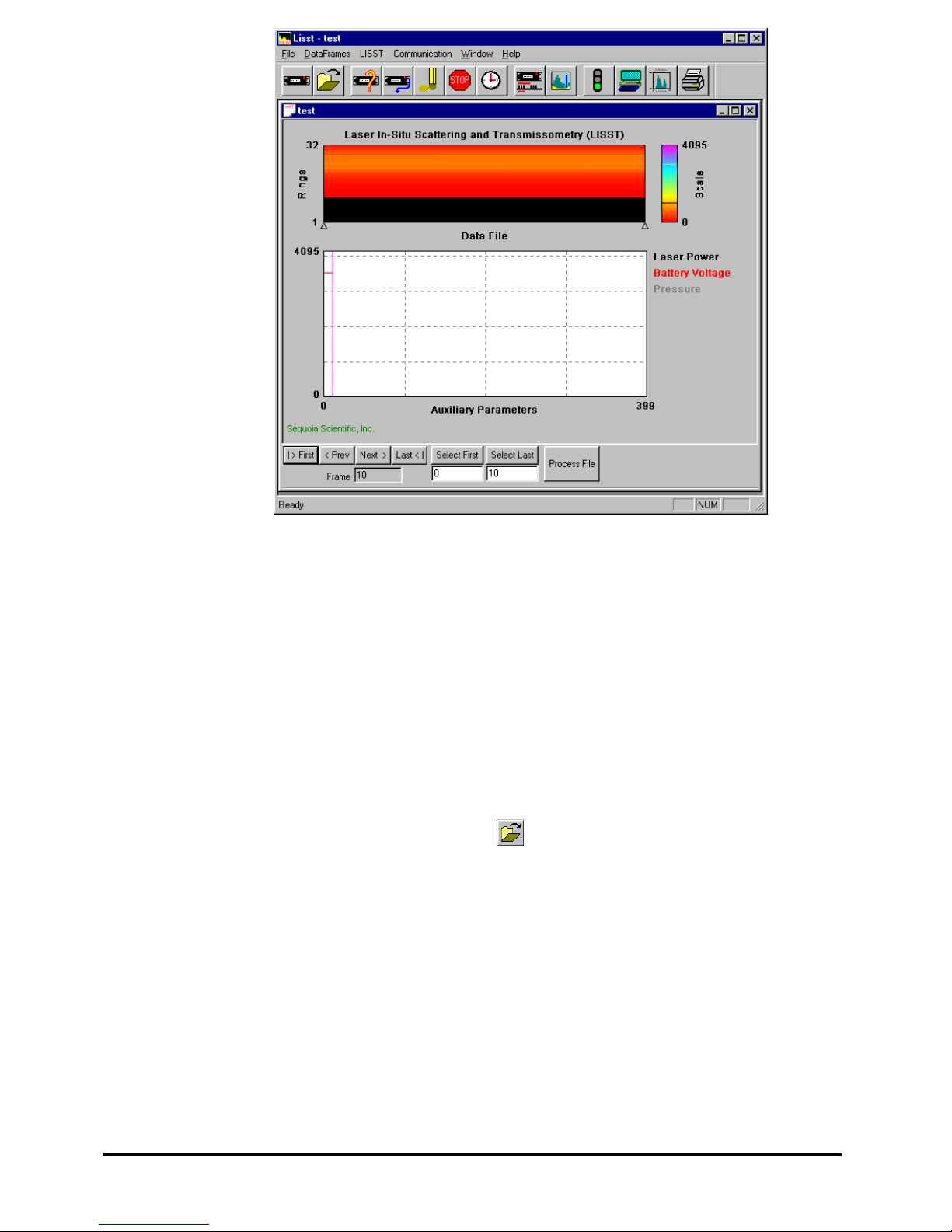
file on the PC. To process the data file choose Open Raw Datafile or
press the button on the toolbar. Select the instrument serial number,
raw data file to open, and background scatter file to use when processing
the data. The software will automatically determine the Instrument Type
(A, B or C) using the Serial Number and the InstrumentData.Txt file.
Unlike earlier versions of the software, the RingArea file (instrument
detector calibration file) is automatically selected based on the serial
number. A display similar to the one shown below will appear
17 LISST – 100X User’s Guide
Page 22
b
The range of samples to process can be selected by entering values in the
Select First and Select Last boxes. The default selection is to process the
complete file. Press the Process File button to convert the raw file into
processed size distributions. For more details on the available options
when this window is open please see the detailed Instruction for
Processing Raw Datafiles. For our example press the Process File button.
When the processing is complete the button label will change to read
Finished.
Step 20: Viewing
Processed Results
Processed data files are stored as ASCII files and as binary files with a
PSD extension. The PSD files can be opened and viewed on the screen.
To open a processed Particle Size Distribution file choose Open Particle
Distribution File or press the
button on the toolbar. A display similar
to the one below should open. The left hand figure will display a bar chart
showing the Volume concentration in each of the 32 log spaced size
classes. The right hand plot will be the Cumulative Concentration. To
view the samples as a movie press the Timer Off button. The slider bar
next to the button adjusts the refresh rate. The First, Prev, Next, and Last
uttons allow you to step through the measurements one frame at a time.
When the last frame is reached the movie display will stop. Use the First
button to return to the first sample and press the Timer Off button to
restart the display.
LISST – 100 User’s Guide 18
Page 23
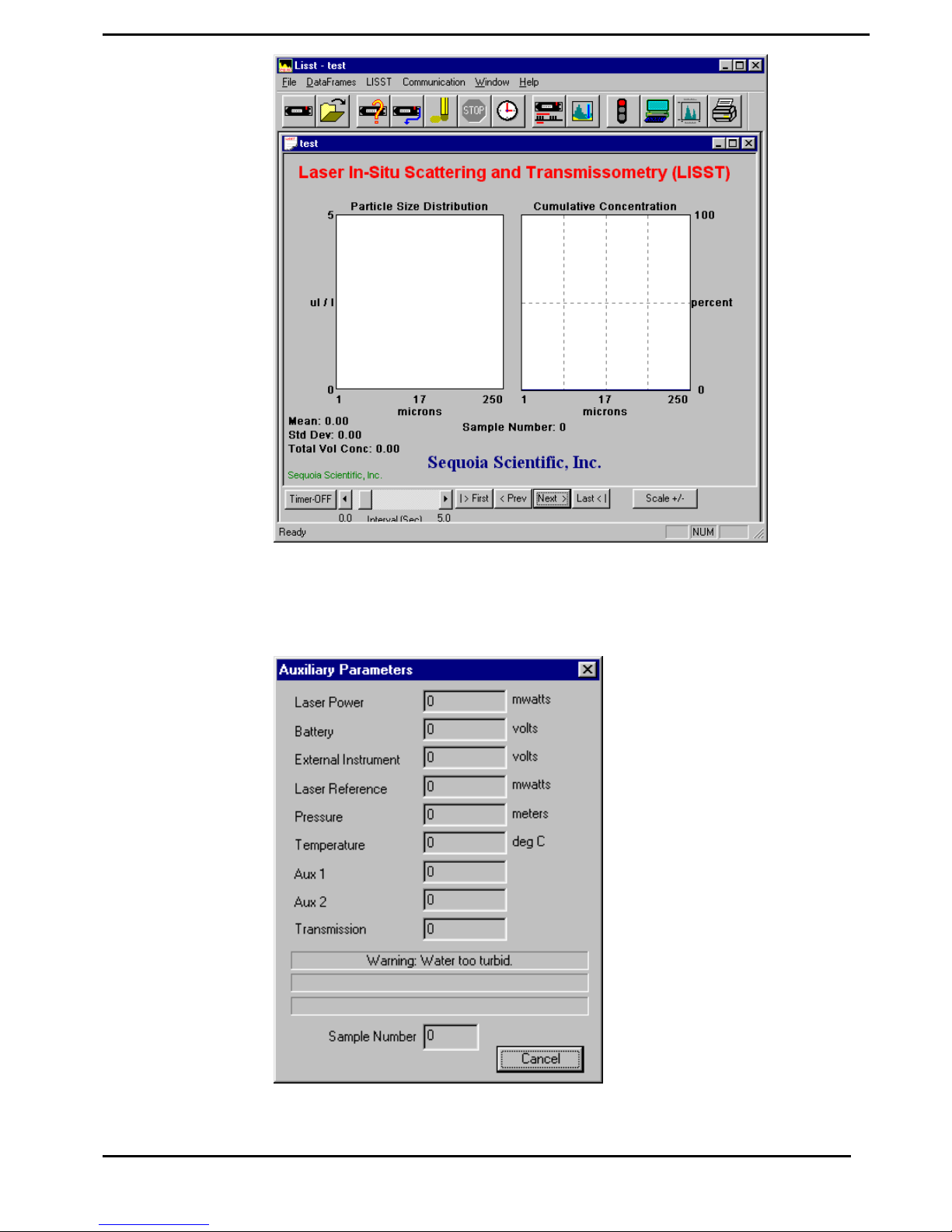
To view the value of the auxiliary parameters, such as time and depth,
select the View Auxiliary Parameter Frame from the DataFrames menu.
A display similar to the one below will appear showing the calibrated
values.
19 LISST – 100X User’s Guide
Page 24
Step 21: Opening
RealTime Session
The LISST-SOP software also supports the ability to acquire data, process
it, and display it in Real-time. The Real-time display of the processed
data is very similar to the display of processed data. The instrument can
be configured for a Real-Time session before data is collected but it is no
longer required. The current setting for Measurements per Average is
used when acquiring the sample to display. The recommend value for the
Measurements per Average is 10. Higher values can be used but the
updating of the display will be reduced. The Start and Stop conditions will
not be used and therefore their settings are not relevant.
NOTE: It is recommended that if extended Real-Time sessions are going
to be done that external power and not battery power be used. The
batteries will be used up fairly quickly during a Real Time session.
When exiting the Real-Time session the power should automatically shut
off. Pressing the Stop button on the toolbar or the Terminal window will
turn off the power. Pressing these buttons when the instrument is already
off will have no ill effects.
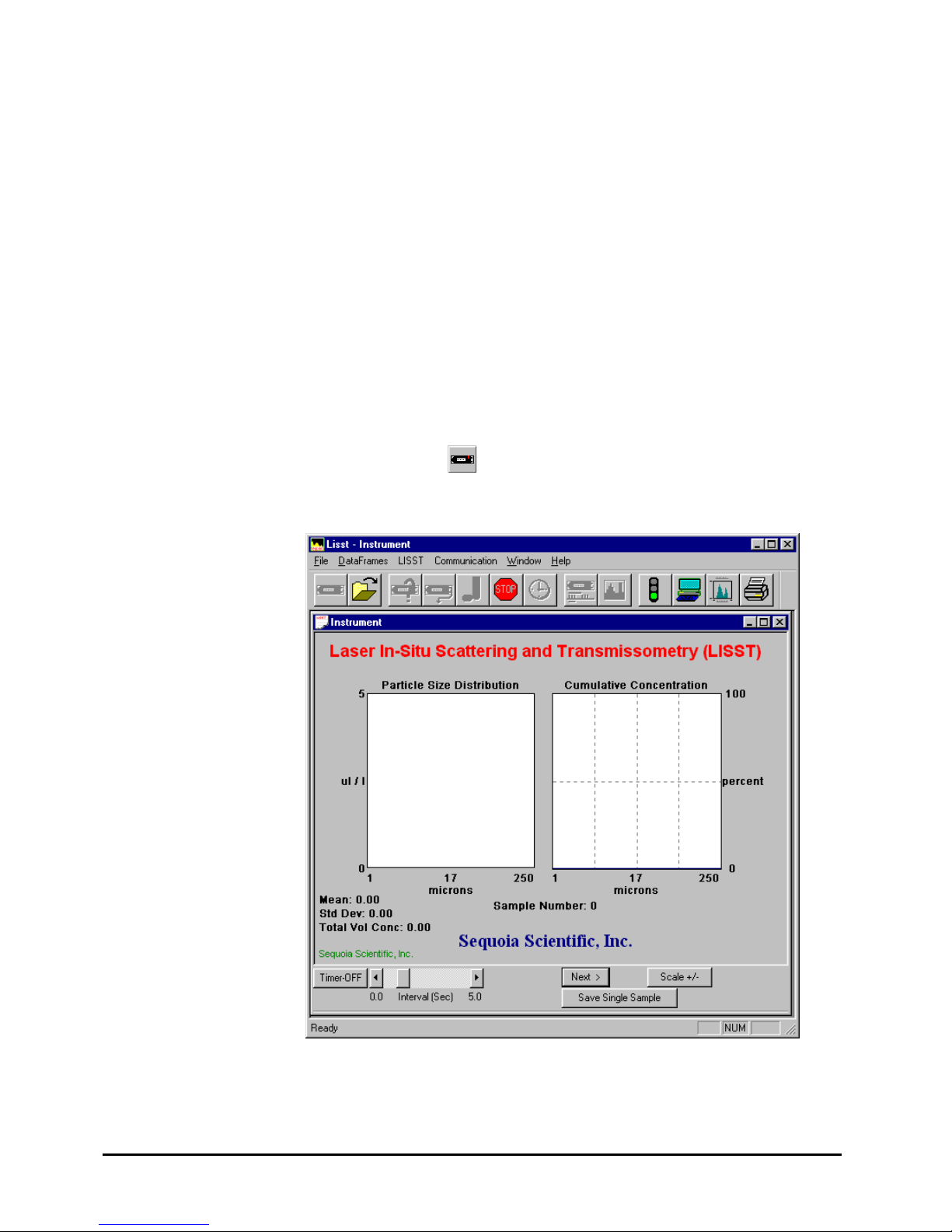
To open the Real-Time session, choose Open Real-Time Session from the
File menu or press the button. Choose a background file to use when
processing the data. Choose an output PSD file. A display very similar to
the View Processed datafile will be displayed.
Use the Timer button to start and stop data collection. The slider bar
controls the data acquisition time.
The Scale +/- Button adjusts the Particle Size Distribution scale. The
LISST – 100 User’s Guide 20
Page 25
Save Single Sample button records a single sample to an ASCII file.
Note: The main power and laser will be on until this window is closed or
until the Stop button is pressed. Significant loss of battery life can occur
if the instrument is left powered up for an extended period of time.
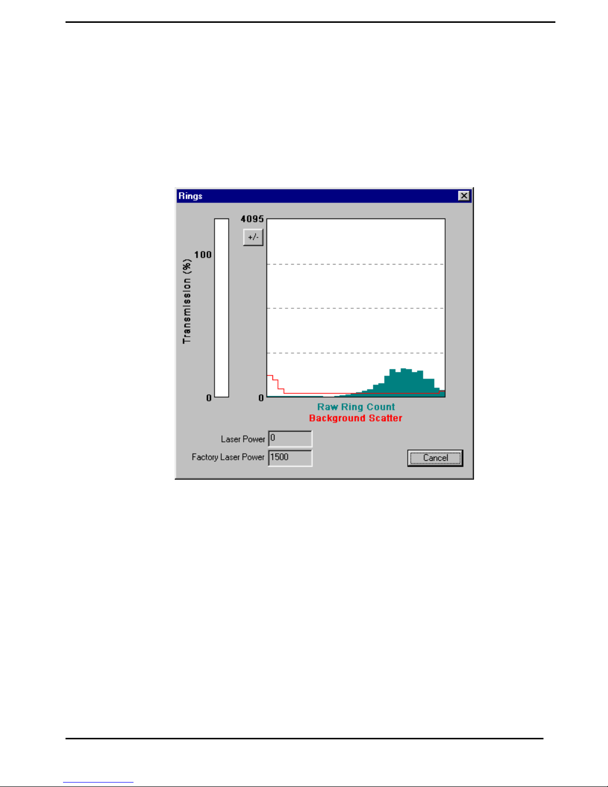
The Auxiliary Parameters window can be opened during the Real-Time
session so that the values of various parameters such as depth and
transmission can be monitored. The raw scattering values on the detector
rings can also be viewed by selecting View Rings from the DataFrames
menu. A typical display is shown below.
The view rings display is also available when processing a Raw Data file.
However, it is not available when viewing a processed Size Distribution
file.
21 LISST – 100X User’s Guide
Page 26

Step 22: Put
instrument back to
sleep
After finishing with the instrument it should be put back into its low
power sleep mode. In this mode, with the communication cable
disconnected, the drain on the battery is only about 0.08 ma. The sleep
mode can be used for extended periods. However, it is recommended that
for long term storage that the Main battery be disconnected.
To put the instrument in to low power sleep mode choose Put LISST to
Sleep from the LISST menu. There are also two new buttons on the
toolbar for putting the instrument to sleep and waking it up. To get the
lowest power consumption the Communications cable must be
disconnected from the instrument.
The above steps are meant to give a brief introduction to most of the
procedures that are required to operate the LISST-100X. Most of these
steps are covered in detailed Step-by-Step instructions in the following
sections.
LISST – 100 User’s Guide 22
Page 27

Step by Step procedures
The following topics are covered with Step by Step instructions.
Recording and
storing a
Background
Scatterfile
Downloading raw
data files and
Deleting Raw files
Recording a background scatter file is the first step in acquiring
data. This step-by-step describes the proper procedure to record
and download a background scatter file and save it for later
processing. Information on interpreting the Background Scatter
file is also provided.
Each data collection sequence is stored to a separate datafile on
the compact flash memory. Files can be offoaded to the PC using
the Download data function of the LISST-SOP software. After
downloading the data files can be deleted from memory. This step-
by-step procedure covers offloading and deleting files.
Process raw data
View Particle
size data
Process data in
Real-time
Configuring
Data Collection
Data that has been downloaded from the datalogger is in a raw
binary file. It must be processed into particle size by the LISST-
SOP program. the processing steps including optional displays and
procedures.
After processing of the data into a Particle Size Distribution
(PSD) file the data can be viewed to the screen. This step-by-step
procedure covers the viewing of data and optional displays.
Real-time processing of data requires configuring the datalogger
to output the raw information to the LISST-SOP program. This
step-by-step procedure covers the acquisition and storage of
processed data.
The LISST-SOP software allows the user to program the
instrument with a number of start and stop conditions. This step-
by-step procedure list the available options and the unique features
of each.
23 LISST – 100X User’s Guide
Page 28
STEP BY STEP PROCEDURE: RECORD AND STORE BACKGROUND SCATTERFILE
Step Action Result
1
2
3
• Clean instrument and install Horizontal test chamber.
• Fill with clean filtered water
• Connect communications cable and run LISST-SOP
software.
• If the data acquisition program is still running, stop
its execution with a <CTRL-C>.
• Open the Collect Background Scatter Data from
the LISST menu or by pressing the button on
the toolbar. After selecting the factory background
scatter file to use for comparison the window will
be displayed.
Optics submerged in water
Communications program
started.
L100X> prompt showing
Background collected and
saved.
When the BEGIN Collect button is pressed 20 samples
will be displayed to the screen as they are acquired.
After all 20 are collected the average will be
displayed. If the values are acceptable the values can
be saved to a file. Enter the filename in the box and
press the Accept and Save button.
LISST – 100 User’s Guide 24
Page 29

4
Notes:
• If there is a problem with the instrument or if the
water or windows are not clean, error messages will
be displayed. Dirty water or windows will generally
cause higher values across the middle rings. Large
bubbles or particles in the water can cause higher
values on the inner rings or left hand side of the
display. High values on the inner rings combined
with a lower Laser power value can also be an
indication of optical misalignment.
25 LISST – 100X User’s Guide
Page 30
STEP BY STEP PROCEDURE: OFFLOADING/DELETING DATA FILES
Step Action Result
1
2
3
• Start LISST-SOP program
• Select Offload from the LISST menu or press on the
Offload button.
• Choose the files to be offloaded by clicking on the
file name on the list. Multiple files can be selected
by hold down the CTRL key while clicking on files.
Use the SHIFT key to select a range of files.
Program started.
Gets current directory of files
from memory and displays the
list.
Files selected and path set.
• Press the OK button to accept the current selection.
A dialog box with a path for storing the downloaded
data will appear. Edit the path or press on the
Browse button to select a new path. The files names
will remain the same as on the compact flash. The
file creation date and time will not be preserved.
Press OK to begin the offloading.
LISST – 100 User’s Guide 26
Page 31

4
5
• A Status bar will be displayed for each file offloaded.
Text in the lower left corner will display the current
file being offloaded.
Deleting Files from memory
• After a file has been offloaded from memory is can
be deleted from the compact flash memory.
• Open the Terminal window by choosing Terminal
Window from the Communication menu or by
pressing on the Terminal Window button.
• At the Terminal Window enter the command DD in
the command box and press the send button. The DD
command (Display Directory) will list all the files in
memory to the screen.
• To delete a file enter the command DL filename.ext
where filename.ext is the file to offload. Wildcards
such as *.* or L*.dat can also be used.
WARNING: Once a file has been deleted there is no way
to recover the data. Make sure that the file has been
properly offloaded before deleting any files.
Offloading files from memory
to the PC
27 LISST – 100X User’s Guide
Page 32
STEP BY STEP PROCEDURE: PROCESSING RAW DATA
Step Action Result
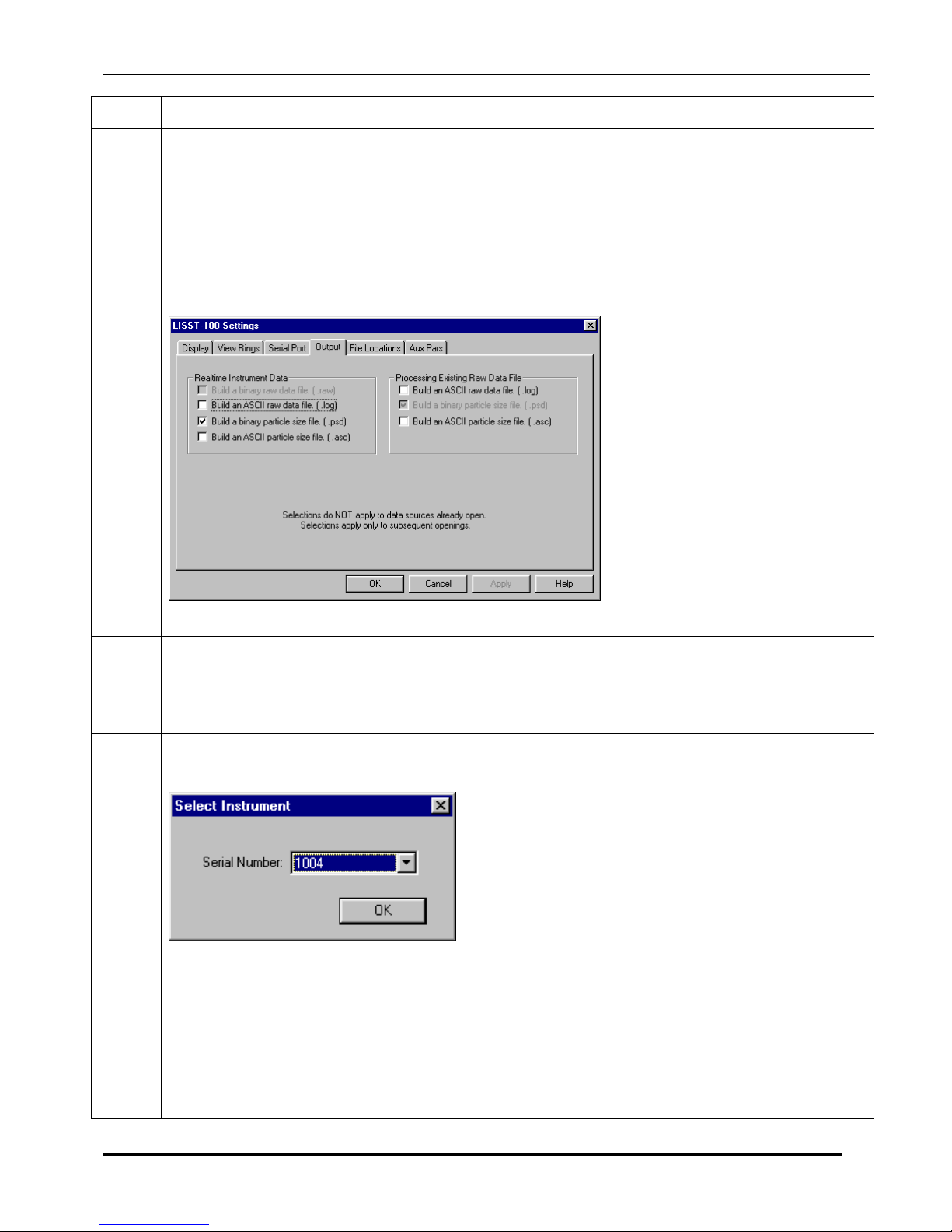
1
• Start LISST-SOP program
• Select Settings from the File menu and click on the
Output Tab. The window below will appear
prompting for the desired output to use for the future
data processing. Note: this selection must be made
BEFORE starting the processing command.
Program started.
Note: A binary PSD file is
always created when
processing raw data. This is
used to display the processed
data to the screen.
The ASC type is a spaced
delimited file containing all
the processed data.
The LOG file is a space
delimited file containing the
raw data from the datalogger.
2
3
4
• Select Open Raw Data File from the File menu
• Choose the serial number of the instrument that
collected the data to be processed.
Only the serial numbers of the instruments loaded into
the InstrumentData.Txt file and have the calibration
values loaded into the LISST.INI file in the Windows
directory can be used.
• Select the background scatter data file from the file
selection window. Double click the file or type the
file name and press Open.
Begins process of specifying
raw data file and all
information needed for data
processing.
Instrument serial number
selected.
Background scatterfile
selected.
LISST – 100 User’s Guide 28
Page 33
5
6
• Select the output data file name. The default file
name shown is the same as the raw data name but
with a different extension. You can change this name
if you wish. Provide the file name and press Save. If
other output types are selected they will have the
same base name with different extensions. Note: file
types other than the default PSD file must have been
selected before starting the Open Raw Data file
command. See step 1.
• A display similar to the one shown below will
appear.
Output data file name
selected.
Main data processing
selection window displayed to
the screen.
• The top portion of the display is a graphical
representation of the raw data from the 32 rings. The
value of the 32 rings is represented as a vertical line
with time moving from left to right.
• The lower portion of the display shows the time
history of some of the Auxiliary parameters. This
can be useful for determining when the instrument
came out of the water, when a particular profile was
started, or for determining what range of the datafile
to process. To change which Auxiliary parameters
are displayed, choose Auxiliary Parameter Display
from the Options menu.
• Note that only 400 samples of the Auxiliary
Parameters are displayed at a time. Use the Next and
Previous buttons to move through the complete
datafile. The triangles on the lower edge of the upper
display will indicate where in the complete datafile
the currently displayed section is located.
• The vertical cursor on the lower plot can be moved
by clicking the mouse at the desired location.
29 LISST – 100X User’s Guide
Page 34
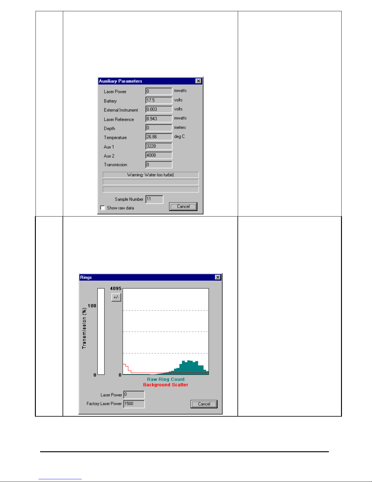
7
• Additional information is stored in the processed
datafile. The Auxiliary parameter window displays
these values for the current sample pointed to by the
vertical cursor. They will update as the cursor is
moved. Selecting the Show Auxiliary Parameter
Frame from the DataFrames menu opens the window.
An example of this window is shown below.
Auxiliary parameter window
displayed.
8
• The raw scattering values can be graphically
displayed by selecting the View Rings command
from the DataFrames menu. An example of this
display is shown below. As with the Auxiliary
Parameters, the vertical cursor indicates the sample
currently displayed.
Value of rings for current
frame displayed.
LISST – 100 User’s Guide 30
Page 35

9 To select the range of raw data to process position the
cursor at the desired starting sample. The display at the
lower portion of the screen will show the current sample
or frame. Pressing the Select First button will set the
current cursor position as the starting point for
processing. Similarly selecting Select Last will set the
end point for processing. Use the Next and Previous
buttons scroll through the complete datafile. The Select
First and Select Last points do not need to be on the
same displayed plot.
10 After selecting the range to process press the Process
File button. The display will show the processing
progress and the Process File button text will change to
Finished when the processing is complete. The window
can now be closed.
Notes:
Range to process selected.
Processing Completed
31 LISST – 100X User’s Guide
Page 36
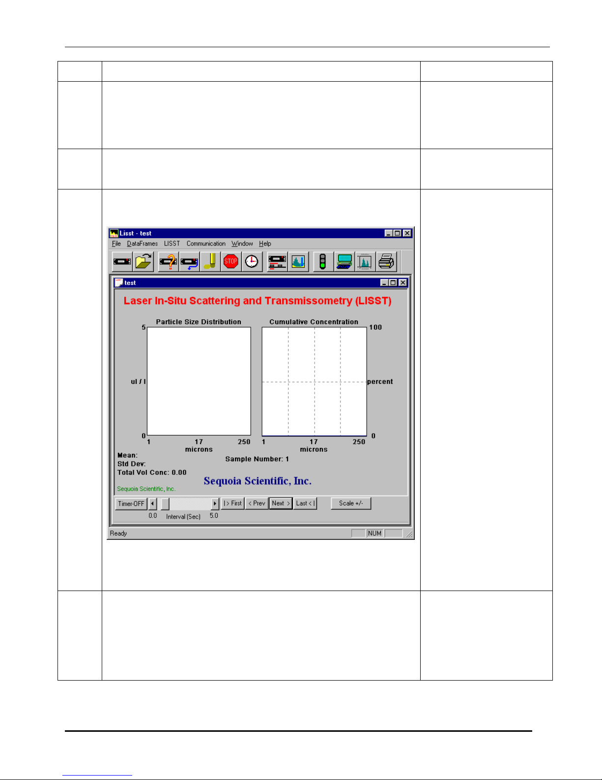
STEP BY STEP PROCEDURE: VIEW PROCESSED DATAFILE
Step Action Result
1
2
3
• Start LISST-SOP program
• Select Open Particle Distribution File from the File menu.
• Select the processed data file from the file selection window.
Double click the file or type the file name and press Open.
• After selecting the processed file a window similar to the one
shown below will appear.
Program started.
Open Particle
Distribution File
selected.
Processed datafile
selected.
• The left hand display is the volume distribution in units of
micro-liters/liter in each size class. The right hand display is
the Cumulative Concentration.
4
• Only a single sample is displayed at a time. By using the
buttons on the bottom of the display it is possible to
manually or automatically step through the datafile. The
Timer button will step through the datafile by updating the
display at a fixed rate. The rate is set by the slider bar next to
the Timer button.
LISST – 100 User’s Guide 32
Page 37
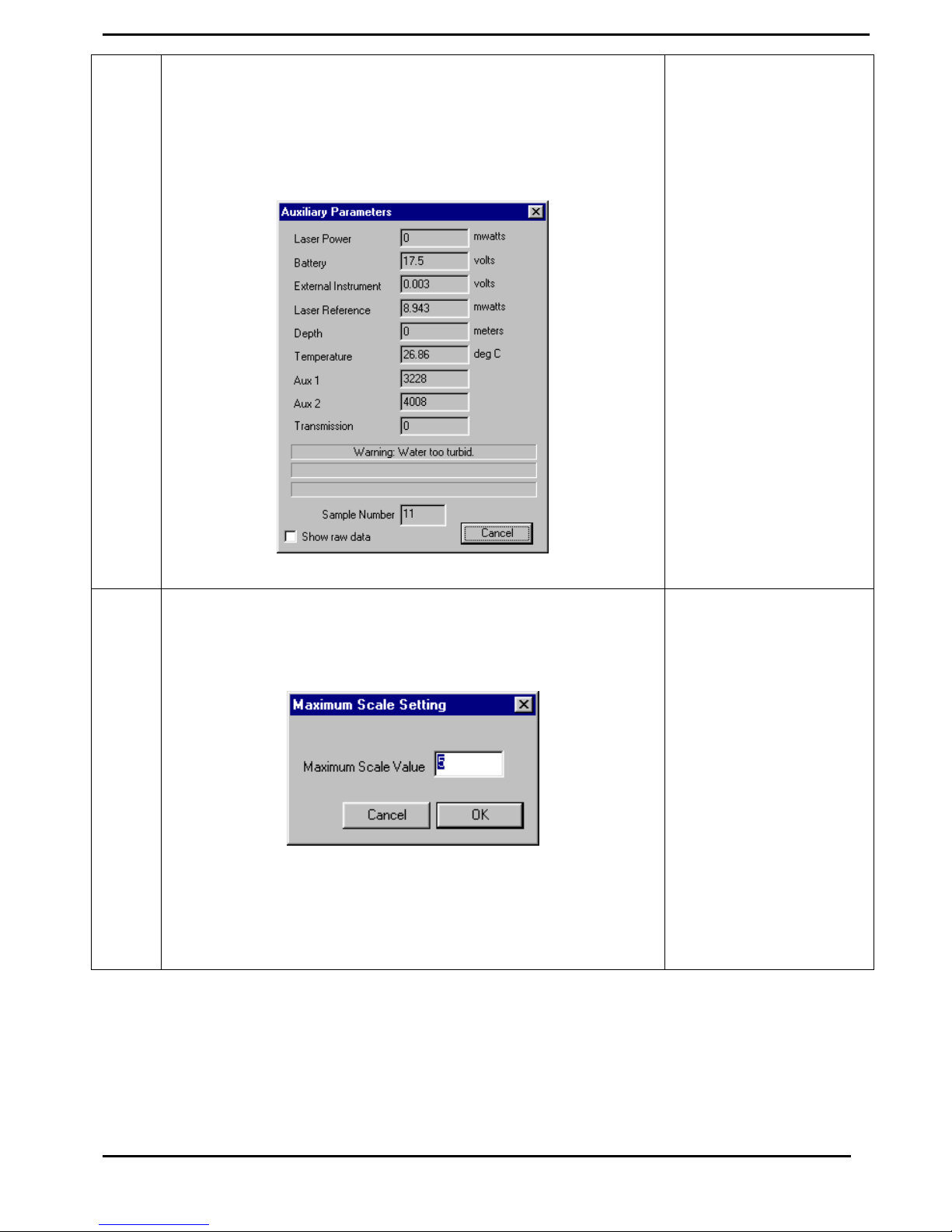
5
• Additional information is stored in the processed datafile.
The Auxiliary parameter window displays these values for
the current sample. They will update as the Volume
distribution is changed. The window is opened by selecting
Show Auxiliary Parameters Frame from the DataFrames
menu. An example of this window is shown below.
6
• The scale of the Volume Distribution plot can be changed by
using the Scale +/- button. After selecting the button a
display similar to the one shown below will prompt you for
the maximum concentration for the Y-axis of the plot.
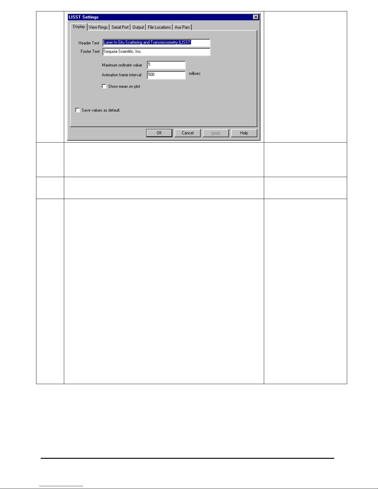
• Other options are also available for customizing the display
such as changing the header and footer text or adding lines to
show the mean and standard deviation. These features are
located on the Display tab of the Settings window as shown
below.
Display setting
modified.
33 LISST – 100X User’s Guide
Page 38
7
• The current display can be sent to the printer by choosing
Print from the File menu.
• Print Preview and Print Setup are also available.
Display printed.
8
• When finished viewing the processed data close the window
Notes:
Viewing of data
.
complete.
LISST – 100 User’s Guide 34
Page 39
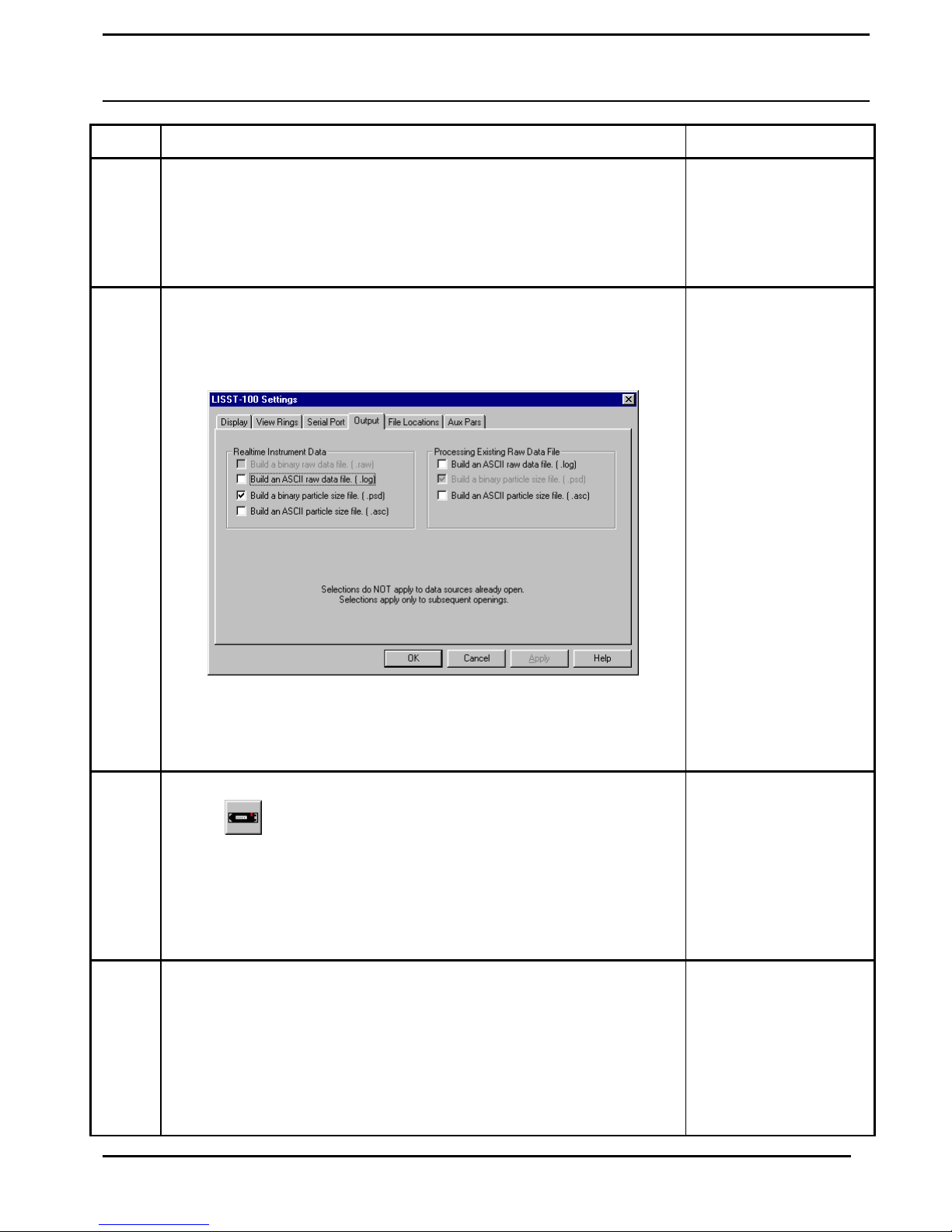
STEP BY STEP PROCEDURE: REAL-TIME DATA PROCESSING
Step Action Result
1
2
• Connect the instrument to the PC and start the LISST-SOP
program.
• Open the Operating Modes Window and choose the Real-Time
Operating Mode.
• Before starting a Real-Time session the output file options must
be set. This must be done before selecting Open Real-Time
Session. Select Output from the Options menu. The window
below will appear.
Instrument
configured for
Real-Time data
collection.
Output file type
selected.
Note: A binary
PSD file must be
selected before any
other file type will
be stored. This is
used to display the
processed data to
the screen.
The ASC type is a
spaced delimited
file containing all
the processed data.
3
4
• Select Open Real-Time Session from the File menu or press on
the
button.
• Choose the correct Background Scatter File and Select an
Output file.
• A display will appear on the screen. It is similar to the main
window of the View Processed Data function.
• By selecting the Next button the window will be updated with
the current size distribution. Note that if the water is clean the
display may not show any volume distribution. The Sample
Number value displayed underneath the plots will increment
each time a sample is saved.
The LOG file is a
space delimited file
containing the raw
data from the
datalogger
Open Instrument
selected.
Background and
Output file selected.
Sample saved.
35 LISST – 100X User’s Guide
Page 40
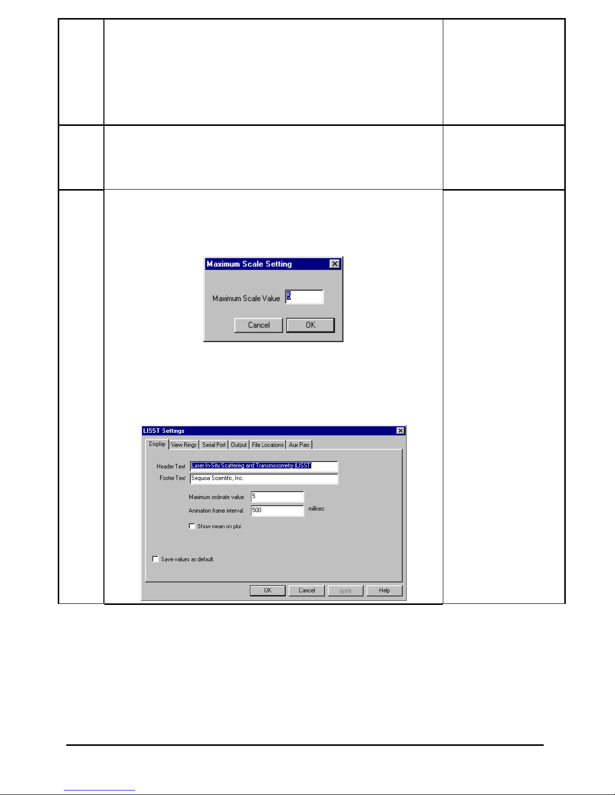
5
• The Timer button function is similar to its use in viewing
processed data. The timer will automatically acquire data at a
fixed rate. Note that this rate is limited to about 1 Hz due to the
processing of the raw data into Volume distributions. The slide
button next to the Timer button controls the sample speed. If it
is set too fast it will automatically reset to the maximum
allowed rate.
Timer button
pressed and
samples updating
automatically.
6
7
• The Auxiliary parameter window can be opened to display the
current values of the auxiliary parameters such as pressure and
temperature. Open the window by selecting the Show Auxiliary
Parameter Frame from the DataFrames menu.
• The scale of the Volume Distribution plot can be changed by
using the Scale +/- button. After selecting the button a display
similar to the one shown below will prompt you for the
maximum concentration for the Y-axis of the plot.
• Other options are also available for customizing the display
such as changing the header and footer text or adding lines to
show the mean and standard deviation. These features are
located on the Display tab of the Settings window as shown
below.
Auxiliary Parameter
window opened.
Display setting
modified.
LISST – 100 User’s Guide 36
Page 41

8
• The raw scattering values can be graphically display by
selecting the View Rings command from the File menu. An
example of this display is shown below.
Value of rings for
current frame
displayed.
9
• A single sample may be saved to a separate file by pressing the
Save Single Sample button
Averaged data
acquired and stored
to an ASCII file.
10
• When finished, close the main window to stop communication
with the LISST-100X.
Finished and
shutdown.
CAUTION: The laser and Main power are on continuously while in
the Real-Time Session. The program will stop and the power will
be turned off when the window is closed. However, if the window
is left open the power will remain on, potentially draining
substantial life from the battery. To turn off the power without
exiting the Real-Time session, press on
button on the toolbar.
To start data collection again press the Next button. The instrument
will power up and store a sample. This will take more time that a
normal sample. Once powered up the instrument will perform as
usual.
37 LISST – 100X User’s Guide
Page 42
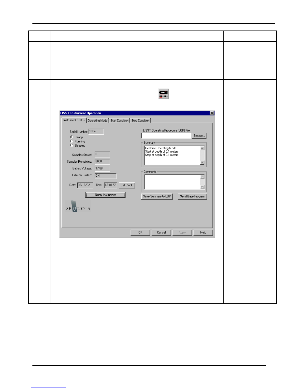
STEP BY STEP PROCEDURE: CONFIGURING DATA COLLECTION
Step Action Result
1
2
• Connect the instrument to the PC and start the LISST-SOP
program.
• Open the Operating Modes window by choosing Operating Modes
from the LISST menu or by pressing the
button on the
toolbar.
LISST-SOP open
and
communicating
with LISST100X.
Instrument Status
Displayed.
When first opening the Operating Modes window the LISST-SOP
program will send a Ctrl-C to the LISST-100X. If a program is
running it will be stopped. This is required so that the LISST-SOP
program can get the status information from the LISST-100X.
To set the LISST-100X data logger clock to the computer clock press
the Set Clock button. Press the Query Instrument button to refresh the
display.
Clock set
LISST – 100 User’s Guide 38
Page 43
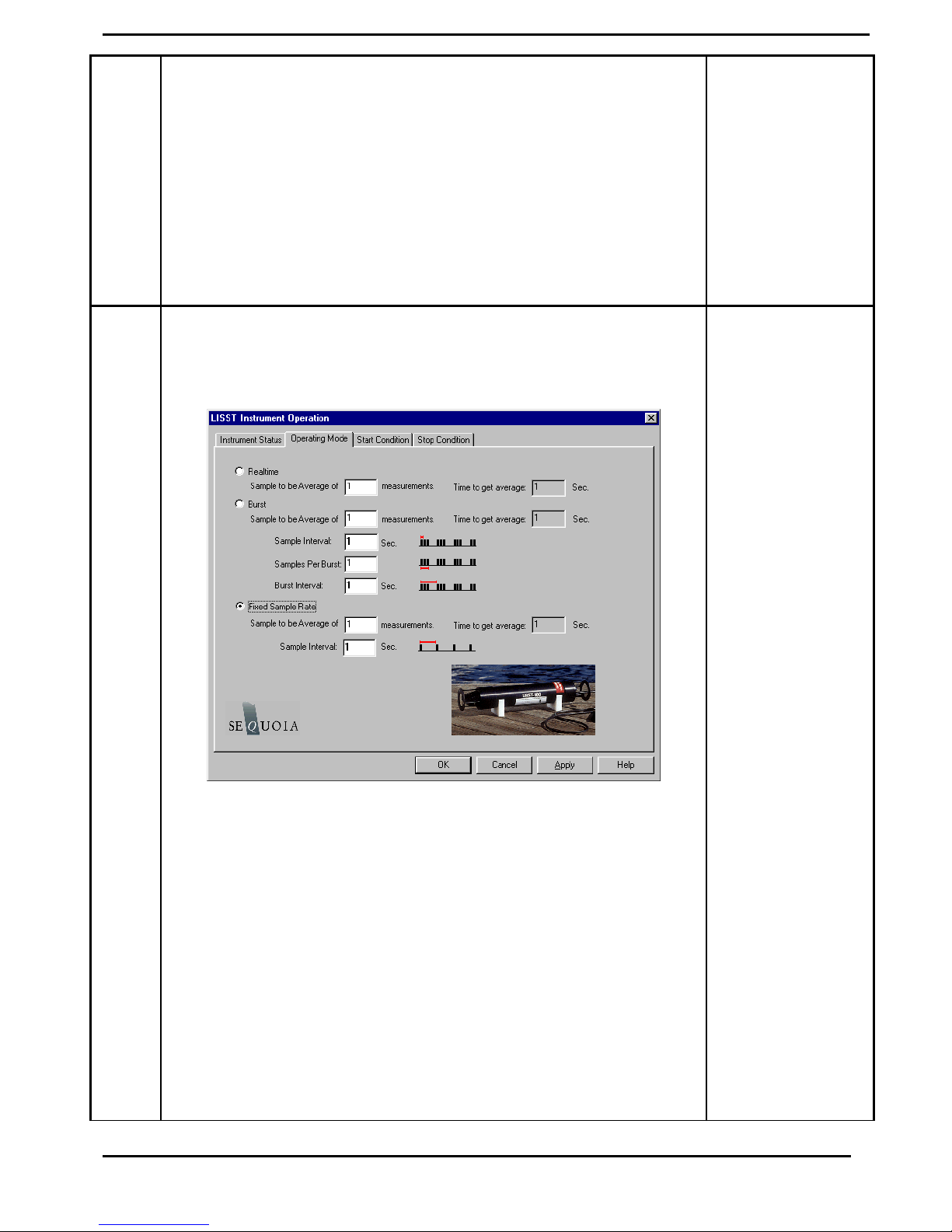
3
4
• To load a pre-saved LISST Operating Procedure file (LOP) enter
the file name in the file box or click on the Browse button to
navigate to the correct file.
• After the file is selected the appropriate settings will be made. To
apply these settings to the instrument press the Apply or OK
buttons.
LISST Operating Procedure files can be saved by clicking the Save
Summary to LOP button. The setting must have first been sent to the
instrument using the Apply button. The Summary section will only
update after the settings have been applied to the instrument.
• By selecting the Operating Mode Tab at the top of the main
window the screen below appears. This screen is used to set the
type of sampling; RealTime, Burst, or Continuous. You can also
select the samples per average and sample rates on this screen.
Operating Mode
set
• The RealTime mode is used for real-time size distribution
displays. This mode sends the raw data to the LISST-SOP
software for conversion to Size Distribution and displaying on the
screen. No data is saved in the datafile.
• The Burst and Continuous modes are used to save data in the on-
board datafile. The icons next to the various values give a better
understanding of their meaning. The software automatically
checks the values entered to make sure that there is no conflict.
For example, when a Samples per Average value is entered, the
minimum sample interval is computed. If this value is less than
the minimum permitted the value will be changed to the minimum
and the text will turn red. A similar test is done on the Burst
Interval setting.
39 LISST – 100X User’s Guide
Page 44
5
• Select Start Conditions tab to configure when the instrument will
begin sampling.
• There are five options: Depth, Time, External Mechanical Switch,
External Digital Input, and Time Delay. Select the mode by
clicking on the button next to the its label. Select the correct
parameters as required.
.
LISST – 100 User’s Guide 40
Page 45
6
• Choose the Stop Conditions Tab to select the conditions when
sampling should stop.
• The available stop conditions are: Depth, Time. External
Mechanical Switch, External Digital Input, Fixed number of
samples, and Maximum Memory or Low Battery.
.
• If the Stop Condition is either Depth, External Mechanical Switch,
or External Digital Input and the Start Condition is also one of
these three option the Base Program on the instrument will return
to waiting for the Start condition. For example, if the start and
stop conditions were set to External Mechanical Switch then
multiple sampling sessions can be obtained by flipping the switch
on and off. This is useful when doing profiles. It eliminates the
need to communicate with the instrument between profiles.
41 LISST – 100X User’s Guide
Page 46

7
• Select Apply or OK buttons to configure the instrument with the
current settings. If the Apply button is pressed the program will
return to the current window. Returning to the Instrument Status
window will display a summary of the current settings.
• If the OK button is pressed, when the configuration is complete
the user will be prompted to open the Terminal window to start the
program. The program on the instrument is configured but not
running. To start the program and have it start looking for the
Start conditions press the Run button on the Terminal window.
The Run button is equivalent to typing RUN and pressing Enter
from any terminal program.
• The Base Program will display text to the screen as it is running to
confirm that it is running and to indicate where it is in the
sampling cycle. Once the program is confirmed to be running and
waiting for the correct start conditions, the LISST-SOP program
can be closed and the communications cable can be disconnected.
Be sure to replace the connector cap before deployment.
.
LISST – 100 User’s Guide 42
Page 47

Instrument Communication
Serial Port
Settings
Using the
Terminal Window
Communication with the LISST-100X is via an RS-232C link. A
cable that connects the instrument to a PC has been provided.
This cable connects the 4-pin underwater connector on the
instrument to a DB-9 serial port connector. If required, DB-9 to
DB-25 pin adapters are available.
The RS232 link communicates at 9600 baud, 8 data bits, No
parity, and 1 stop bit. Data file transfer is done using a YMODEM
transfer at 115K baud.
Opening the Terminal Window, or alternate terminal software,
with the proper COM port and communications settings will allow
the user to communicate with the instrument. The LISST-100X
should respond by either displaying text from a running program
or echoing an L100X> prompt. If the instrument is in the Deep
Sleep Mode it will only wake up every 30 seconds, Print ZZZ to
the screen and then return to sleep.
Two Letter
commands
The instrument firmware is retained in on-board flash memory and
will start executing when power is applied. After a power up,
pressing the ENTER key will cause an echo of the L100X>
prompt. The Stop button will also send the commands to turn off
the main power to the laser and electronics. Pressing the Stop
button when the instrument is not running will not hurt the
instrument. It is recommended to press the Stop button multiple
times after stopping a running program to make sure that the main
power is properly shut off. Pressing the Start button will begin
the collection of data using the current configuration.
Under most situations the LISST-SOP will be used to configure
and operate the LISST-100X. However, there are times when the
LISST-100X must interface to another datalogger or custom
program. For this purpose a set of two letter commands is
available to operate the instrument. See the following section for
detailed descriptions of each command.
43 LISST – 100X User’s Guide
Page 48

Start Condition
The LISST-SOP software or two letter commands can configure
the LISST-100X with one of five Start conditions: Depth, Time,
External Mechanical Switch, External Digital Input, and Time
Delay. The details of each condition are described below.
Depth Start: The built-in depth sensor of the LISST-100X is used
to check the current depth to determine if the desired start depth
has been exceeded. The instrument is powered up and 5
measurements of the depth are averaged over a two-second period.
If the depth exceeds the threshold the program will proceed to the
data collection routine. If the depth does not exceed the threshold
the instrument will power down and wait 28 seconds before
checking the depth again. The program will continue checking
until the depth is exceeded or until the program is stopped.
Time Start: The program will check the current time every
second and compare it to the Start Time. If the Start Time is equal
to or earlier than the current time the program will go directly to
the data collection routine. It will continue checking the time until
the Start Time is reached or until the program is stopped.
External Mechanical Switch Start: The LISST-100X has a white
plastic lever on the endcap. This lever has a magnet imbedded in
it. This magnet can activate a switch inside the pressure case. The
base program looks at the status of this switch once a second. If
the switch is in the on or “1” positions the program will go directly
to the data collection routine. It will continue checking the switch
status until the switch is moved to the “0” position or until the
program is stopped. When in the “0” position the lever is up
against the zinc anode.
Data Collection
Routine
External Digital Input Start: The LISST-100X is equipped with
auxiliary inputs on the 6-pin underwater connector. Pin 2 of the 6pin connector is the DIG 1 input. The program will check the
status of the digital input once a second. If the voltage at the DIG
1 input is greater than 2 volts (relative to Digital Ground, Pin1) the
program will go directly to the data collection routine. It will
continue checking the status of the digital input until voltage
exceeds 2 volts or until the program is stopped. WARNING: The
maximum input voltage on the digital inputs is 3.3 volts.
Time Delay Start: The time delay start condition will cause the
program to wait the specified number of seconds before
continuing on to the data collection routine.
The LISST-SOP software can configure the Base program with
one of six Stop conditions: Depth, Time. External Mechanical
Switch, External Digital Input, Fixed number of samples, and
Maximum Memory or Low Battery. The details of each condition
are described below.
LISST – 100 User’s Guide 44
Page 49

Stop Condition
The LISST-SOP software can configure the Base program with
one of six Stop conditions: Depth, Time. External Mechanical
Switch, External Digital Input, Fixed number of samples, and
Maximum Memory or Low Battery. When storing data in the
Fixed Sample Rate mode the Stop conditions are checked after
each averaged sample has been saved. When storing data in the
Burst mode the Stop conditions are only checked after a full Burst
has been completed. The Start and Stop conditions have no effect
on the Real-time sampling mode. The details of each condition are
described below.
Depth Stop: The built-in depth sensor of the LISST-100X is used
to check the current depth to determine if it is less than the desired
Stop depth. The averaged depth from the last sample acquired is
used as the current depth. If the depth is less than the threshold the
sampling will stop. If the depth is not less than the threshold the
program will continue sampling as per the configuration. If the
Start Condition is a Depth Start the program will wait 30 seconds
and then return to looking for the Depth Start Conditions. The
delay is to keep the instrument from starting and stopping too
quickly as the instrument is moving up and down. If the Start
Condition is Depth Start the Base program will return to checking
for the Start Conditions. For all other Start Conditions the when
the current depth is less than the threshold the program will stop
and return to the L100X> prompt.
Time Stop: The program will check the current time after each
sample or burst and compare it to the Start Time. If the Start Time
is equal to or later than the current time the program will stop and
return to the L100X> prompt.
External Mechanical Switch Stop: After each sample or burst
the status of the Switch lever is checked. If the switch lever is in
the off or “0” position sampling will stop. If the Start Condition is
a Switch Start the program will return to checking the start
condition. For all other Start conditions the program will stop and
return to the L100X> prompt.
External Digital Input Stop: The status of the Dig 1 input is
checked after each sample or burst. If the voltage at the input is
less than 0.7 volts the sampling will stop. If the Start Condition is
a Digital Input Start the program will return to checking the start
condition. For all other Start conditions the program will stop and
return to the L100X> prompt.
Fixed Number of Samples: The program will acquire a fixed
number of samples before stopping. For the Fixed Sample Rate
mode the number of samples saved is checked after each sample is
saved. In the Burst mode the number of samples is checked only
after each burst. Therefore it may be possible to save more
samples than specified. When the number of sample to be saved
45 LISST – 100X User’s Guide
Page 50

has been reached the program will stop and return to the L100X>
prompt.
Maximum Memory or Low Battery: The Maximu m Memory o r
Low Battery Stop condition will continue to sample until the
memory capacity has been reached or when the battery voltage has
dropped to less than 6 volts. The program will continue to sample
until one of these conditions is met. It will then return to the
L100X> prompt.
LISST – 100 User’s Guide 46
Page 51

LISST-100X Command Summary
Display Commands
DD Display current Disk Directory
DS Display current status information
DB Display Current Battery Voltage
HE Display general help messages and command list
Setup Commands
OM x Set Operating mode.
ST x Set Start Condition.
TD x Set Start Condition Data
SP x Set Stop Condition
PD x Set Stop Condition Data
SI x Set Sample interval
MA x Set samples per average equal to x
BI x Set Burst Interval
SC mm/dd/yy hh:mm:ss Set Clock with time and date, where mm=month,
dd=day, yy=year, hh=hour(24 format), mm=minute,
ss=seconds, Example: ST 01/05/2005 21:05:03
SB x Set Samples per Burst
Acquisition/Action Commands
DL filename Grab sample and transmit it
GO Start Data collection using current parameters
GX Grab sample and transmit it
YS YMODEM offload of file at 115K Baud
ZS Acquire 20 samples and transmit them.
ZZ Go into deep sleep mode (minimum power
47 LISST – 100X User’s Guide
Used by SOP Acquire Background.
consumption)
Page 52
LISST-100X Command Details
Display Commands
DB Display Battery Voltage
Syntax: DB or db
Description: The current battery voltage is displayed to the screen.
Example: input: DB
output: Current Battery voltage: 8.90 volts
DD Display Disk Directory
Syntax: DD or dd
Description: Display current disk directory in DOS type format. Includes total bytes used
and bytes available.
Example: input: DD
results: L100x:>dd
LISST-100X Disk Directory
Volume in drive C is NONAME
Volume Serial Number is 778B-155F
Directory of C:\
L040305_.BIN 4,136 03-05-04 6:30p
L183705.BIN 1,672 03-05-04 6:37p
2 file(s) 5,808 bytes 0 dir(s) 15,933,440 bytes
freeL100x:>
DS Display current status information
Syntax: DS or ds
Description: The instrument settings and status are displayed to the screen.
Example: input: DS
output:
LISST-100X Current Status and Settings
Serial number = 1004
Operating Mode: Burst Mode
Start Condition: Time Start at 03/10/04 09:22:00
Stop Condition: Fixed Number Stop at 1 samples
Measurements per Average: 10
Sample Interval: 1
Burst Interval: 1
Samples per Burst: 0
Battery Voltage is 8.90
Current Date/Time: Wednesday, March 10, 2004 10:18:49
input: DS 1
output:
LISST-100X Current Status and Settings
LISST – 100 User’s Guide 48
Page 53

SN = 1004
OM = 2
ST = 2
TD = 03/10/04 09:22:00
SP = 5
PD = 1
MA = 10
SI = 1
BI = 1
SB = 0
BB = 0
CT = 0
IC = 0
Current Time = 03/10/04 10:18:49
Battery = 890
Switch = 0
Memory= 15005640
HE Display general help messages and command list
Syntax: HE or he
Description: Displays the list of command to the screen.
Example: input: HE
output: LISST-100X Commands (followed by 30 lines of text)
Setup Commands
OM Set Operating Mode
Syntax: OM x or om x
Description: Sets the Operating Mode to one of the following types:
1 = Real Time Mode
2 = Burst Mode
3 = Fixed Rate Mode
OM command only without a parameter will initiate a prompt for the
Operating mode.
Example: input: OM 3
output:
49 LISST – 100X User’s Guide
Page 54

MA Set measurements per average
Syntax: MA x or ma x
Where x = number of samples per average
Description: Each recorded or displayed measurement is based on an average of
measurements. The number of measurements per average is set using the SA
command.
If no value follows command, prompts will be displayed for the value.
Example: input: MA 10
Cautions: None
ST Set Start Condition
Syntax: ST x or st x, where x is the start condition code:
Description: The ST command sets the start condition to be used when the GO command
is issued. The start condition options are:
1 = Depth Start
2 = Time/Date Start
3 = Mechanical Switch Start
4 = Digital Input Start
5 = Delay Start
If no value follows command, prompts will be displayed for the value.
Example: input: ST 5
TD Set Start Condition Data
Syntax: TD x or td x, where x is the start condition data :
Description: The TD command sets the start condition data to be used when the GO
command is issued. The start condition data is used with the Start Condition
setting. For example, if the Start Condition is Depth Start (option 1) the
input will be start depth in meters. If the start condition is set to Time/Date
Start (option 2) the input for TD will be the start date and time. If the Start
Condition is Delay Start (option 5) the input will be time delay in seconds.
The TD setting is ignored for Mechanical Switch Start (option 3) or Digital
Input Start(option 4).
If no value follows command, prompts will be displayed for the value.
Example: input: TD 12/31/05 23:59:59 or TD 3600
SP Set Stop Condition
Syntax: SP x or sp x, where x is the stop condition code:
Description: The SP command sets the stop condition to be used when collecting data.
The stop condition options are:
1 = Depth Stop
LISST – 100 User’s Guide 50
Page 55

2 = Time/Date Stop
3 = Mechanical Switch Stop
4 = Digital Input Stop
5 = Fixed Number of Samples Stop
6 = Maximum memory or Low Battery Stop
If no value follows command, prompts will be displayed for the value.
Example: input: SP 5
PD Set Start Condition Data
Syntax: PD x or pd x, where x is the start condition data :
Description: The PD command sets the start condition data to be used when the collection
data. The stop condition data is used with the Stop Condition setting. For
example, if the Stop Condition is Depth Stop (option 1) the input will be stop
depth in meters. If the stop condition is set to Time/Date Stop (option 2) the
input for TD will be the stop date and time. If the Stop Condition is Fixed
Number Stop (option 5) the input will be the number of samples to collect
before stopping. The TD setting is ignored for Mechanical Switch Stop
(option 3) or Digital Input Stop(option 4).
Example: input: PD 12/31/05 23:59:59 or PD 3600
SB Set Samples per Burst
Syntax: SB x or sb x where x is the number of samples per burst.
Each sample it taken at the sample interval set by the SI command.
If no value follows command, prompts will be displayed for the value.
Example: input: SB 10
SC Set Clock with time and date
Syntax: SC mm/dd/yy hh:mm:ss or st mm/dd/yy hh:mm:ss
Where mm=month, dd=day, yy=year, hh=hour(24 format),mm=minute,
ss=seconds
If no values follow the “SC” or “sc” command, prompts for entering the time
and date will be displayed.
Example: input: SC 01/05/2001 21:05:03
Acquisition/Action commands
DL Delete file from Compact Flash Module
Syntax: DL filename or dl filename where filename is the name of the file to be
deleted.
Description: DL command is used to delete file from the Compact flash module.
Wildcards such as *.* can be used.
51 LISST – 100X User’s Guide
Page 56
Example: Input: DL L159*.dat
Output: Are you sure (Y/N)…
Cautions: WARNING: Make sure that the file being delete has already been offloaded
before deleting the file. Once the file is delete it can not be recovered.
GO Start Data Collection using current Settings
Syntax: GO or go
Description: Starts Fixed Rate or Burst Mode Data collection using current settings.
Example: Input: GO
Output: Waiting for start conditions…
Cautions:
To stop acquisition before it is complete press the Stop button or CTRL-C.
GX Grab sample and transmit it
Syntax: GX or gx
Description: Acquires single averaged sample and displays the result to the screen.
Example: Input: GX
Output: {
…. 32 ring values + 8 Aux parameters
}
Notes: The GX command does not store the sample to a datafile.
YS YMODEM Offload
Syntax: YS filename or ys filename where filename is the name of the file to be
offloaded.
Description: Offloads file from Compact Flash Module to PC using YMODEM offload at
115 Kbaud
Example: Input: YS L1391205.dat
Output: Starting…
Notes: The YS will initiate the YMODEM offload on the instrument. A YMODEM
file transfer must be started on the PC to accept the data. HyperTerminal can
accept YMODEM file transfers at 115K baud.
ZS Grab 20 samples and transmit it
Syntax: ZS or zs
Description: Acquires 20 averaged sample and displays the result to the screen. The ZS
command is used by the LISST-SOP program when acquiring a background.
Example: Input: ZS
Output: {
…. 32 ring values + 8 Aux parameters
}
repeat 20 times
LISST – 100 User’s Guide 52
Page 57
Notes: The ZS command does not store the sample to a datafile.
ZZ Go into deep sleep mode (minimum power consumption)
Syntax: ZZ or zz
Description: Sends LISST-25X in to low power sleep mode. Instrument will wake up
every 10 seconds and wait for a response. If there is no response with in 2
seconds, the instrument will return to sleep mode.
Example: Input: ZZ
Output: Deep Sleep… Enter zz to wake up
Deep Sleep… Enter zz to wake up
Deep Sleep… Enter zz to wake up
Cautions: The background scattering data and other settings are not affected by the ZZ
command.
53 LISST – 100X User’s Guide
Page 58

Performance Optimization
Background
Scatterfile and its
Importance
This section contains information on optimizing the performance
of the LISST-100X.
As was discussed in earlier sections, the LISST-100X uses a
custom detector to measure light scattered at small angles from
particles in water. In order to measure only the scattered light
contributed by the particles, a measurement of the background
scattering must be obtained. This background scattering can
come from a number of areas. Scratches on the windows,
imperfections on the optics, and other sources all contribute to the
scattered light. By subtracting this background scattering from
the measured data, a true measurement of the light scattered from
the particles can be obtained. The measurement of background
scattering has come to be called a "ZSCAT". The name comes
from the fact that the measurement is obtained using water with
zero "scatterers" or particles.
It is very important that clean and bubble free water is used. The
water can be fresh or salt water. For most applications, it has
been found that steam-distilled water is sufficient. Steamdistilled water is typically available in one-gallon containers. We
have found that this distilled water tends to be a bit cleaner than
typical bottled or packaged water. We buy steam-distilled
drinking water and filter it through a 0.2μm filter.
Watch for
outgassing
Clean optics end
before acquiring a
background
Another consideration when acquiring a background is
"outgassing" causing small bubbles to form on the instrument and
windows. Bubbles on the windows will greatly modify the
scattering pattern, rendering the background useless. Be sure to
remove any bubbles from the windows before acquiring a
background scatterfile. Use a squirt bottle or pipette to blow the
bubbles off the window.
A small volume horizontal chamber has been provided for
submerging the optics while acquiring a background. It is
inserted between the windows of the optics, The instrument
should be placed horizontally on the supplied white plastic
supports. Roughly 120 milli-liters of water is needed to fill the
chamber.
Because the area surrounding the windows is submerged, it is
important to thoroughly clean and rinse this part of the instrument
before acquiring a background.
Toothbrush, liquid soap and water works well for cleaning
the optical end of the instrument; do not use abrasive
powders, they will scratch optics and destroy instrument
performance.
LISST – 100 User’s Guide 54
Page 59

Avoid Direct
sunlight
Direct sunlight should also be avoided when obtaining a
background. The unit is relatively insensitive to sunlight;
however, bright light can increase the noise in the measurement
and give a false background scattering measurement. It is
recommended that the end of the instrument be shrouded with a
dark cloth during the acquisition of the background. In general,
the background should be taken in conditions that match the
deployment conditions as closely as possible.
The low concentration limit of LISST-100X is very sensitive to
the quality of the background scatterfile. For this reason, when
working in near-surface or mid-depth water, it is very important
that a good background file be obtained with very clean water.
As particle concentrations increase, the relative signal-tobackground noise ratio also increases, thus reducing the
importance of the background. However, Background
Scatterfiles should always be done before an experiment.
Plastic bags, Tupperware or clean containers of any kind can be
used to acquire a background. The instrument’s optics end can be
submerged in them vertically, as long as the optics are completely
submerged and there is no blockage of the windows by bubbles
or other objects.
Backgrounds Scatterfiles should always be done before each
data collection.
55 LISST – 100X User’s Guide
Page 60

Optical Alignment
The background scatterfile is the best source of information on
the current health of the LISST-100X. It provides information on
the current functionality of all of the major systems including
laser, ring detector, data collection electronics, and optical
alignment. The LISST-100X is a sensitive optical device. The
laser must be aligned such that the focused spot is centered on the
hole in the center of the ring detector. If this alignment in not
correct the instrument will not function correctly. The
background file can easily provide the user with information
about the status of the alignment.
The first indicator of an alignment problem is a severe drop in the
transmitted laser power. The laser power and laser reference
values will change over time but they should track together. If
the laser power drops to less than 50% of the factory value,
without a corresponding drop in the laser reference value,
misalignment may be occurring.
The second indictor of misalignment is high value on the inner
rings. The inner rings are shown on the left side of the
background display. As the focused laser starts to move away
from the center of the ring detector it will scatter more light onto
the inner rings. This will cause the inner ring values to be much
higher than the factory values.
It must be noted that low laser power or high inner rings may not
always indicate misalignment. Low laser power can also occur
because the windows or water is dirty or if there are bubbles on
the window. Large particles or bubbles can cause the inner rings
to be higher than factory values. All of the other possibilities
must be eliminated before the conclusion of misalignment can be
reached.
The newest generation of transmit optics do allow for the
possibility of the user adjusting the alignment in the field. A
written procedure can be provided for this procedure. However,
it is highly recommended that the need for re-alignment be
discussed with a trained Sequoia Scientific technical service
representative before attempting this procedure.
LISST – 100 User’s Guide 56
Page 61

Instrument Mounting
Mount the
instrument
Horizontal
Isolate from all
other metal
This section contains information on mounting of the LISST100X.
The LISST-100X measures scattered light to obtain particle size
distributions. Therefore it is important to keep particles from
sticking to the window surface. The first line of defense it to
keep the window surface vertical by mount the instrument
horizontally. This is most critical when the water motion is slow.
When working rivers or towed application the orientation is not
as critical.
The center section of the main pressure case has a slightly smaller
diameter than the ends. The smaller diameter section is the
suggest mounting area. The U-shaped mounting block provided
with the instrument fit this diameter and can be used for
mounting the instrument.
To reduce the corrosion of the aluminum parts a zinc anode is
attached to the Connector endcap. This anode must be exposed to
the water for it to be effective.
When mounting the instrument be sure to electrically isolate the
instrument from all other metal. Any contact with other metal
can greatly increase the rate of corrosion. Isolate the instrument
with rubber or plastic to keep the LISST-100X from being the
sacrificial anode for the mounting hardware.
57 LISST – 100X User’s Guide
Page 62
Instrument Storage & Maintenance
Again it must be emphasized that the LISST-100X is a sensitive
instrument. When not in use, the instrument should be stored in a
well padded case. For longer storage (year or so), the
communication cable should be disconnected and the battery
pack should be disconnected or removed. If you do not wish to
remove the battery or disconnect it, battery life can be prolonged
with the use of the Low Power Sleep Mode. In this mode the
instrument will use no more than 10% of a typical battery life
over a 6 month duration.
To put the instrument in to low power sleep mode choose Put
LISST to Sleep from the LISST menu. To get the lowest power
consumption the Communications cable must be disconnected
from the instrument and the Switch Lever on the endcap must be
in the “1” position.
As has been noted earlier, the condition of the windows is critical
to the performance of the LISST-100X. Care must be taken when
cleaning the windows. The windows and the instrument should
be rinsed thoroughly with fresh water after each deployment.
The windows should be cleaned with a soft cloth or lens tissue.
Liquid detergent/soap and water may be used. For removing
grease spots, finger prints, etc, alcohol may be used. We
recommend against the use of stronger solvents such as Acetone
or Toluene.
Abrasive powders must never be used near the optics
windows, they will scratch the windows and degrade
instrument performance.
O-rings that seal the mating parts of the instrument must be
maintained and inspected regularly. Whenever the end cap is
removed, check the o-ring for any cuts or marks, and clean and
lightly grease the o-ring before installing the end cap. Spare end
cap o-rings have been provided. O-rings are inexpensive items
that provide an invaluable service; replace them if in any doubt
about their condition. When replacing the O-ring, be sure to
clean the O-ring groove thoroughly with cotton-swabs etc.
making sure that no fibers or particles of dirt are left after the
cleaning.
LISST – 100 User’s Guide 58
Continued on the next page...
Page 63

Maintenance Notes
Battery Power and
Access
The LISST-100X should not require any adjustment or
calibrations. The pressure and temperature sensors can be recalibrated if desired. The performance of the instrument can be
checked with the use of a sample of particles of a known size
distribution.
Comparison of the LISST-100X's performance with that of
other particle-size measuring devices that are not based on
laser diffraction may result in inconsistencies because the
instruments may measure different properties of the particles
to interpret particle size.
The main battery is mounted to the connector end cap. SEQUOIA
supplies the custom battery packs for use with the LISST-100X
instrument. The use of batteries other than these may void your
warranty. When using laboratory power supplies, the user must
exercise extreme caution in using correct polarities on the external
3-pin connector. Reverse polarities or misconnection may
damage the electronics, the repair of which would not be covered
under the warranty.
The step-by-step procedure for accessing and replacing the battery
pack is described below.
59 LISST – 100X User’s Guide
Page 64

STEP BY STEP PROCEDURE: CHANGING THE BATTERY
Step Action Result
1
• Place the LISST-100X in a horizontal position.
U-blocks have been provided for this purpose.
• Disconnect all cables from the end cap.
• Install caps on connectors to protect pins.
Caps MUST be installed on connectors before submerging into water.
2
• Remove the three recessed bolts from end cap.
Use the Allen wrench provided. The threads of the bolts have been
coated with an anti-seize compound. Spare bolts are included with
Caps installed on the
connectors.
The recessed bolts
removed from the
end cap.
the LISST-100X.
3
• Next, remove the end cap by grasping the ring attached to the end
cap with standoffs and pull away from the case. Slight rotation will
sometimes be helpful.
The end cap has an o-ring seal on the inside diameter of the case.
The compression of the o-ring seal contributes to the effort required
End cap and battery
removed from the
case.
to remove the end cap.
The end cap should remain parallel to the end of the case. Tipping
of the end cap can cause binding.
Do Not Pry the End Cap Off.
If the removing the endcap requires extensive effort threaded holes
next to the holddown screws have been provided to force the endcap
away from the case. Remove the screws from the case and insert
them into the threaded holes. Thread the screws in evenly until the
endcap is free. When the o-ring on the end cap clears the case, the
end cap and battery combination should slide easily from the case.
WARNING: The endcap and battery cable assembly will still be
connected to the main electronics. The assembly can only be
removed a few inches from the end of the pressure case.
To expose the battery and battery cable connectors, remove the
Velcro wrap.
Continued on the next page...
LISST – 100 User’s Guide 60
Page 65

4
• To remove the battery, release the Velcro wrap and loosen the nuts
on the threaded rods. Remove the plate. Do not remove the threaded
Battery removed and
replaced.
rods.
Before removing the battery, make note of its orientation so that the
replacement battery can be positioned similarly.
• With the new battery in place, tighten the nuts on the threaded rods
to finger tightness. Re-apply wrap allowing for access to the power
connectors.
Make sure that the battery does not overhang the edge of the end
cap diameter. If the battery is offset, the end cap may not seat
properly, making installation difficult.
5
• Re-Connect the white female 2-pin connector to the white male 2-
Power on.
pin connector. Connecting these connectors will apply power to the
electronics module. Once power is applied the instrument begin
running and the L100X> prompt will be displayed. It may be
necessary to put the instrument into low power sleep mode after the
battery is reconnected.
• Re-wrap the battery with the Velcro wrap. Adjust the position of
the connectors to minimize the diameter of the assembly. If the
connectors are not arrange properly it will be difficult to insert the
battery into the pressure case.
6
• Before installing the end cap into the case, clean and lightly grease
the o-ring.
• Remove the o-ring and inspect for any cuts or defects.
O-ring greased and
inspected for any
defects.
Use clean fingers to apply o-ring grease. Paper or cloth can leave
fibers on the o-ring which can cause the o-ring to leak. The inside
diameter of the case should be similarly cleaned and lightly greased.
7
• Install the end cap into the case by first lining up the holes in the end
cap with the threaded holes in the case.
• Applying uniform force, push the end cap into the case. After the
The end cap installed
into the case and the
case is now sealed.
end cap is inserted, slightly rotate the end cap.
A slight twisting motion will help the o-ring obtain a good seal. This
will also allow the bolt holes to be lined up.
• Install the bolts, tightening evenly, until they are snug but not tight.
Do not over tighten. The stainless steel screws can damage the
threads of the aluminum case if over tightened. The endcap has a
radial o-ring seal and is not dependent on the tightness of the screws
for sealing.
61 LISST – 100X User’s Guide
Page 66
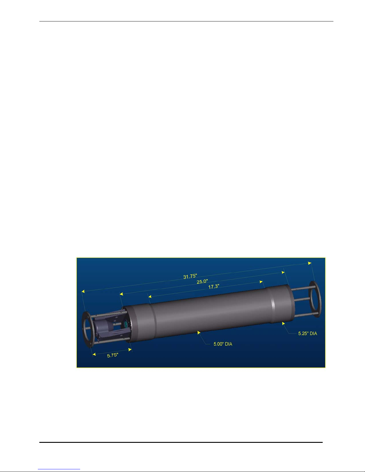
Technical Specifications
• Parameters measured/derived
Particle Size distribution
Total Volume Concentration
Optical Transmission
Depth
Temperature
• An external analog input (0-2.5V)
• Two external digital I/O ports (5V logic)
• Optical path length: 5 cm standard, 2.5 cm optional
• Optical transmission: 12 bit resolution
• Particle size range: Type B: 1.25 - 250 micron diameter, Type C: 2.5 –500 micron
• Resolution: 32 size classes, log-spaced
• Data storage memory: 128MB (1.6 million samples) standard, expandable to 1 GB
• Maximum sample speed: 1 size distributions per second (standard)
• Temperature-sensor range: -10 to 45oC resolution: 0.01
• Depth Sensor range: 0 to 300 m of H
• External power input: 12V nominal (6 to 15V)
• Dimensions: 13.33 cm (5.25") dia x 81 cm (32")
• Weight in air: 12 Kg (25 lb)
• Weight in water: 4 Kg (8.5 lb)
• Depth rating: 300 m (standard)
• Connector Endcap screws: Socket head cap screws #8-32 3/4” long
• Endcap O-ring: Parker Part # 2-244
o
C
O, resolution: 8 cm of H2O
2
LISST – 100 User’s Guide 62
Page 67
Appendix A: Instrument Specific Documentation
Instrument Model Number
Instrument Serial Number
Instrument Manufacture Date
Instrument Memory Capacity
Instrument Accessories
Instrument Owner
Auxiliary Parameters
The table below lists the auxiliary parameter labels and calibration constants. These values are saved
in the LISST.INI file. They can be viewed and/ or edited using the “Edit Calibration Constants” from
the DataFrames menu.
Auxiliary Parameter Display Label Multiplier Offset Units
Parameter 1 Laser Power mW
Parameter 2 Battery 0.01 0 volts
Parameter 3 External Instrument volts
Parameter 4 Laser Reference mW
Parameter 5 Depth 0.01 meters depth
Parameter 6 Temperature 0.01 0 Deg. C
Parameter 7 Day*100 + Hour 1 0
Parameter 8 Minutes*100 + seconds 1 0
Volume Conversion Constant
Constants for Firmware
These constants are entered at the factory to be resident in the instrument firmware.
Parameter Number Parameter Multiplier Offset
Parameter 1 Battery Volts
Parameter 2 Depth
Parameter 3 Temperature
Instrument Reference Data:
Ring Values 1 Laser Power (counts) =
1 – 5 2 Laser Reference Power (counts) =
(counts) 3
4
5 Verified by:
63 LISST – 100X User’s Guide
Page 68

Appendix B: Data Storage Format and Size Ranges
Size Ranges, Angles of Observation and Data Storage Format
Size Ranges
There are 32 size ranges logarithmically placed from 1.25 - 250
microns in diameter, or 2.5 – 500 microns (the upper size in each
bin is 1.180 times the lower).
The table below shows the median
size of each size class. For
clarity the table is shown with multiple rows. In the output data
file the data for each size class is oriented in one row from small
to large.
Type B Instruments – 1.25 to 250 micron size range
1.44 1.68 1.97 2.31 2.72 3.19 3.76 4.43
5.21 6.14 7.24 8.54 10.1 11.9 14.0 16.5
19.5 23.0 27.1 31.9 37.6 44.4 52.4 61.7
72.8 85.9 101 119 140 166 196 231
Type C Instruments – 2.50 to 500 micron size range
2.72 3.20 3.78 4.46 5.27 6.21 7.33 8.65
10.2 12.1 14.2 16.8 19.8 23.4 27.6 32.5
38.4 45.3 53.5 63.1 74.5 87.9 104 122
144 170 201 237 280 331 390 460
Angles
The median angles (in Degrees) for the VSF measurement are
shown in the table below.
Type B Instruments – 1.25 to 250 micron size range
0.106 0.125 0.148 0.174 0.206 0.243 0.287 0.338
0.40 0.47 0.56 0.66 0.77 0.91 1.08 1.27
1.50 1.77 2.09 2.46 2.91 3.43 4.05 4.78
5.64 6.65 7.85 9.26 10.93 12.90 15.22 17.96
Type C Instruments – 2.50 to 500 micron size range
0.053 0.063 0.074 0.087 0.103 0.121 0.143 0.169
0.20 0.24 0.28 0.33 0.39 0.46 0.54 0.64
0.75 0.89 1.04 1.23 1.45 1.72 2.02 2.39
2.82 3.33 3.93 4.63 5.47 6.45 7.61 8.98
Raw Data Storage
The values in the raw data file are stored in the order shown in
LISST – 100 User’s Guide 64
Page 69
Format
Elements Parameter
Processed Data
Storage Format
Elements Parameter
the table below.
1:32 Light intensity on detectors 1 through 32
33 Laser transmission Sensor
34 Battery voltage in raw counts
35 External Auxiliary input 1 (0 to 5V = 0 to 4096)
36 Laser Reference sensor
37 Pressure in raw counts
38 Temperature in units of 100ths of degrees C
39 (Day*100 + Hour) at which data taken
40 (Minutes*100 + Seconds) at which data taken
The values in the processed data file are stored in the order
shown in the table below. Each sample is stored in one row.
1:32 Volume concentration (in ul/l) for size class 1
through 32
33 Laser transmission Sensor
34 Battery voltage in calibrated units
35 External Auxiliary input 1 in calibrated units
36 Laser Reference sensor in calibrated units
37 Pressure in calibrated units
38 Temperature in calibrated units of degrees C
39 (Day*100 + Hour) at which data taken
40 (Minutes*100 + Seconds) at which data taken
41 Computed % Optical transmission over path
42 Computed Beam-C in units of 1/m
65 LISST – 100X User’s Guide
Page 70
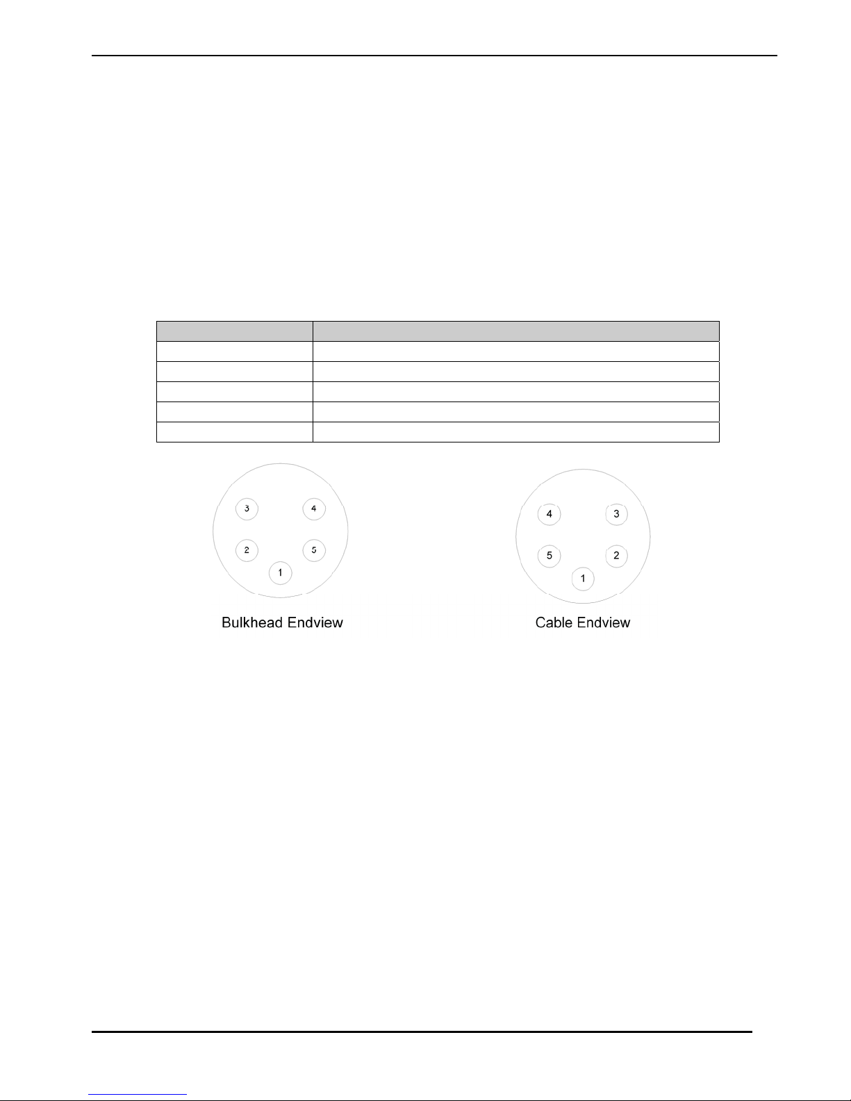
Appendix C: Connector Pinouts for LISST-100X
The LISST-100X has 3 separate underwater connectors. A 5-pin, a 6-pin,
and a 3-pin connector. The photograph above shows the placement of each
connector. The text below describes detailed wiring for each connector.
Communications and Power Connector (5 pin connector)
Connector Manufacturer: Impulse Enterprise, Inc. San Diego, CA, USA
Connector Part Number (Bulkhead): MCBH-5-MP Stainless Steel
Mating Cable Part Number: MCIL-5-FS
Connector Pin # Use
1 Power/Serial Ground
2 External Power In (+9V nom. 6-12V)
3 Power/Serial Ground
4 Serial Out (to DB-9 Pin 2)
5 Serial In (to DB-9 Pin 3)
LISST – 100 User’s Guide 66
Page 71
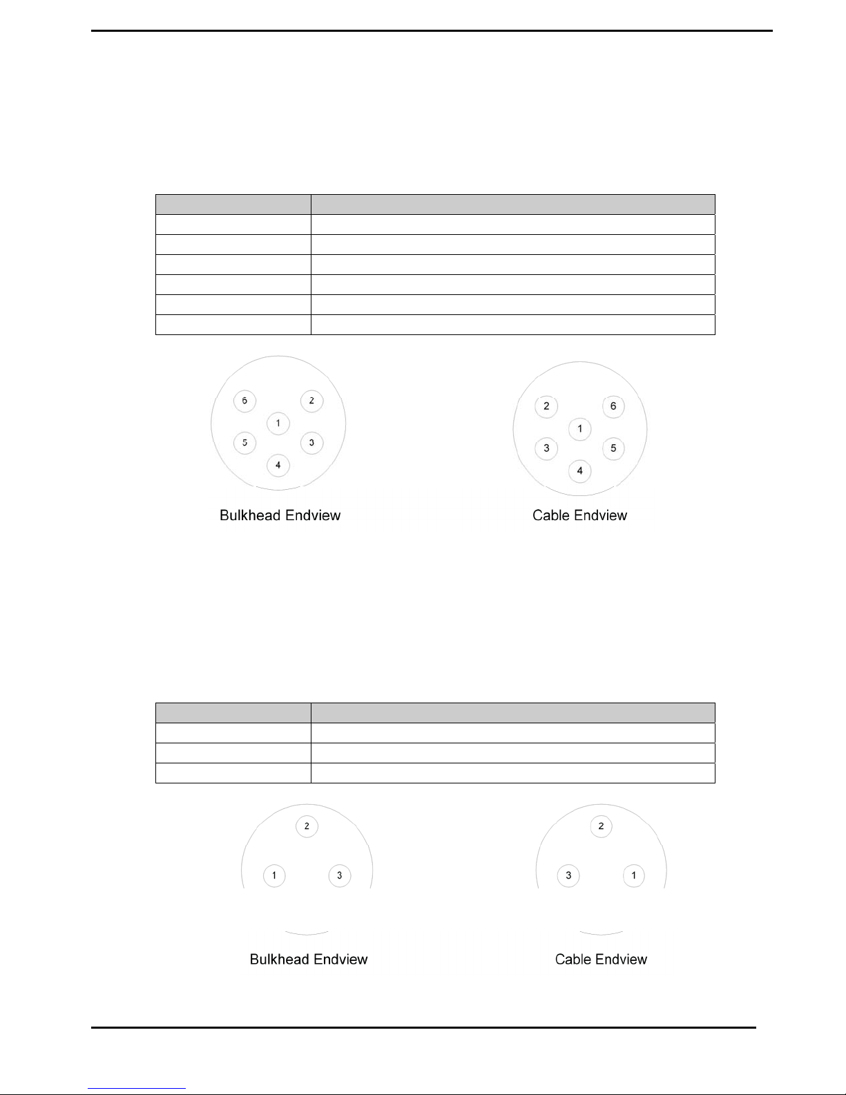
Auxiliary Input Connector (6 pin connector)
Connector Manufacturer: Impulse Enterprise, Inc. San Diego, CA, USA
Connector Part Number (Bulkhead): MCBH-6-MP Stainless Steel
Mating Cable Part Number: MCIL-6-FS
Connector Pin # Use
1 Digital Ground
2 Digital In #1
3 Digital In #2
4 No Connection
5 Analog In (0 to 2.50V max)
6 Analog Ground
BioBlock Connector (3 pin connector)
Connector Manufacturer: Impulse Enterprise, Inc. San Diego, CA, USA
Connector Part Number (Bulkhead): MCBH-3-MP Stainless Steel
Mating Cable Part Number: MCIL-3-FS
Connector Pin # Use
1 Signal Ground
2 Signal (Open/Closed)
3 Battery Sense
67 LISST – 100X User’s Guide
Page 72
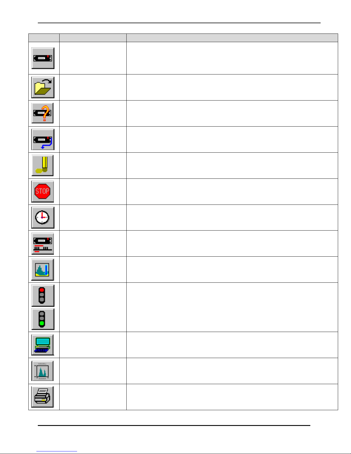
Appendix D: LISST-SOP Software Button Description
Button Label Description
Runs the instrument for Real-Time operation.
Open Real-Time
Session
Note: instrument must be already configured for real-time sampling and
be running (i.e. not hibernating). [To wake from hibernation, choose Wake Up
LISST from LISST menu
.]
Open
Query Instrument
Offload
Erase
Stop
Set Instrument
Clock
Operating Modes
Open raw or processed file. Depending on extension of file requested to
open, the appropriate procedure is started.
Queries instrument for it’s current configuration and displays the
information to the screen.
Offloads stored data to a file for later processing.
Erases the datafile by resetting the datafile pointer, (variable D in former
versions), to zero.
Sends a CTRL-C to the instrument to stop a running program. Also sends
PCLR 10 to turn off main power.
Sets the internal instrument clock to match the currently connected
computer clock
Opens the Instrument Sampling Configuration window where operating
mode and sampling schemes can be configured.
Collect Background
Opens the real-time background collection windows where backgroundscattering files can be collected in real-time.
When the instrument communication has not been initialized the
Connect/Disconnect button will be a red light. Pressing the button will
Connect/Disconnect
toggle the communications status. When the Connect/Disconnect button
is showing a green light the instrument communication has been
Open Terminal
initialized. Pressing the button will disconnect the instrument.
Pressing the Open Terminal button will bring up the terminal window for
communication with the instrument including Start and Stop buttons.
The Program Settings button bring up the general settings windows for
Program Settings
Print
LISST – 100 User’s Guide 68
setting display parameters and other software settings, such as File
Output, Com Port settings, and Plot .
When viewing processed data the Print button will be activated. Pressing
the button will send the current display to the printer.
Page 73

Appendix E: Software Upgrade Installation Procedure
The following procedure describes the installation of the LISST-SOP Version 4.60 software for users
who have previously received an instrument with Version 3.xx software. Instruments shipped after
August 19, 2002 were shipped with a version of the SOP software and do not require the following
procedures.
Step 1) Download Install file: The LISST-SOP Version 4.60 is available from the Sequoia
Scientific web site. The file downloads are restricted to existing customers only. Existing customers
can register for download by filling out the form on the website. When propmted for a instrument
serial number enter a valid 4 digit serial number. The files can then be downloaded. Future visits to
the download page can be accessed by entering the email and password selected at the time of
registration. Choose the file labeled “LISST-SOP Version 4.60 software for the LISST-100X”. Save
this file to disk.
The LISST-SOP_Install.EXE file is a self-extracting Zip file that contains the files required to install
the LISST-SOP software. This will include SETUP460.EXE, LISST1004.TTB, InstrumentData.txt,
and some instrument specific files for the example instruments #1004 and #1005. Run the program
and press OK to extract the files into a temporary folder of your choice. Before running the
SETUP460.EXE program there are a few tasks that must be performed.
Step 2) Configure Instrument Specific Files: The downloaded install file contains some generic
instrument specific files. These files will need to be replaced with files from the folder containing the
previous version of the LISST software. Copy the RingArea_1xxx.ASC file and the
Factory_ZSC_1xxx.ASC files from the previous version’s folder or the floppy disk sent with the
instrument to the LISST-SOP install folder. The xxx should be replaced with the serial number of the
instrument. For example, for unit 1001 the files should have the following names,
RingArea_1001.ASC file and Factory_ZSC_1001.ASC. Some older versions of the software did not
use this naming convention. If there are no files with serial numbers in the name copy the
RingArea_B.ASC (or RingArea_C.ASC for type C instruments) to the new folder and rename it using
the serial number naming convention as shown above. Similarly, copy and rename the
Factory_ZSC.ASC file. If multiple instruments are to be used with the LISST-SOP copy a RingArea
and Factory_ZSC file for each instrument to the new folder. The example files for instruments 1004
and 1005 can be deleted if desired.
Step 3) Edit InstrumentData.txt: The InstrumentData.Txt file contains a listing of a few basic
properties of each instrument to be used with the LISST-SOP software. Open the file using any text
editor such as Notepad. The file contains five comma-delimited columns of numbers. The first
column is the four-digit serial number of the instrument. The serial number cannot contain any
letters, only numbers. The second column is the instrument type (A, B, or C). Type A is the early 5500 micron unit. Type B is the 1.25-250 micron unit. Type C is the 2.5-500 micron unit. The third
column is the memory size. The options are either 529000 (standard) or 2102000 (2Mb upgrade) for
the orginal LISST-100. For the LISST-100X instrument enter 2102000. The fourth column is the
Calibration Constant. This value is instrument specific and can be found in the LISST.INI file in the
C:/Windows directory from the previous installation. It can also be found by selecting “Edit
Calibration Constants” in the previous versions. The fifth column is an indicator for the LISST-100X
type instruments. Place an X in this column for the LISST-100X instruments and leave it blank for
the LISST-100 instruments. Save the changes to the InstrumentData.Txt file.
69 LISST – 100X User’s Guide
Page 74

Step 4) Edit LISST.INI: The LISST-SOP software is designed to support the use of multiple
instruments. The LISST.INI file contains the calibration values for the auxiliary parameters for each
instrument to be used. Before installing the LISST-SOP rename the LISST.INI file in the Windows
folder to LISSTV3.INI and copy it to the temporary install directory. Open the LISSTV3.INI file with
Notepad. Also open the LISST.INI file in the temporary install directory. In the new LISST.INI file
there will be two instrument specific sections labeled [LISST1004] and [LISST1005] these sections
will need to be replaced with the correct calibration values for each instrument. Each instrument will
have its own section with a heading that is [LISSTxxxx] where xxxx is replace with the serial number
of the instrument. The previous version LISSTV3.INI will have a section labeled [Instrument1]. This
section can be copied from the old LISST.INI file for each instrument and placed into the new
LISST.INI file. Save the changes to the new LISST.INI file. During the setup of the software this file
will be copied to the Windows folder. The existing LISST.INI file will be renamed LISST.old.
Step 5) Run Setup460.EXE and configure software: Run the Setup460.exe program from the
floppy drive. From the Start menu select Run and enter A:/Setup460.exe. A Welcome screen will
appear. Choose Next to continue to the Destination Directory screen. The default directory is
C:\program files\Sequoia\LISST100. Use the Browse button to choose a different directory. Once a
directory is chosen press Next. Press Next again to start the install process. When it is completed
press OK to finish and exit the setup program. From the Start menu navigate to Programs then
Sequoia Scientific then LISST. If a desktop icon is desired, right click on LISST and choose “Send
To” and then “Desktop as icon”. This will create an icon on the desktop for later use. Note: the “Start
In” directory must be the same as the LISST.EXE program. Start the program by double clicking on
the icon or choosing LISST from the Start menu. From the File menu choose Settings. Select the
File Locations tab. The directory shown should be the same as the installation directory. If it is not,
use the Browse button to navigate to the correct directory. The default directory is C:\program
files\Sequoia\LISST100.
Step 4) Configure and Install Base program (for Orginal LISST-100 instruments only): The
LISST-100X no longer uses a Base Program. The following description is for older style LISST-100
instrument that do require a Base Program.
The Base program is a combination of all of the previous TTB programs. The LISST-SOP program
is used to choose the desired settings that are then used to command the Base program. Before
loading this program on to each LISST instrument we must first configure it with the correct serial
number and memory size. Open the LISST1004.TTB program with any text editor such as Notepad.
Change the serial number to match the instrument serial number at Line 1815. If the instrument is
configured with a 2Mb memory upgrade you will also need to change Lines 10010 and 13620. At
these lines there are two lines of code. One line has REM in front of it. To switch lines move the
REM from one to the other. Save the file as LISSTxxxx.TTB where xxxx is the serial number of the
instrument. This step should be repeated for each instrument. Note: Some instruments may have
custom features such as the options Conductivity and Temperature sensor. These instruments will
require a custom Base program that has been modified to work with the instrument. Contact Sequoia
Scientific for more details.
After changing the serial number, this program can then be loaded into the instrument. Before
installing the program into the instrument using the new LISST software, connect the
communications cable and establish a connection using the new Terminal window of the LISST
software. To open the terminal window choose Terminal Window from the Communications menu.
Make sure that no programs are running, the OK> prompt is displayed, and any resident program is
cleared by issuing a NEW command.
To install the new base program from the LISST-SOP program select the Send Program option from
the LISST menu. A file selection dialog box should be displayed. Choose the program that is to be
LISST – 100 User’s Guide 70
Page 75

loaded on to the instrument and select OK. A transfer status display will appear as the program is
loaded. To confirm the loading issue a LIST command from the Terminal Window.
The software and instrument are now ready to use.
71 LISST – 100X User’s Guide
Page 76
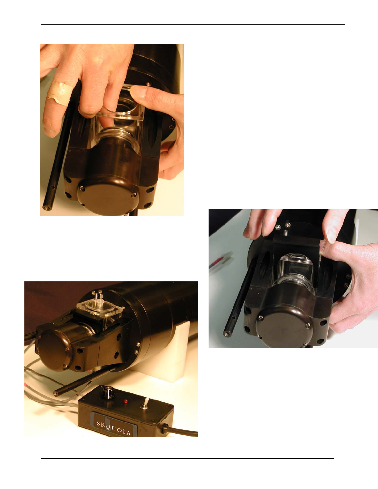
Appendix F: Horizontal Chamber Installation Procedure
Step 1) Before installing the Small Volume Horizontal
Chamber first clean the windows of the LISST-100. It
will also be necessary to remove the endcap ring and
standoffs on the optics endcap. Remove the three screws
on the ring and then unscrew the standoffs. Remove the
Spacer and push the Slider into toward the center of the
chamber. The Mixing bar can be left in the chamber or
removed.
Step 2) Carefully insert the Chamber into the optical
path of the LISST-100. Be careful not to touch the orings to either glass windows. The Slider should mate to
the cone shape of the transmit optics. By reaching in
from the top of the chamber push the Slider out until the
chamber is up against the optics endcap. The o-ring in
the slider should just be starting to engage with the wall
of the chamber. It may be necessary to press on the top,
bottom and sides of the Slider to get it to slide out with
out binding.
Step
3) Once the slider is positioned such that the o-ring is
engaging in the wall of the chamber the Spacer can be
inserted between the outside wall of the chamber and the
lip of the Slider. The tapered side of the spacer should go
against the Slider lip. This will cause compression of the
o-rings and seal the chamber.
LISST – 100 User’s Guide 72
Step 4) The chamber can now be filled with clean
water. It is highly recommended to do a
background scatterfile after assembly to make sure
that the windows are still clean. It is NOT
necessary to have water around the chamber as
with previous designs.
Page 77
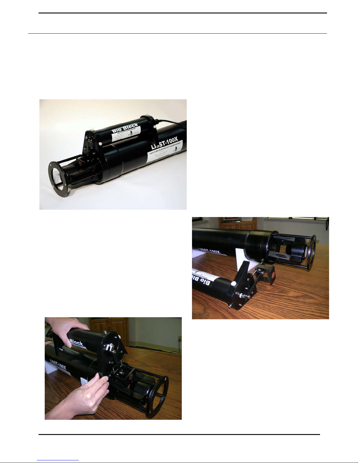
Appendix G: BioBlock Installation and Use
The BioBlock Anti-Biofouling Shutter system is a bolt-on option that is available for the LISST-25X, LISST100, and LISST-100X. Copper disks are placed very near the optical widows. The copper discourages any
biology from growing on the optical windows. The BioBlock is self-contained with its own battery pack. It
uses a 5V logic signal from the dedicated BioBlock connector on the LISST-100X connector endcap. This
appendix is separated into three parts. The first section covers the installation of the BioBlock onto the LISST100X. The second section discusses configuring the firmware in the instrument to recognize the BioBlock and
use it during data collection. The third section
discusses general maintenance such as cleaning and
battery replacement.
Please note that the installation and maintenance of
the BioBlock on the older LISST-100 instruments
is very similar to the procedures described here for
the LISST-100X. However, the BioBlock
configuration in the firmware is very different. If
you are using an older version LISST-100 please
contact your authorized Sequoia representative for a
more correct procedure for using the BioBlock with
the LISST-100.
The figure on the left shows the fully assembled
BioBlock on the LISST-100X.
Installation Instructions for the LISST-100X
Step 1) The BioBlock for the LISST-100X is shipped
fully assembled and ready to mount onto the LISST100X. Please note that the main body of the BioBlock
can be used on the LISST-25X and LISST-100 in
addition to the LISST-100X. Therefore it is important to
specify which type of instrument the BioBlock will be
used with at the time the order is placed. The photo on
the right shows the assembled BioBlock next to the
LISST-100X. The BioBlock is shown in the Closed
(windows covered) position. This position is best for
correctly positioning the unit during installation. The
73 LISST – 100X User’s Guide
BioBlock should be removed from the LISST-100X
in the Closed position to facilitate re-installing it at a
later date. The BioBlock may be commanded to go to
the Closed position prior to installation by connecting
it to the LISST-100X and using the LISST-100X
software. Do not manually rotate the crank arm that
drives the shutter.
The BioBlock has two main parts. The main
cylindrical body contains the motor, batteries, and
electronics. Mounted to the end of the main body is
the translating shutter assembly with copper plates.
The shutter assembly is attached to the rotating crank
arm with a plastic arm.
Page 78
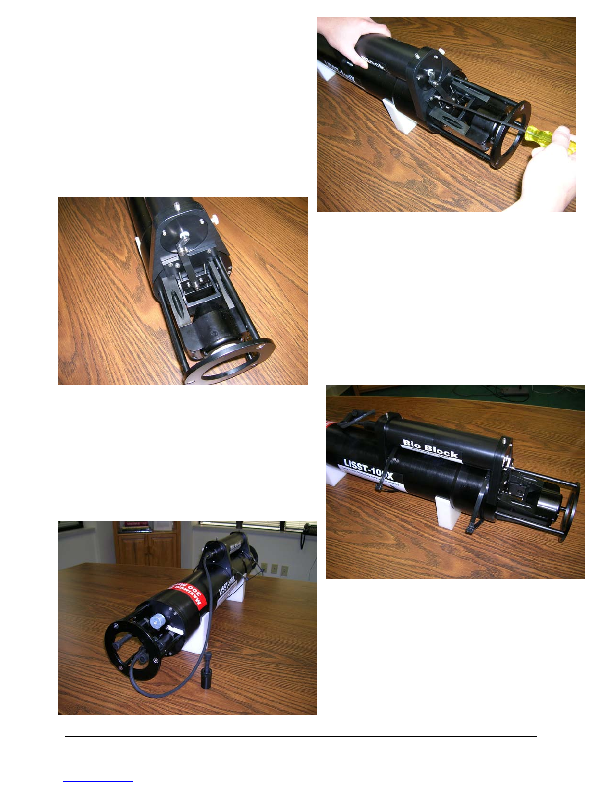
Step 2) The figure above shows how the BioBlock is
inserted between the triangular Crossbar Standoffs of
the LISST-100X. Before installing the BioBlock we
must first remove one of the screws on the endcap.
Rotate the LISST-100X to match the photo. The two
endcap screws should be above the Crossbar Standoff
on the left. One is threaded into the endcap and the
other is longer and threaded into the instrument
housing. Remove the shorter screw such that the
threaded screw hole is empty. This is the most
clockwise screw of the pair. This threaded hole will be
used to hold the BioBlock in place.
Step 3) Slowly slide the BioBlock shutter assembly
straight down between the Crossbar Standoffs and the
windows (the LISST-100X sample volume), taking
care not to drag the copper plates across the windows.
The assembly is designed to fit snugly between the
Crossbar Standoffs. If the fit is too tight the plastic
sides of the assembly may be lightly sanded until the
parts fit together easily. Holding the BioBlock body
firmly against the LISST-100X, and ensuring that the
shutter assembly is centered in the LISST-100X
sample volume, install and tighten the mounting
screw. This screw is provided with the unit and is not
the screw that was removed in Step 2.
Step 4) Use large tie-wraps to secure the BioBlock body
to the LISST-100X, as shown in the photo on the right.
The tie-wraps should be placed over the bolts extending
from the mounting brackets. Trim excess ends of tiewraps.
Step 5) Connect the BioBlock cable to the LISST100X. Verify normal operation by cycling the
system using the LISST.EXE software. The
BioBlock shutter should position itself smoothly
during cycling, with no binding. If necessary,
loosen the mounting screw slightly and adjust the
position of the BioBlock slightly to improve
operation, and then re-tighten the screw.
LISST – 100 User’s Guide 74
Page 79

Configuring and Operating the BioBlock on the LISST-100X
The LISST-100X comes pre-configured for use with the BioBlock. There is a dedicated BioBlock connector
on the endcap and the firmware is designed to utilize the BioBlock shutter during sampling. The only thing
remaining is to inform the firmware that the BioBlock has been installed. To do this a simple two letter
command has been added to tell the instrument the BioBlock is attached. The command is BB (short for
BioBlock). The summary of the command is below.
BB BioBlock Configuration and Test Command
Syntax: BB or bb
Description: Configure the BioBlock Connection Setting and send test commands.
Example: input: BB 1
output: BioBlock is now connected!
Input options:
0 = BioBlock is not connected.
1 = BioBlock is connected.
10 = BioBlock is connected and issues a command to close the BioBlock.
11 = BioBlock is connected and issues a command to open the BioBlock.
As shown in the shown in the table above the BB command has multiple input options. In addition to telling
the firmware that the BioBlock is connected, the command can also be used for testing the operation of the
BioBlock. For example, issuing a BB 10 command will enable the connection and send the command to close
the BioBlock. A BB 11 command will also enable the connection and send an open command.
During normal sampling the BioBlock will be commanded to open before each sample is collected. After the
sample is recorded the time until the next sample is computed. If the time remaining is less than 30 seconds
the BioBlock will remain open. If the time is greater than 30 seconds the BioBlock will close and then reopen
two seconds before the next sample.
When using the Real Time mode of the LISST-SOP software, the BioBlock will not be commanded to open at
the beginning of sampling. Therefore it must be manually opened using the BB 11 command.
To issue the BB command, open the Terminal window on the standard LISST-SOP Windows software. At the
L100X>> prompt type BB followed by the input option. Pressing Enter will set the BioBlock connection and
issue any open or close commands. If a Display Status (DS) command is now issued the listing of the
instrument status will now include a message that the BioBlock is now connected.
The BioBlock uses two standard alkaline D batteries for power. The electronics inside the BioBlock includes a
battery monitor. If the voltage of the battery is too low a signal will be sent to the LISST-100X. If LISST100X sees that the BioBlock battery is low it will command the BioBlock to remain open. By monitoring the
battery, the BioBlock can be left in the open position before the battery voltage is too low.
75 LISST – 100X User’s Guide
Page 80

BioBlock Battery replacement
The BioBlock uses two standard Alkaline D cells to power its operation. The following procedure can be used
to replace the batteries. It is recommended that the batteries be replaced before each extended deployment.
Step 1) Disconnect the cable attaching the BioBlock to the LISST-100X at the BioBlock. The BioBlock and
remain connected to the LISST-100X if desired.
Step 2) Remove the three screws holding the connector endcap to the main body of the BioBlock. These
screws are 4-40UNC socket head cap screws that are 5/8 inches long. Carefully remove the endcap from the
main body by gently pulling on the endcap with a slight twisting motion. Be careful not to pull the assembly
out too far. Wires connect this endcap to the internal circuitry and therefore the travel is limited. The two
batteries are held in place by a battery mount attached to the connector endcap. Remove the batteries and
replace with fresh alkaline batteries. If desired wrap each battery with electrical tape to keep it in place during
installation. Please note that the battery mount is flexible and when inserted in to the housing the squeeze on
the batteries will increase to insure a good connection. Make sure that the tape does not impede the batteries
from sliding and making good contact.
Step 3) Check the o-ring on the connector endcap. The surface should be clean and free of cuts. If needed,
add a very light coating of o-ring grease to make assembly easier. The o-ring is a Parker O-ring #2-133.
Carefully slide the battery assembly into the housing. It should be possible to rotate the assembly after
installation to line up the screw holes. Install the three screws holding the endcap in place. Tighten the
screws to just slightly tighter than finger tight. The sealing of the endcap is not dependent on the tightness of
the screws. Since the metal screws are threaded into plastic it is easy to over tighten the screws and strip the
threads in the housing. Do not over tighten the screws.
Step 4) Reattach the cable to the LISST-100X and test the operation using the BB 11 and BB 10 commands.
The commands can be issues through the Terminal window of the LISST-SOP software.
LISST – 100 User’s Guide 76
Page 81

Warranty
STATEMENT OF LIMITED, EXTENDED WARRANTY
This Statement of Limited, Extended Warranty applies to the products ("Products") being purchased by
("Customer") from Sequoia Scientific, Inc. ("SEQUOIA") pursuant to PO
LISST-100X Particle Size Analyzer Serial Number #
SEQUOIA and Customer agree as follows:
1. Limited Warranty
SEQUOIA warrants that upon delivery by SEQUOIA (a) the Products will be free from defects in materials and workmanship, (b) the
Products will perform substantially in accordance with SEQUOIA's applicable specifications, and (c) any Products (or components or
parts thereof) that are manufactured by SEQUOIA do not infringe any U.S. patent or copyright.
2. Correction of Non-Compliance
If any Product does not comply with the warranties set forth in 1(a) and 1(b) above, SEQUOIA will, at its option, either (a) repair the
Product, (b) replace the Product, or (c) refund the purchase price paid by Customer to SEQUOIA for the Product; provided that
Customer gives SEQUOIA written notice of the noncompliance within one (1) year after SEQUOIA's delivery of the Product (as the
same may be extended for repaired or replacement Products as provided for herein, the "Warranty Period"). If Customer does not give
SEQUOIA such written notice within the Warranty Period, then such warranties will be satisfied in full. Customer will cooperate with
SEQUOIA's efforts to repair or replace any noncomplying Product. Without limiting the generality of the foregoing, Customer will
comply with SEQUOIA's request for return of any such Product to SEQUOIA (in which event SEQUOIA will pay for round-trip
shipment within the United States) or for access to accomplish the repair or replacement on Customer's premises. As to any Product
repaired or replaced by SEQUOIA, the Warranty Period will end upon the later of one (1) year after SEQUOIA's delivery of the
original Product or 90 days after SEQUOIA's delivery of the repaired or replacement Product. Any Product, component, part or other
item replaced by SEQUOIA becomes the property of SEQUOIA.
(the "Order"). The Products include, but are not necessarily limited to, the following:
3. Infringement Indemnification
If any Product does not comply with the warranty set forth in 1(c) above, SEQUOIA will defend and indemnify Customer against any
third-party claim asserted in any proceeding against Customer based on this noncompliance; provided that Customer gives SEQUOIA
prompt written notice of the claim, SEQUOIA has exclusive control over the defense and settlement of the claim, Customer provides
such assistance as SEQUOIA may request in connection with the defense and settlement of the claim (in which event SEQUOIA will
reimburse the reasonable out-of-pocket costs incurred by Customer to provide such assistance), Customer does not settle the claim
without the prior written consent of SEQUOIA and, upon SEQUOIA's request, Customer returns the Non-Complying Product to
SEQUOIA for modification, replacement or a refund of the purchase price paid by Customer to SEQUOIA for the Non-Complying
Product, less a reasonable allowance for Customer's use prior to return.
4. Exclusive Warranties
THE WARRANTIES SET FORTH IN PARAGRAPH 1 ABOVE ARE EXCLUSIVE AND IN LIEU OF ALL OTHER
WARRANTIES, EXPRESS OR IMPLIED. SEQUOIA DISCLAIMS ANY AND ALL WARRANTIES, EXPRESS OR IMPLIED
(INCLUDING, BUT NOT LIMITED TO, ANY IMPLIED WARRANTY OF MERCHANTABILITY OR FITNESS FOR A
PARTICULAR PURPOSE, AND ANY IMPLIED WARRANTY ARISING FROM COURSE OF PERFORMANCE, COURSE OF
DEALING, OR USAGE OF TRADE) OTHER THAN THOSE SPECIFICALLY SET FORTH IN PARAGRAPH 1.
5. Exclusive Remedies
CUSTOMER'S RIGHTS AND REMEDIES SET FORTH IN PARAGRAPHS 2 AND 3 ABOVE ARE EXCLUSIVE AND IN LIEU
OF ANY AND ALL OTHER RIGHTS AND REMEDIES FOR ANY BREACH OF OR OTHER FAILURE TO COMPLY WITH
ANY WARRANTY WITH REGARD TO ANY PRODUCT.
6. No Consequential Damages
SEQUOIA will not be liable for any indirect, incidental, special or consequential damages, any cover, or any loss of revenue, profit,
data or use.
7. Limitations of Liability
77 LISST – 100X User’s Guide
Page 82

SEQUOIA's liability (whether in contract, tort, or otherwise; and notwithstanding any fault, negligence, strict liability or product
liability) with regard to any Product (including, but not limited to, any breach of or default under the Order by SEQUOIA) will in no
event exceed the purchase price paid by Customer to SEQUOIA for such Product. Further, SEQUOIA will not be liable for, or be in
breach of or default under the Order on account of, any delay or failure to perform as a result of any cause, condition or circumstance
beyond SEQUOIA's reasonable control.
8. Statute of Limitations
Customer will not commence any action based on breach of warranty with respect to any Product more than 18 months after
SEQUOIA's delivery of such Product.
9. Software
The Products may include or be delivered with certain computer programs, databases or other software that is proprietary to
SEQUOIA. SEQUOIA hereby grants Customer a nonexclusive license to use such software solely for the purpose of operating
Products. Customer will not: use any such software for any other purpose; modify, adapt, translate, or create derivative works based
on any such software; or disassemble, decompile or reverse engineer any such software. No title to or ownership of any software or
intellectual property rights are transferred to Customer.
10. U.S. Government Restricted Rights Notice
All software, data, technical information, and written materials provided by SEQUOIA are provided with restricted rights. Use,
duplication, or disclosure by the government is subject to restrictions as set forth in subparagraph (c)(1)(ii) of the Rights in Technical
Data and Computer Software clause at 48 C.F.R. § 252.227-7013 or in subparagraph (c)(2) of the Commercial Computer SoftwareRestricted Rights clause at 48 C.F.R. § 52.227-19, as applicable. Portions of these items may be unpublished. SEQUOIA reserves all
rights under applicable copyright laws.
11. Controlling Document
In the event of any conflict or inconsistency between any provision of this Statement of Limited Warranty and any other provision of
the Order, the provision of this Statement of Limited Warranty will control.
12. Controlling Law
This Statement of Limited Warranty will be governed by the laws of the State of Washington without reference to its rules relating to
choice of law, except to the extent preempted by the laws of the United States. The U.N. Convention on Contracts for the International
Sale of Goods will not apply.
CUSTOMER:
By:_____________________________________
Title:____________________________________
Sequoia Scientific, Inc.
By:_____________________________________
Title:____________________________________
SEQUOIA:
LISST – 100 User’s Guide 78
 Loading...