

Page 1
Multi-filter Mono/Paraphonic Synthesizer
PRO 3
Page 2

Page 3

User’s Guide
PRO 3
Version 1.0
January, 2020
Sequential LLC
1527 Stockton Street, 3rd Floor
San Francisco, CA 94133
USA
©2020 Sequential LLC
www.sequential.com
Page 4

Tested to Comply
With FCC Standards
FOR HOME OR OFFICE USE
This device complies with Part 15 of the FCC Rules. Operation is subject to
the following two conditions: (1) This device may not cause harmful interference and (2) this device must accept any interference received, including
interference that may cause undesired operation.
This Class B digital apparatus meets all requirements of the Canadian
Interference-Causing Equipment Regulations.
Cet appareil numerique de la classe B respecte toutes les exigences du
Reglement sur le materiel brouilleur du Canada.
For pluggable equipment, the socket-outlet shall be installed near the equipment
and shall be easily accessible.
For Technical Support, email: support@sequential.com
Page 5

Table of Contents
A Few Words of Thanks ...............................xi
Chapter 1: Getting Started ..............................1
Rear Panel Connections ................................. 2
Using USB ..................................................4
Setting Up the Pro 3 ..................................... 5
Using the Main Display .................................. 6
Sound Banks ........................................... 7
Selecting Programs ...........................................7
Editing Programs ....................................... 8
Comparing an Edited Program to its Original State ...................8
Creating a Program from Scratch. . . . . . . . . . . . . . . . . . . . . . . . . . . . . . . . . 9
Saving a Program ...................................... 10
Canceling Save .............................................11
Comparing Before You Save ...................................11
Using Paraphonic Mode ................................. 12
Exploring the Pro 3 in Greater Depth ...................... 13
Chapter 2: Pro 3 Controls ..............................14
Oscillators ............................................ 15
Exploring Oscillator 3 ........................................17
Oscillator Parameters (Front Panel) ..............................18
Additional Oscillator Parameters (Display Menus) ...................19
TAB 1 - Osc Tuning ..........................................19
TAB 2 Osc Shape ............................................20
TAB 3 - Osc Level ...........................................20
TAB 4 - Osc Misc ............................................21
Page 6

Mixer ................................................ 21
Mixer Parameters (Front Panel) ................................22
Additional Mixer Parameters (Display Menu) .......................23
TAB 2 - Ext in ...............................................23
TAB 3 - Ext in Env ...........................................23
Filters ................................................ 24
Filter Parameters (Front Panel) .................................27
Additional Filter Parameters (Display Menus) ......................28
TAB 3 - ADSR ...............................................29
TAB 4 - Env Amt .............................................30
Envelope Parameters (Front Panel) .............................33
Additional Filter Envelope Parameters (Display Menus) ..............34
TAB4 - Env Amount ..........................................34
Amplier Envelope ..................................... 35
Amplier Envelope Parameters (Front Panel) ......................37
Additional Amplier Parameters (Display Menus) ...................38
TAB 1 - VCA ................................................38
TAB 4 - VCA Env Amount ......................................38
Auxiliary Envelopes .................................... 39
Auxiliary Envelope Parameters (Front Panel) ......................40
Additional Auxiliary Envelope Parameters (Display Menus). . . . . . . . . . . . 41
TAB 1 - Aux 1 Destination .....................................41
TAB 3 - Aux 1 Env Amount .....................................41
Low Frequency Oscillators .............................. 42
LFO Parameters (Front Panel) .................................43
Additional LFO Parameters (Display Menus) .......................44
TAB 1 - LFO Shape ..........................................44
TAB 2 - LFO Control ..........................................45
TAB 3 - LFO Dest ............................................46
Modulation ........................................... 46
Modulation Parameters (Front Panel) ............................48
Additional Mod Matrix Parameters (Display Menu) ..................48
Modulation Examples .........................................48
Effects ............................................... 50
Effects Parameters (Front Panel) ................................52
Page 7

Arpeggiator ........................................... 54
Arpeggiator “Momentary Sustain” Mode ..........................56
MIDI Note Output from the Arpeggiator ...........................57
Arpeggiator Parameters (Display Menus) .........................58
Clock Parameters ......................................59
Sequencer ............................................ 60
Normal, Gated, and Trigger Modes ..............................60
Programming the Sequencer ...................................62
Recording Phrases/Sequences A,B,C, or D. .......................63
Sequencing Parameter Changes in Real-Time .....................64
Copying a Sequence from One Track to Another ....................65
Copying and Pasting an Entire Sequence .........................65
Muting a Sequence Track. . . . . . . . . . . . . . . . . . . . . . . . . . . . . . . . . . . . . . 66
Creating An Extended Sequence ...............................66
Paraphonic Sequencing ......................................67
Adding Rests, Ties, and Velocity ................................68
Editing Duration .............................................72
Adding Ratcheting ...........................................72
Editing Other Elements of a Sequence ...........................73
Setting or Changing the Destination of a Track .....................74
Recording Additional Sequencer Tracks for Modulation. . . . . . . . . . . . . . . 75
Using Slew .................................................76
Turning off the Sequencer’s “Notes” Track ........................76
Sequencer Parameters (Front Panel) ............................77
Additional Sequencer Parameters (Display Menus). . . . . . . . . . . . . . . . . . 78
Cue Program .......................................... 79
Tuned Feedback ....................................... 80
Feedback Parameters ........................................81
Master Volume/Program Volume .......................... 82
Transpose ............................................ 83
Hold ................................................. 83
Glide ................................................. 83
Glide Modes ................................................84
Page 8

Pitch and Mod Wheels .................................. 86
Pitch Wheel ................................................86
Modulation Wheel. . . . . . . . . . . . . . . . . . . . . . . . . . . . . . . . . . . . . . . . . . . . 87
Touch slider .......................................... 88
Adding Aftertouch ..................................... 89
Distortion ............................................. 90
Play List .............................................. 91
Miscellaneous Parameters .............................. 93
Key Modes Tab ..............................................93
Gate Source ................................................94
Scale .....................................................94
Glide Tab ..................................................95
Pitch Wheel Tab .............................................95
Global Settings ........................................ 96
Chapter 3: Programming the Pro 3 ...........................104
Synthesis 101: Synth Bass ............................. 104
Creating Synth Brass .................................. 107
Turning Synth Brass into a Paraphonic String Pad .................108
Creating a Hard-Sync Lead ............................. 110
A Final Word ............................................... 111
Chapter 4: Using the Pro 3 with External Devices .........112
Processing External Audio ....................................112
Filtering External Audio Using the Envelope Follower ...............113
Syncing the Sequencer with an External MIDI Device ...............11 5
Using Pro 3’s CV Outs to Control a Modular Synth .................11 6
More About Pro 3’s CV Outputs ................................11 7
viii
Sequential
Page 9

Appendix A: Modulation Sources ......................119
Appendix B: Modulation Destinations ...................120
Appendix C: Troubleshooting and Support ..............122
Troubleshooting ............................................122
Resetting the Global Parameters ...............................124
Contacting Technical Support ..................................124
Warranty Repair ............................................125
Appendix D: Calibrating the Pro 3 ......................126
Calibrating the VCOs and Filters ...............................126
Calibrating the Pitch and Mod Wheels ...........................126
Resetting the Global Parameters ...............................126
Importing Programs and Banks ................................128
Appendix E: Alternative Tunings .......................130
Appendix F: MIDI Implementation ......................134
MIDI Messages ............................................136
NRPN Messages ...........................................140
Control NRPN Data .........................................147
SysEx Messages ...........................................147
Packed Data Format ........................................150
Pro 3 User’s Guide
ix
Page 10

THE SEQUENTIAL CREW
Art Arellano, Gerry Bassermann, Fabien Cesari, Bob Coover, Carson Day, Chris Hector,
Tony Karavidas, Mark Kono, Justin Labrecque, Andy Lambert, Michelle Marshall, Andrew
McGowan, Joanne McGowan, Julio Ortiz, Denise Smith, Tracy Wadley, and Mark Wilcox.
THE PRO 3 SOUND DESIGN TEAM
Rory Dow, Peter Dyer, GLASYS, Mike Hiegemann, Tim Koon, Tobias Menguser,
Drew Neumann, Bob Oxley, Francis Preve, Lorenz Rhode, Robert Rich, Matia Simovich,
Huston Singletary, James Terris, Mitch Thomas, and Taiho Yamada.
Special thanks to Kurt Kurasaki, Drew Neumann, and Robert Rich for wavetables!
x
Sequential
Page 11

A Few Words of Thanks
Thank you for purchasing the Pro 3, our latest effort to make the world’s greatest
monosynth. That’s a bold statement, but it’s true. Our biggest pleasure here at
Sequential is trying to outdo ourselves with each new instrument.
In many ways the Pro 3 is the evolution of a concept that started with the classic
Sequential Circuits Pro-One — pack as much power as possible into a compact
footprint and make it sound awesome. In this case, that power comes in threes:
three oscillators, three lters, three LFOs, plus our most powerful sequencer yet.
And there’s plenty of modulation; over thirty-two slots worth, in fact.
Our formula seems to have worked. The Pro 3 doesn’t just sound good, it sounds
amazing. We love this synth and hope you will, too.
So stop reading and starting playing!
Cheers,
Page 12

Page 13
Chapter 1: Getting Started
MODPITCH TOUCH
Headphones
Up
TRANSPOSE
Down
PITCH
MASTER VOLUME
DISTORTION
SHAPE
SHOW EFFECTS PARAM 1 PARAM 2
PARAM 3MIXEFFECT TYPE
EFFECT 1
EFFECT 2
ON/OFF
SHAPE MOD SYNC
BPM DIVIDE SWING
VELOCITY ATTACK DECAY SUSTAIN RELEASE AMOUNT
ATTACK DECAY SUSTAIN RELEASEAUX ENV AMOUNT
VELOCITY ATTACK DECAY SUSTAIN RELEASE AMOUNT
AMOUNT
GRUNGE
TUNING
PITCH SHAPE SHAPE MOD SYNC
AMOUNT
GLIDE RATE
GLIDE
HOLD PITCH SHAPE SHAPE MOD LOW FREQ
OSC 1 LEVEL
OSC 2 LEVEL
EXT AUDIO
NOISE
OSC 3 LEVEL
TAP TEMPO ARPEGGIATOR
SOURCE DESTINATION
VALUE
1 2
CUTOFF
DRIVE
BP
LP
NOTCH
LOW-PASS 1 LOW-PASS 2
Revert Write
CompareShow
GlobalMisc. Params
Play ListParaphonic
STATE-VARIABLE
4-Pole OTA 4-Pole Ladder 2-Pole OTA
HP
RESONANCE
STATE
FREQUENCY AMOUNT
1 2 3
1 2 3 4 5 6 7 8 9 10 11 12 13 14 15 16
TRACKS
SLEWSEQ LOCKCUE PGM
BANK
Inc
Dec
PROGRAM
TRACK SEL
notes/vel duration ratchet cutoff assign 1 assign 2 assign 3 assign 4 assign 5 assign 6 assign 7 assign 8 CV out 1 CV out 2 CV out 3 CV out 4
A B C D
SEQUENCE RECORD PLAY MODE RESETDIRECTION
fwd
Normal
Gated
Trigger
rev fwd/rev random
DESTINATIONSHAPE
LFO OSCILLATORS
MODULATION EFFECTS
MIXER
FILTER
ENVELOPES
AMP FILTER
TUNED
FEEDBACK
AUX
PRO 3
Writing to Bank:1 Program:1 A:
uper Bass
Hit ‘Write’ to Save Prog
Write Bank Write Prog Select Char Edit Char
S
Key AssignInsert Char Delete Char
OCTAVE
-1-2+1
+2
-1-2+1
+2
-1-2+1
+2
OCTAVE
OCTAVE
1
1
1
OSC 1OSC 2OSC 3
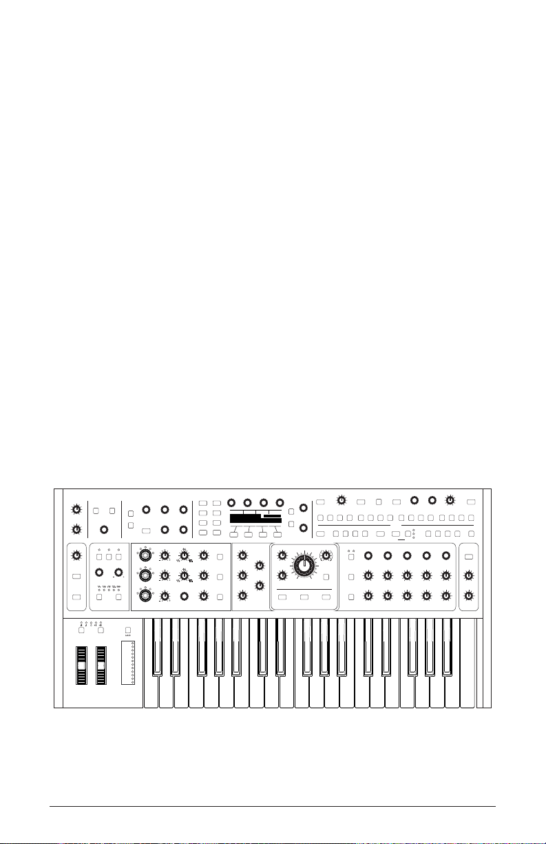
The Pro 3 is a hybrid synthesizer in the best sense of the word. It
combines the warmth and punch of two analog, voltage-controlled oscil-
lators and three types of classic analog lters with the versatility of a
third, digital wavetable oscillator and an array of digital effects.
This blend of technologies gives you an instrument that’s sonically satis-
fying to play, but also has power and exibility rivaling modular systems
through its extensive modulation capabilities and four control voltage ins
and outs.
This chapter of your user’s guide provides an overview of essential
tasks such as how to make basic audio connections and how to edit and
save sounds. Later chapters explain each of the parameters of the Pro 3,
as well as how to program sounds and how to use the global menu to
manage its overall behavior.
We’ve designed the Pro 3 to be as easy to use as possible. Its essential
controls are within easy reach on its front panel, so don’t hesitate to dive
in and start turning knobs and pressing buttons. Then, when you’re ready,
dig into this user’s guide to explore the deeper parts of the synth.
Pro 3 User’s Guide
Chapter 1: Getting Started
1
Page 14
5 6 7 8 9 10 11
21
43
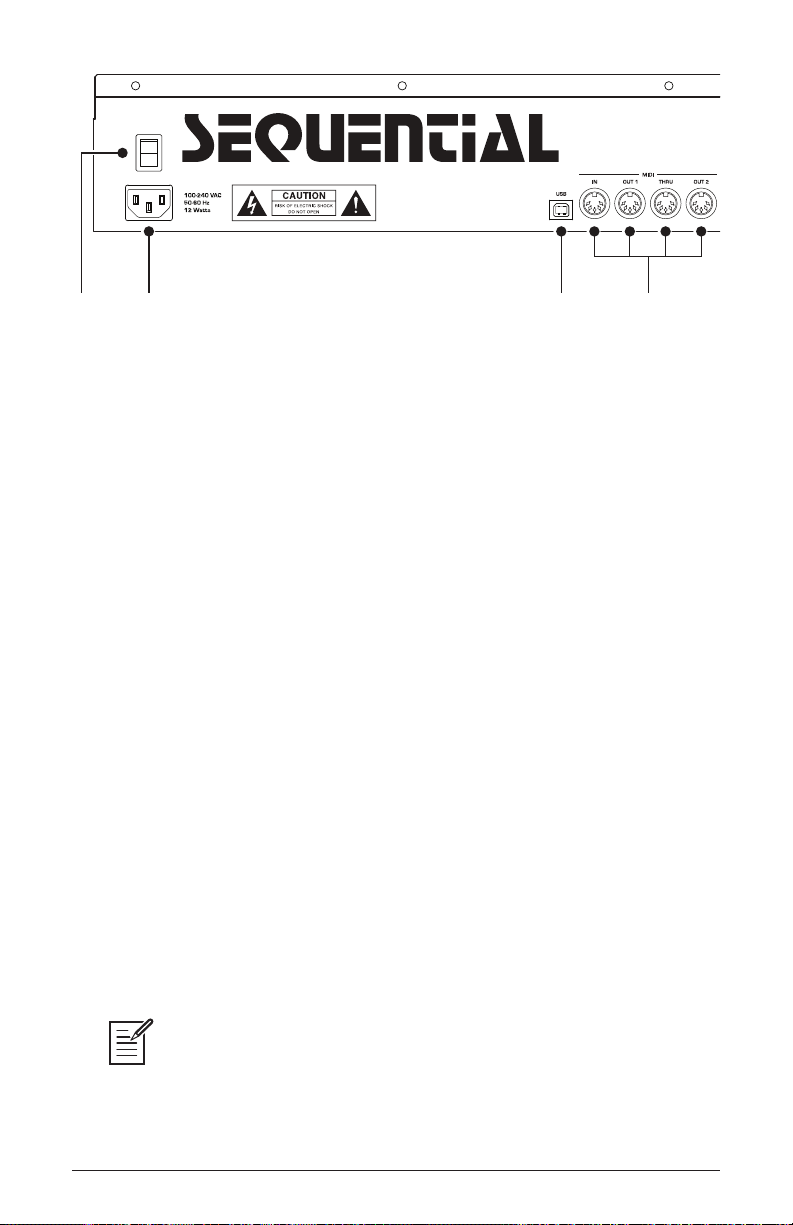
Rear Panel Connections
The rear panel of the Pro 3 has connectors for power, USB, MIDI, audio,
and pedals.
1. Power On/Off—This rocker switch controls power on and off to the
Pro 3.
2. AC Power Connector—Accepts a standard, grounded IEC power
cord. Operates over a range of 100 to 240 volts and 50 to 60 Hz.
3. USB—For bidirectional MIDI communication with a computer. The
Pro 3 is a Class Compliant USB device and does not require additional
drivers when used with Mac OS or Windows. See “Using USB” on page
4 for more information.
4. MIDI In, Out 1, Thru, Out 2—Standard 5-pin MIDI DIN connectors
for communicating with MIDI-equipped devices.
5. Footswitch—Accepts a momentary, normally open or normally closed
footswitch to control sustain or to latch the Arpeggiator on when keys
are held. Alternatively, an audio signal connected to the audio in jack can
be used to either control Sequencer/Arpeggiator playback, or to gate the
lter and amplier envelopes while notes are held.
Audio signals used to drive the Arpeggiator/Sequencer should not exceed 5
volts peak-to-peak.
Rear Panel Connections
2
Sequential
Page 15
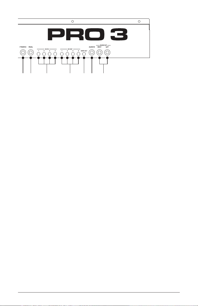
5 6 7 8 9 10 11
6. Pedal—Accepts a standard expression pedal that has a variable resis-
tor on a TRS (tip-ring-sleeve) ¼ inch phone plug. Once connected, you
can use the modulation matrix to route the pedal to control a variety of
things such as volume or lter cutoff frequency to add expressiveness to
live performance.
7. Control Voltage Ins 1-4—Standard 3.5 mm connectors. These jacks
accept a +/-5V signal for interfacing with modular synthesizers. They can
be congured for 1-volt-per-octave operation for gear that recognize that
standard.
8. Control Voltage Outs 1-4—Standard 3.5 mm connectors. These jacks
output a +/-5V signal for interfacing with modular synthesizers. They can
be congured for 1-volt-per-octave operation for gear that recognize that
standard.
9. Gate Out—Standard 3.5 mm connector. This jack outputs a 10-volt
on/off signal to switch a note on/off in external Sequencers and other
devices that support this type of connectivity.
10. Audio In—Unbalanced, ¼ inch audio input. The Pro 3 accepts exter-
nal audio signals for processing through this connector. Input level can
be adjusted using the ext audio knob in the Mixer section.
11. Audio Outputs—Unbalanced, ¼ inch audio outputs. The Pro 3
sounds great in stereo, but can be switched to mono if needed. See
“Global Settings” on page 96.
12. Headphones (on front) — ¼ inch stereo headphone jack. Headphone
volume is controlled by the master volume knob on the front panel.
Pro 3 User’s Guide
Rear Panel Connections
3
Page 16

Using USB
The Pro 3’s USB 2.0 port enables bidirectional MIDI communication
with a computer. A MIDI interface and MIDI cables are not necessary, just a USB cable. The Pro 3 is a Class Compliant USB device.
That means it does not require any additional drivers to be installed to
communicate with a Mac or Windows computer. The Pro 3 transmits and
receives MIDI data via USB, but does not transmit audio.
MIDI In and USB should not be used at the same time, as overlapping
messages from different sources may cause the Pro 3 to respond unpredictably. MIDI
Out and USB can be used at the same time and transmit the same data.
Under Mac OS, “Pro 3” will appear as a MIDI port when connected via
USB and can be congured using the Mac’s Audio MIDI Setup utility
(typically found in Applications/Utilities).
Under Windows, the rst time the Pro 3 is connected via USB, the
“Found new hardware” alert appears and it is automatically installed as
“Pro 3.”
In Windows, if you unplug the USB cable and plug it back in while a
program has the Pro 3 port open, you may have to resync. That usually
means going to the Pro 3 Keyboard Properties — in the Windows Device
Manager under “Sound, video, and game controllers” — and clicking
OK. If Pro 3 is no longer listed in the Device Manager, turn off the Pro 3
then turn it back on again while it is connected via USB. It should be
detected on power up.
Rear Panel Connections
4
Sequential
Page 17
Setting Up the Pro 3
P1
Pro 3 Lead
U1
Turn to scroll through
User and Factory banks
Turn to scroll through
programs 1-128 in each bank
Here’s how to get your Pro 3 up and running:
Getting Started:
1. Plug the power cable into the AC power connector on the back panel of
the Pro 3.
2. If you have an expression pedal, connect it to the pedal jack on the
back of the Pro 3. If you have a sustain pedal, connect it to the foot-
switch jack.
3. Turn on the Pro 3.
4. Connect the left and right audio outputs on the back of the Pro 3 to
your amp/mixer/powered speakers using unbalanced, ¼ inch audio
cables. These are the main stereo outputs for the synth.
5. Turn up the volume on your amp/mixer/powered speakers.
6. Turn up the volume on the Pro 3.
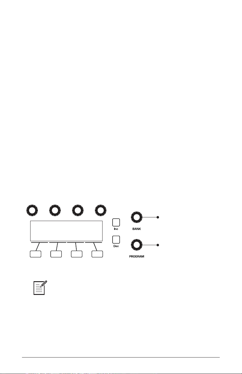
7. Use the bank and program knobs to scroll through the factory sounds.
You can also use Soft Knob 1 and Soft Knob 2 as well as inc and dec
buttons to scroll through the sounds in the currently selected bank.
Bank and Program controls
programmed into the touch slider and the mod wheel. While you’re trying out the
factory sounds, play with these performance controls and listen how the sound
changes. Each preset also has a pre-programmed sequence. To hear it, press the
play button in the seq section.
Pro 3 User’s Guide
Each of the factory presets has interesting and useful modulation functions
Setting Up the Pro 3
5
Page 18
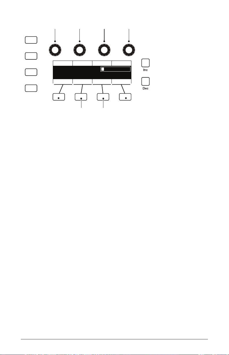
Using the Main Display
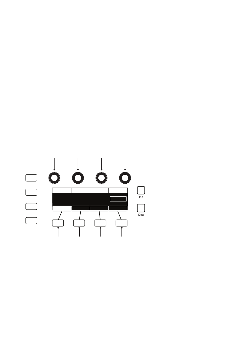
soft knob 1
parameter 1
soft knob 2
parameter 2
soft knob 3
parameter 3
soft knob 4
parameter 4
soft button 1
menu tab 1
soft button 2
menu tab 2
soft button 3
menu tab 3
soft button 4
menu tab 4
Write
Compare
Global
Play List
CUTOFF
Cuto DriveResonance Filter Type
RESONANCE
60 2060
DRIVE Filter Type
Env AmtFilter Env AmtFilter Misc ADSR
Ladder
The most frequently used controls on the Pro 3 are on its front panel. But
there are many additional controls (as well as numeric display of values)
visible in its main display.
For example, adjusting a knob or switch in the oscillators section
reveals the tuning, shape, and level menus in the display. The display
also reveals parameters not found on the front panel such as osc slop and
wave reset (in Tab 2). You can select and edit these additional param-
eters using the four Soft Knobs and Soft Buttons located above and below
the display.
The Soft Knobs are for dialing in values. The Soft Buttons select
between various menu tabs.
The Main Display
6
Using the Main Display
Sequential
Page 19
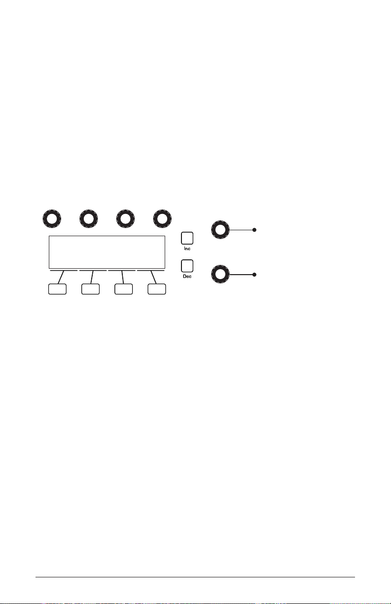
Sound Banks
U1
PRO 3 LEAD
P1
Turn to scroll through
User and Factory banks
Turn to scroll through
programs 1-128 in each bank
BANK
PROGRAM
The Pro 3 contains a total of 1024 programs. Banks U1-U4 are user
banks that can be overwritten. Banks F1-F4 are factory banks that are
permanent. As shipped, user banks U1-U4 are identical to permanent
factory banks F1-F4. Each bank has 128 programs (multiplied by 4
banks = 512 programs each). You can edit the programs of either bank,
but you can only save them to user banks U1-U4.
Banks of non-rewritable, permanent sounds are included so that they are
always available, to be used as is, or as templates for new sounds of your
own. It’s easy to design a new sound by tweaking an existing one.
Bank and Program controls
Selecting Programs
Use the bank and program knobs to select and recall programs.
To choose a program:
1. Turn the bank knob to select the bank you want.
2. Turn the program knob to select a program within that bank.
Pro 3 User’s Guide
Sound Banks
7
Page 20

Editing Programs
Write
Compare
Global
Play List
CUTOFF
Cuto DriveResonance Filter Type
RESONANCE
60 2060
DRIVE Filter Type
Env AmtFilter Filter TypeFilter Misc ADSR
Ladder
When editing a program
press to hear the saved
version for comparison
Because the majority of the sound-shaping controls of the Pro 3 appear on its
front panel, editing an existing program is simple: turn a knob and listen to
its effect. Keep turning knobs and pressing buttons. If you like what you’ve
created, save the program by pressing the write button twice. (See “Saving a
Program” on page 10 for more options when you save.)
The rotary controls on the front panel are a mixture of rotary encoders
(which have no position indicator) and potentiometers or “pots,” which
have a position indicator and a nite travel range from left to right. You
can choose between three different modes that determine how the synth
reacts when you edit its parameters with a pot. For details, see page
98.
Comparing an Edited Program to its Original State
When editing a program, it’s often useful to compare its edited state to
its original state to evaluate your edits.
To compare an edited program to a saved version:
1. Edit a program, then press the compare button.
2. Play the keyboard to hear the saved version of the sound.
3. To disable the compare function and return to the edited sound, press
Compare button
Editing Programs
8
the compare button again to turn it off. Programs can’t be written while
in compare mode.
Sequential
Page 21
It’s also useful to be able to check the value of a parameter for reference.
Write
Compare
Global
Play List
CUTOFF
Cuto DriveResonance Filter Type
RESONANCE
60 2060
DRIVE Filter Type
Env AmtFilter Filter TypeFilter Misc ADSR
Ladder
Revert
Show
Misc Params
Paraphonic
Press the Show button
and turn any knob to
see its current setting
without changing it.
Normally, to make a parameter value appear in the display, you have to
turn the parameter’s knob — which will change the parameter value. But
there is a way to do this without changing the value:
To check the value of a parameter without changing it:
1. Press the show button.
2. Turn any parameter knob. The value appears in the display.
3. To return to normal operation, press the show button again to disable it.
Using the Show button to display a parameter value
Creating a Program from Scratch
An existing program can be very useful as a jumping off point for new
sounds. But it’s also useful (and educational) to create a new sound from
scratch. The Pro 3 makes this easy by providing a “basic preset” that you
can quickly recall at any time. This preset is very simple, with a single
oscillator as its basis.
To recall the basic program:
Pro 3 User’s Guide
1. Press the global button.
2. Use Soft Knob 1 to scroll through the commands and select basic
program in the display menu.
3. Press soft button 1 (write now). The current sound settings are reset to
the basic program.
4. Press the global button again to return to normal operation. From here
you can begin creating your own sound using the basic program as a
starting point.
Editing Programs
9
Page 22

You can also recall the Basic Program by simultaneously pressing the trans-
pose down and the touch slider’s latch button.
Chapter 3 provides a selection of simple sound design tutorials. It’s designed
to give you a basic working knowledge of how to use the Pro 3 to make your
own sounds. See “Chapter 3: Programming the Pro 3” on page 104.
Saving a Program
If you’ve created a sound that you like, you’ll probably want to save it.
Saving a program overwrites a previously saved program. Sound designers often save many incremental versions of a program as they continue
to rene it. These intermediate versions often make good jumping off
points for new sounds.
To save a program to the same preset location:
1. Press the write button. Its LED begins blinking.
2. Enter a name for the program using the appropriate Soft Knobs and
Soft Button. (See the illustration that follows for their functions.)
3. Press the write button again. Its LED stops blinking and the program is
saved.
To save a program to a different location:
1. Press the write button. Its LED begins blinking.
2. Turn the bank or program knobs (or Soft Knob 1 and Soft Knob 2) to
select a new location. You can only save to banks U1-U4.
3. Enter a name for the program using the appropriate Soft Knobs and
Soft Buttons. (See the illustration that follows for their functions.)
Press the write button again. Its LED stops blinking and the program is
saved.
Saving a Program
10
Sequential
Page 23
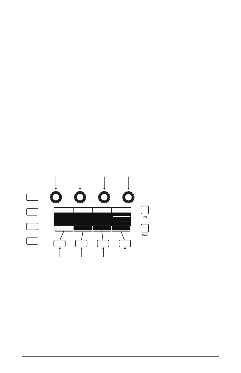
Writing to Bank:1 Program:1 A:
uper Bass
Hit ‘Write’ to Save Prog
Write Bank Write Prog Select Char Edit Char
S
Key AssignInsert Char Delete Char
select bank
insert character delete character
select program select character edit character
Write
Play List
Global
Compare
Saving a Program
Canceling Save
Sometimes you may want to cancel saving a program before you
commit.
To cancel the save process before you commit:
• If the write button LED is ashing, press the global button. The write
LED stops ashing and saving is canceled. You can return to editing if
you want.
Comparing Before You Save
Before saving a program to a new location, it’s a good idea to listen to the
program in the target location to make sure you really want to overwrite it.
To evaluate a program before you overwrite it:
1. Get ready to save by pressing the write button. It starts ashing.
2. Press the compare button. Its LED lights up.
3. Use the bank and program knobs to navigate to the sound you want to
audition and play the keyboard to hear the sound in the target location.
4. If you don’t want to overwrite that location, use the Bank and Program
knobs to select other possible locations to audition.
Pro 3 User’s Guide
Saving a Program
11
Page 24
5. Once you have found a location to overwrite, press the compare button
again to turn it off. (Programs can’t be written while in compare mode.)
6. The write button is still ashing and ready to save. Press write and the
sound is saved.
7. Alternatively, if you want to cancel saving and continue editing, press
the global button. Saving is canceled.
You can use the global button to set the program that appears when you
power on the Pro 3. Simply use the bank and program knobs to nd the program you
want, then press the global button twice. That program is now the default program on
start up.
Using Paraphonic Mode
The Pro 3 was designed primarily as a monophonic instrument. But we
added a 3-voice paraphonic playback mode for extra performance power.
In this mode, the three oscillators can be triggered independently, each
with its own amplier envelope. (However, the lter and its envelope are
shared between the three oscillators.) This gives you the ability to play
chords of up to 3 notes.
Make sure to select a waveshape for oscillator 3 since it’s possible to set this
oscillator to off. Each oscillator is triggered with an envelope set by the VCA shape.
Show
Write
Compare
Global
Play List
Cuto DriveResonance Filter Type
CUTOFF
60 2060
RESONANCE
Ladder
DRIVE Filter Type
Env AmtFilter Env AmtFilter Misc ADSR
Press the Paraphonic
button to enable
3-voice paraphonic mode.
Using Paraphonic Mode
12
Revert
Misc Params
Paraphonic
Sequential
Page 25

To enable paraphonic playback:
1. Press the paraphonic button.
2. Turn up the levels of all three oscillators in the mixer.
3. Play some chords.
4. Adjust the Octave and oscillator waveshapes as necessary.
With clever programming you can create complex sounds that work well in
paraphonic mode. Add a bit of pulse width modulation or chorused delay to create
interesting string and pad sounds.
Exploring the Pro 3 in Greater Depth
Before you explore the sound creation possibilities of the Pro 3, we’d
like to point you toward a few things that will help you tailor it to your
needs. The better you know it, the more you’ll get out of it.
First, read “Global Settings” on page 96. There are many useful
settings and functions found in the Global menu that will affect the
overall behavior of your Pro 3, including tuning, MIDI connections,
calibration, and more. In particular, read about Pot Modes and determine
which works best for you when you’re editing sounds.
Also, in “Rear Panel Connections” on page 2 read about the various
connectors on the back of your Pro 3 and how you can use its various
pedal, audio, MIDI, and USB inputs and outputs.
Finally, be on the lookout for tips and notes scattered throughout this
manual to gain a better working knowledge of the Pro 3. We wish you
many hours of musical exploration!
Pro 3 User’s Guide
Exploring the Pro 3 in Greater Depth
13
Page 26
Chapter 2: Pro 3 Controls
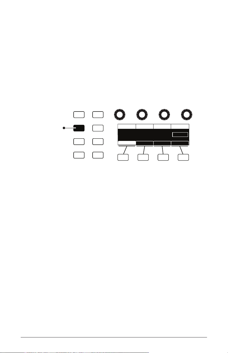
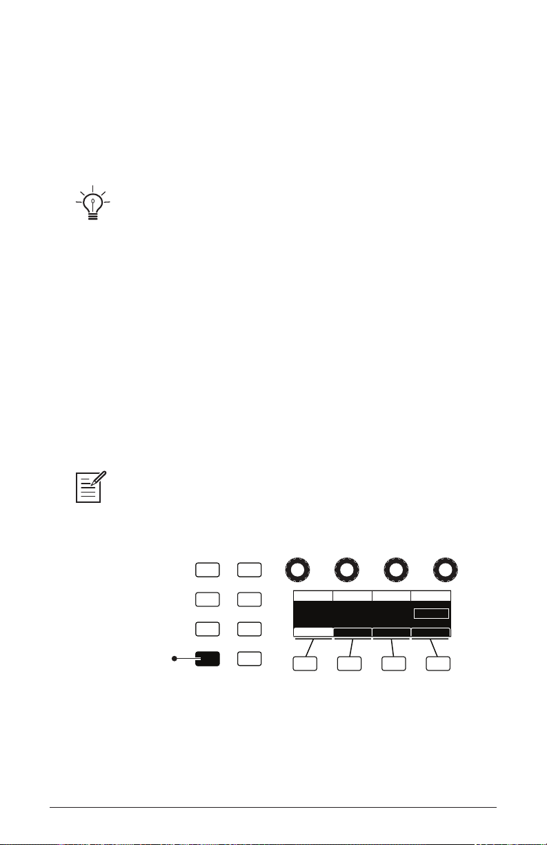
soft knob 1
parameter 1
soft knob 2
parameter 2
soft knob 3
parameter 3
soft knob 4
parameter 4
soft button 1
menu tab 1
soft button 2
menu tab 2
soft button 3
menu tab 3
soft button 4
menu tab 4
Write
Compare
Global
Play List
CUTOFF
Cuto DriveResonance Filter Type
RESONANCE
60 2060
DRIVE Filter Type
Env AmtFilter Env AmtFilter Misc ADSR
Ladder
This chapter explains all of the controls on the Pro 3, section by section.
As explained in Chapter 1, the most frequently used Pro 3 controls are
located on its front panel, with additional controls (as well as numeric
display of values) visible in its main display.
Adjusting a knob or switch in the Mixer section reveals the three oscillator level parameters and noise level parameter in the display. The
display also reveals additional parameters not found on the front panel
such as external input level, gate threshold, and more. You can select
and edit these additional parameters using the four Soft Knobs and Soft
Buttons located above and below the display.
The Soft Knobs are detented encoders for dialing in values. The Soft
Buttons select between various menu tabs.
The Main Display
14
Chapter 2: Pro 3 Controls
Sequential
Page 27
Oscillators
PITCH
SHAPE SHAPE MOD SYNC
PITCH SHAPE SHAPE MOD SYNC
PITCH SHAPE SHAPE MOD LOW FREQ
OSCILLATORS
OCTAVE
-1-2+1
+2
-1-2+1
+2
-1-2+1
+2
OCTAVE
OCTAVE
1
1
1
OSC 1OSC 2OSC 3
triangle
sawtooth
pulse/square
Oscillators generate the raw building blocks of the Pro 3’s sound by
producing waveforms, each of which has its own sound character based
on its harmonic content. The Pro 3 has two analog, voltage-controlled
oscillators and one digital wavetable oscillator.
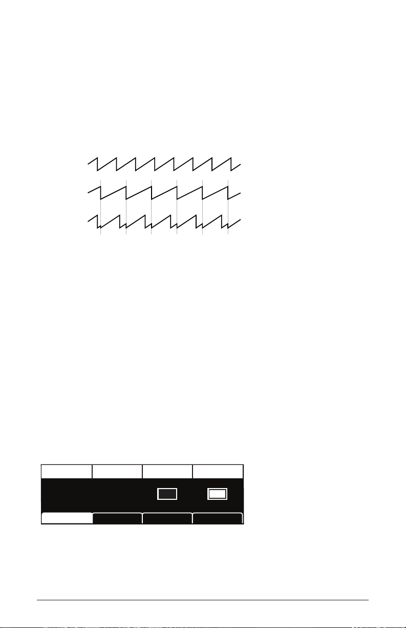
Oscillators 1 and 2 generate triangle, sawtooth, and pulse waves. You can
vary the “pulse width” of these waveshapes using the shape mod parameter. This allows for a variety of different waveshapes and timbres.
Shape Mod
value: 0
Oscillator pulse width (pulse wave)
Oscillator 3, because it’s digital, generates not only triangle, sawtooth,
super saw, and pulse waves but also complex, wavetable-derived wave
shapes.
The Oscillators section
Shape Mod
value: 254
Pro 3 User’s Guide
Oscillators
15
Page 28

To listen to the oscillators:
1. Press the global button.
2. Use Soft Knob 1 to navigate to the basic program command, then press
Soft Button 1 (write now).
3. In the basic program, only Oscillator 1 is audible. (The levels of Oscillators 2 and 3 are set to zero by default.)
4. Hold down a note on the keyboard and in the oscillators section,
turn the shape knob left and right to hear the waveshape change from
triangle to sawtooth to pulse. (Sawtooth is selected by default in the
basic program.)
5. With a specic waveshape selected, turn the shape mod knob and listen
to how the timbre of the waveshape changes. Note that when using
shape mod with the pulse wave, it’s possible to make the pulse width so
narrow that the sound “disappears.”
6. Be aware that on Oscillator 3, when super saw is selected as the waveshape (refer to the display to see the name of the waveshape), shape
mod controls the detuning of the Super Saw wave.
7. Turn up the level of Oscillator 2 in the Mixer and experiment with
setting each oscillator to a different waveshape. Experiment with the
pitch knob on the oscillators and notice how slightly detuning the oscil-
lators in relation to each other creates movement and thickness in their
combined sound. Try tuning one oscillator to a interval such as a third,
a fth, or a sixth.
8. Experiment with the octave knob on the oscillators and notice how
setting each oscillator to different octave inuences their combined
sound. This is especially true when using all three oscillators together.
9. Choose one of the three lter types and rotate the lter’s cutoff and
resonance knobs to see how this affects the sound of the oscillators.
10. With Oscillator 1 and 2 on, press the sync button on Oscillator 1, and
set it’s octave to 5. Then rotate the pitch knob on Oscillator 1 while
you hold a note. This is the classic hard sync sound that you’ve probably heard before. Instead of rotating the pitch knob by hand, you can
use the modulation matrix to route an envelope to Oscillator 1 to sweep
the oscillator’s pitch and create this effect each time you play a note.
You’ll learn more about the mod matrix in “Modulation” on page 46.
Oscillators
16
Sequential
Page 29

Exploring Oscillator 3
Because Oscillator 3 is a digital wavetable oscillator, it generates a variety of waveshapes. In addition to the standard, static waveshapes of sine,
sawtooth, super saw, and pulse waves, it provides 32 wavetables, each
with 16 different waves within that table.
Once you select one of the 32 wavetables with the shape knob, you
can then select a wave within the wavetable using the shape mod knob.
When you turn the shape mod knob, you’ll hear the waveshapes morph
smoothly from one to the next as the Pro 3 interpolates between them.
If you select one of the 32 wavetables, you can then select a specic
static wave. Or, if you use an LFO or the modulation matrix to control
shape mod, you can sweep through the selected table’s 16 waves to create
timbres that shift and evolve in interesting ways.
To listen to Oscillator 3:
1. Press the global button. Use Soft Knob 1 to navigate to the basic
program command, then press Soft Button 1 (write now).
2. In the basic program, only Oscillator 1 is audible. The levels of Oscillators 2 and 3 are set to zero in the Mixer by default.
3. In the mixer section, turn down the level of Oscillator 1 and turn up the
level of Oscillator 3.
4. Play and hold a note on the keyboard. In the oscillators section, turn
the shape knob on Oscillator 3 to select one of the 32 wavetables. The
rst choices are sine, sawtooth, super saw, and pulse, after that are
wavetables 1-32
5. Turn the shape mod knob to select a waveshape within the currently
selected wavetable. When you turn the knob, you’ll hear the waveshapes morph smoothly from one to the next.
Pro 3 User’s Guide
Oscillators
17
Page 30

To use an LFO to sweep through the waves in a wavetable:
1. Use the shape knob on Oscillator 3 to select one of the 32 wavetables.
2. In the lfo section, press the lfo 3 button, then the destination button.
3. In the display, choose osc 3 shapemod as the destination.
4. Hold down a note on the keyboard and listen as you set the frequency
and amount of LFO 3 modulation as desired. Higher frequency settings
sweep through the wavetable faster. Higher amount settings sweep
though a wider range of waves in the wavetable.
Oscillator Parameters (Front Panel)
Shape: Selects the waveshape generated by the oscillator. Oscillators 1
and 2 produce triangle, sawtooth, and pulse analog waveshapes. These
waveshapes are continuously variable. Oscillator 3 produces triangle,
sawtooth, super saw, and pulse waves, plus 32 wavetables containing 16
waves each.
Octave: Sets the base frequency of an oscillator over a 5-octave range. The
global master coarse and master fine settings affect the pitch of the
oscillators. See “Global Settings” on page 119 for more information.
Pitch: -700...+699—Fine tune control with a range of 7 semitones (a
major 5th) up or down. The 12 o’clock position is centered.
Shape Mod: On Oscillator 1 and 2, this changes the “pulse” width of the
selected waveform, which modies its harmonic content and timbre. To
generate a square wave when pulse is selected as the waveform, set this
parameter to 0. On Oscillator 3, this knob selects a waveshape within the
currently selected wavetable. If super saw is selected as the waveshape,
shape mod controls the thickness (detuning) of the Super Saw.
Applying waveshape modulation using an LFO or other modulation source in
the mod matrix is a great way to add movement to a sound.
Oscillators
18
Sequential
Page 31
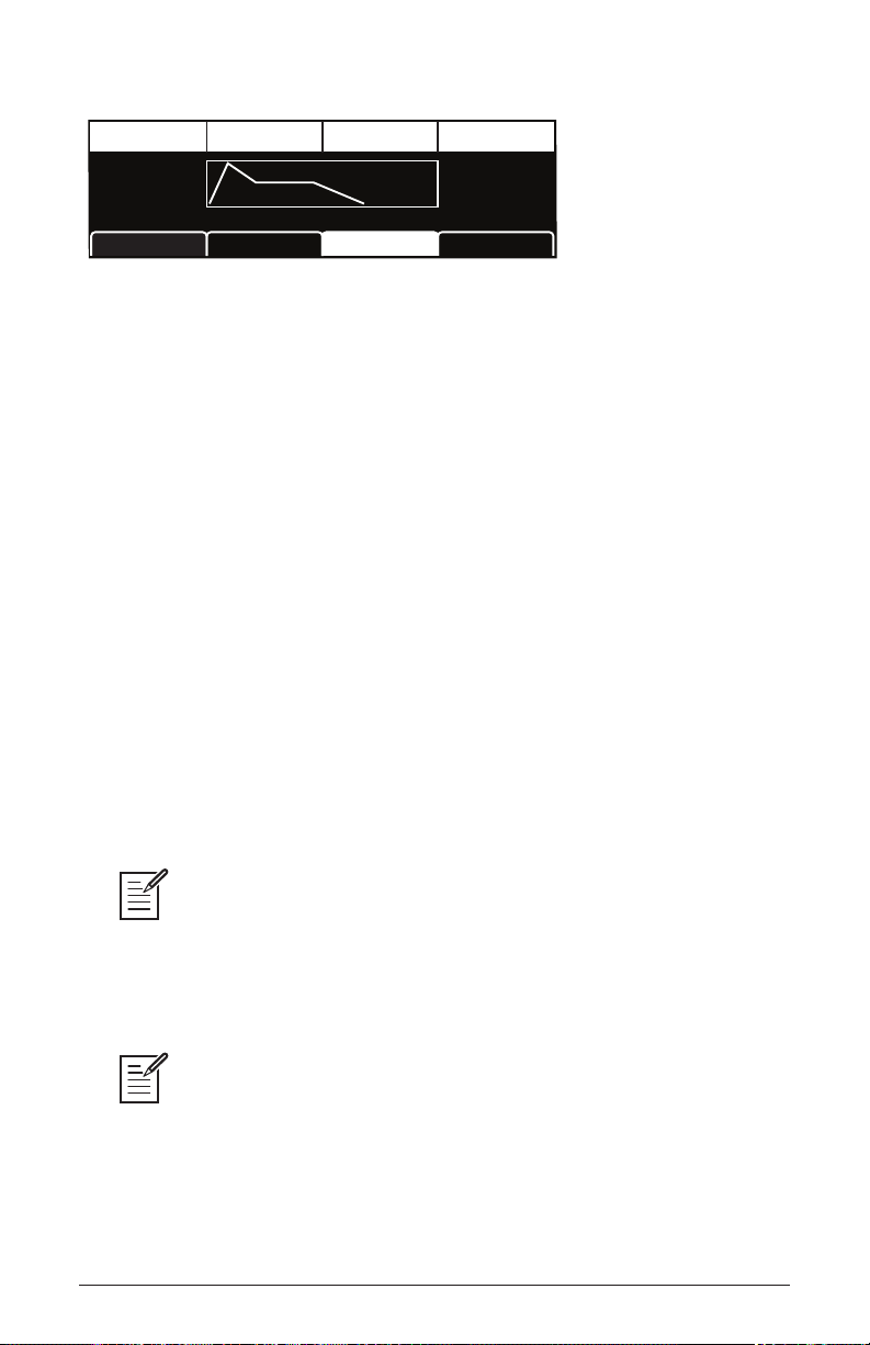
Sync: Off, On—Turns on oscillator hard sync. When an oscillator is hard
synced, its wave cycle is slaved to another oscillator’s wave cycle and is
forced to reset each time the master oscillator’s wave cycle restarts. This
causes the slaved oscillator to create harmonically complex waveforms
— particularly when the slave oscillator’s pitch is set higher than the
master oscillator’s pitch. See page 110 to learn how to set up a classic
oscillator hard sync sound.
Oscillator 1
Oscillator 2
Oscillator 1
synced to
Oscillator 2
Oscillator hard sync
Low Freq: Turns Oscillator 3 into an LFO (low frequency oscillator) so that
it can be used for modulation. Since Oscillator 3 is a wavetable oscillator,
the variety of waveshapes it produces is far greater than LFOs 1-3 and it
can be used to create many interesting modulation effects.
Additional Oscillator Parameters (Display Menus)
Additional oscillator parameters are accessible through the menus in the
main display. To see these menus, adjust any control in oscillators section
of the front panel. The parameters explained below do not appear on the
front panel.
TAB 1 - Osc Tuning
Frequency SyncFine Tune Key Follow
FREQUENCY
Key Follow: Off, On—When on, the oscillator tracks the keyboard or note
data received via MIDI. When off, the oscillator plays at its base frequency
setting, though its pitch may be affected by modulation from other sources.
Pro 3 User’s Guide
0-1
FINE TUNE
SYNC
Osc1 LevelOsc1 Tuning Osc1 MiscOsc1 Shape
KEY FOLLOW
Oscillators
19
Page 32

TAB 2 Osc Shape
Shape Wave ResetShape Mod Osc Slop
SHAPE
0 5-1
SHAPE MOD
WAVE RESET
Osc1 LevelOsc1 Tuning Osc1 MiscOsc1 Shape
OSC SLOP
Wave Reset: Off, On—(In the osc1 shape tab in the display) When Wave
Reset is off, the Pro 3 oscillators are free running. That is, the oscillators
are running whether a note is being gated on or not. When the amplier
envelope is set for a fast attack, this can cause a soft, but detectable, pop
or click at the beginning of a note because the note might be gated on
at a point in the wave’s cycle other than a zero crossing. The rst cycle
to play might be truncated. For some sounds, like monophonic basses,
this may actually be desirable. It adds a bit of randomness to the attack
that can make it sound more organic. When wave reset is on, the wave is
always reset to zero (the start of its cycle) when a note is triggered.
Osc Slop: 0…127—Adds random detuning to add or enhance the
natural pitch drift of the chosen oscillator. Vintage analog synthesizers all
had a certain amount of natural pitch drift which added to the warmth of
their sound. Smaller amounts of oscillator slop are subtle and add a more
organic feel. Larger amounts create a pronounced “out of tune” effect.
TAB 3 - Osc Level
Osc 1
0 0127
OSC 1
SHAPE MOD
WAVE RESET
Osc1 LevelOsc1 Tuning Osc1 MiscOsc1 Shape
Osc Level: 0…127—Sets the output level for the selected oscillator.
When using all three oscillators at once, especially with high levels of
resonance or drive, it may be necessary to reduce their levels to avoid
distortion (unless desired).
Oscillators
20
OSC SLOP
Sequential
Page 33

TAB 4 - Osc Misc
Glide Rate
0
GLIDE RATE
Osc1 LevelOsc1 Tuning Osc1 MiscOsc1 Shape
Glide Rate: 0...127—Sets the oscillator glide (portamento) amount.
Glide causes the pitch of a note to glide smoothly up or down from the
pitch of the previously played note. It can be set independently for each
oscillator. Low values are shorter/faster. The glide switch must be on to
hear t he effect of glide rate. For a detailed explanation, see “Glide” on
page 83.
Mixer
The Mixer section is where you set the levels of the various sound
generators on the Pro 3. These include oscillators 1-3, the noise generator, and an external input when connected to the rear panel input of the
Pro 3. You must turn up at least one of these sources in order to make
sound with the Pro 3. Alternatively, when using Low-pass 1 or Low-
pass 2, you can make the lter generate its own sine wave by turning up
resonance all the way so that it self-oscillates. The State-Variable lter
doesn’t self-oscillate.
Rather than limit the outputs of the Pro 3 to keep the instrument from clipping, we allow you to adjust levels at various points in its signal path. This gives you
the option of “overloading” things in interesting ways, if you wish to do so. If not, try
reducing the levels of the oscillators in the mixer section, turning down the drive and
resonance parameters in the Filter section, or the amount parameter in the Amp Enve-
lope section.
Pro 3 User’s Guide
Mixer
21
Page 34

OSC 1 LEVEL
OSC 2 LEVEL
EXT AUDIO
NOISE
OSC 3 LEVEL
MIXER
The Mixer section
Mixer Parameters (Front Panel)
Osc 1 Level: 0...127—Sets the output level of oscillator 1.
Osc 2 Level: 0...127—Sets the output level of oscillator 2.
Osc 3 Level: 0...127—Sets the output level of oscillator 3.
Ext Audio: 0...127—Sets the output level of an external signal connected
to the audio in jack on the rear panel of the Pro 3.
Noise: 0...127—Sets the output level of the noise generator.
22
Mixer
Sequential
Page 35

Additional Mixer Parameters (Display Menu)
Additional Mixer parameters are accessible through the menus in the
main display. To see these menus, adjust any control in mixer section of
the front panel. The parameters explained below do not appear on the
front panel.
TAB 2 - Ext in
Input Level In Gate ThreshInput Gain
INPUT LEVEL
Input Gain: 0...127—Boosts the input level of any signal connected to
127 00
INPUT GAIN
IN GATE THRESH
Ext In EnvMixer LPF MiscExt In
the audio in connector on the rear panel of the Pro 3. This is useful for
increasing the gain of low-level output devices such as guitars.
In Gate Thresh: 0...127—Sets the threshold above which external
input signals will trigger the Pro 3’s. Triggering from an external audio
input allows you to drive the Pro 3’s Sequencer steps with guitars, drum
machines and other devices.
TAB 3 - Ext in Env
Input Attack Input Release
INPUT ATTACK
Input Attack: 0...15—Sets the attack speed of the envelope follower. Use
this to ne tune the response of the envelope follower when triggering
the Sequencer from an external device connected to the audio in jack on
the rear panel of the Pro 3.
00
INPUT RELEASE
Ext In EnvMixer LPF MiscExt In
Input Release: 0...127—Sets the release speed of the envelope follower.
Use this to ne tune the response of the envelope follower when triggering the Sequencer from an external device connected to the audio in jack
on the rear panel of the Pro 3.
Pro 3 User’s Guide
Mixer
23
Page 36

Filters
The Pro 3 has three different lters, each of which has its own unique
character:
• low-pass 1 - 4-pole ota is a 4-pole, 24 db-per-octave resonant lter
based on the Sequential Prophet-6 lter. It can self-oscillate (generate a
sine wave) when resonance is set to its maximum.
• low-pass 2 - 4-pole ladder is a classic 4-pole, 24 db-per-octave resonant
transistor ladder lter. It can self-oscillate when resonance is set to its
maximum
• state-variable - 2-pole ota is a 2-pole, 12 db-per-octave lter based on
the Sequential OB-6 lter. It features low-pass, band-pass, high-pass,
and notch operation. The State-Variable lter cannot self-oscillate.
Another characteristic of the State-Variable lter is that increasing the
amount of resonance does not decrease the amount of low-frequencies
(bass). On Low-pass 1 and Low-pass 2, increasing the amount of reso-
nance de-emphasizes low frequencies. The bp and state controls apply
only to the State-Variable lter.
The differences between these lters can be subtle or dramatic, depending
on their individual settings, the amount of lter resonance applied, and
other factors. The function of the lters is to subtract frequencies from
the sound produced by the oscillators, noise generator, and/or external
audio input, thereby changing the overall harmonic content of the synth’s
sound. This change is varied over time using the Filter Envelope to
produce more dynamic timbres.
24
Filters
Sequential
Page 37

CUTOFF
DRIVE
BP
LP
NOTCH
LOW-PASS 1 LOW-PASS 2 STATE-VARIABLE
4-Pole OTA 4-Pole Ladder 2-Pole OTA
HP
RESONANCE
STATE
FILTER
Press one of these buttons to select the lter type
To hear the effect of the lter:
1. Recall the Basic Program by pressing the global button and using Soft
Knob 1 to navigate to the basic program command, then press Soft
Button 1 (write now).
2. Press the low-pass 1 button to select this lter.
3. Hold down a note and rotate the lter’s cutoff knob. Notice how it cuts
the high frequencies as you rotate counter-clockwise, making the sound
of the oscillator less bright. If you turn the cutoff knob fully counter-
clockwise you’ll lter out all frequencies and hear nothing.
4. Return the cutoff knob to its halfway position, hold down a note again
then turn the resonance knob about halfway up.
5. Rotate the lter’s cutoff knob again and listen to the sound change as
a band of frequencies near the cutoff is amplied. This how to create a
classic resonant lter sweep.
In the previous example, you controlled the lter cutoff by hand. In most
cases, you will use the Filter Envelope to do this. To learn more about the
Filter Envelope see page 31.
Pro 3 User’s Guide
Filters
25
Page 38

Exploring the State-Variable Filter
As its name suggests, the State-Variable lter can change its operational
mode/state from low-pass, to notch, to high-pass, with a separate bandpass mode that you can activate using the bp (band-pass) button. This
makes the State-Variable lter very versatile.
Exploring the State-Variable lter:
1. Press the global button and use Soft Knob 1 to navigate to the basic
program command, then press Soft Button 1 (write now).
2. Press the state-variable button to select this lter.
3. Turn the state knob all way to the left so that the lter is set to lp (low-
pass mode).
4. Hold down a note and rotate the lter’s cutoff knob. Notice how it cuts
the high frequencies as you rotate counter-clockwise, making the sound
less bright.
5. Turn the lter’s state knob to notch and rotate the cutoff knob again.
Listen to the effect as the lter cuts a band of frequencies centered
around the cutoff frequency.
6. Now turn the lter’s state knob to hp (high-pass) and rotate the cutoff
knob again. Listen to the effect as the lter removes the low-frequencies from the sound.
7. Now press the bp (band-pass) button and rotate the cutoff knob again.
This time, the lter removes frequencies above and below the cutoff
frequency.
8. Finally, turn the resonance knob to it’s center positions and repeat steps
3-6 to hear the effect.
Note that there are many intermediate states between the lp, notch, and
hp settings. This is one of the reasons that the State-Variable lter is so
versatile.
Modulating the state-variable lter’s operating mode with an envelope or LFO
can create many unique and interesting sounds. Set the modulation source to lfo and
the destination to sv lp-n-hp.
Filters
26
Sequential
Page 39

Filter Parameters (Front Panel)
Filter Type Buttons: Low-Pass 1, Low-Pass 2, State-Variable—These
select the lter type. Low-Pass 1 is a 4-pole, 24 db per-octave resonant
lter based on the Sequential Prophet-6. Low-Pass 2 is a classic 4-pole,
24 db per-octave ladder lter. State-Variable is a 2-pole, 12 db per-octave
lter based on the Sequential OB-6, with low-pass, notch, high-pass, and
band-pass modes.
Drive: 0...127—Increases signal input to the lter, boosting volume and
adding harmonic saturation and warmth.
Cutoff: 0...164—Sets the lter’s cutoff frequency.
Resonance: 0...255—Emphasizes a narrow band of frequencies around
the cutoff frequency. High levels of resonance can cause the Low-Pass 1
and Low-Pass 2 to self-oscillate and generate its own pitch. The State-
variable lter does not self oscillate at the maximum resonance setting.
High levels of resonance can sometimes cause the Pro 3 outputs to clip. To
remedy this, reduce oscillator levels in the Mixer, or reduce the Amp Envelope’s
amount parameter.
State: LP, Notch, HP, BP—This knob selects the State-Variable lter’s
mode of operation. It transitions smoothly from low-pass to notch to
high-pass operation, allowing a blending of these modes. Band-pass
operation is selected with the bp switch. Each lter mode has its own
characteristic sound and function. As noted previously:
• Low-pass: passes frequencies below the cutoff frequency
• Notch: removes frequencies in a notch centered around the cutoff frequency
• High-pass: passes frequencies above the cutoff frequency
• Bandpass: passes a band of frequencies centered around the cutoff frequency
On the front panel, band-pass mode is selectable only through the bp on/off
switch. However, you can actually smoothly transition between normal and band-pass
operation by choosing sem-normal-bp as a modulation destination in the mod matrix.
BP: On, Off—Switches the State-variable lter to band-pass mode.
Pro 3 User’s Guide
Filters
27
Page 40

Additional Filter Parameters (Display Menus)
Additional Filter parameters are accessible through the menus in the
main display. To see these menus, adjust any of controls in filter section
of the front panel. The parameters explained below are the ones that
don’t already appear on the front panel.
TAB 2 - Filter Misc
LP-Notch-BP Key>LPF FRQBdPass-Notch Env Amt
LP-NOTCH-HP
Key>LPF Freq: 0...127—Sets the amount of modulation from the
BDPASS-NOTCH
028
KEY>LPF FREQ
ADSRFilter Env AmtFilter Misc
LADDER RES COMP
keyboard to the lter’s cutoff frequency. Any setting above zero means
that the higher the note played on the keyboard, the more the lter opens.
This is useful for adding brightness to a sound as higher notes are played,
which is typically how acoustic instruments behave. When set to zero,
keyboard lter tracking is off, meaning that lter frequency is unaffected by
playing higher or lower notes on the keyboard. When set to 127, the lter
will track in half-step increments, which can be useful if you are using
the lter to generate a pitch through self-oscillation.
Ladder Res Comp: On, Off—In a classic ladder lter, increasing the
amount of resonance decreases the amount of bass response. This parameter compensates for this by boosting bass frequencies as resonance is
increased on Low-Pass 2 Filter. This parameter is on by default.
28
Filters
Sequential
Page 41
TAB 3 - ADSR
Attack SustainDecay Release
A:25
D:36
S:52
ADSR Env AmtFilter MiscFilter
R:44
Attack: 0...127—Sets the attack time of the envelope. The higher the
setting, the slower the attack time and the longer it takes for the lter to
open from the level set with the lter cutoff knob to the level set by the
lter envelope amount. Percussive sounds typically have sharp (short)
attacks.
Decay: 0...127—Sets the decay time of the envelope. After a sound
reaches the lter frequency set at its attack stage, decay controls how
quickly the lter then transitions to the cutoff frequency set with the
sustain knob. The higher the setting, the longer the decay. Percussive
sounds, such as synth bass, typically have shorter decays (and a generous
amount of low-pass lter resonance).
Sustain: 0...127—Sets the lter cutoff frequency for the sustained
portion of the sound. The sound will stay at this lter frequency for as
long as a note is held on the keyboard.
Release: 0...127—Sets the release time of the envelope. This controls
how quickly the lter closes after a note is released.
The description of envelope behavior just given is true when the amount parameter is set to a positive value. But since this control is actually bipolar, it is possible to
set a negative amount of modulation. In this case, the envelopes are inverted and their
behavior changes. The best way to get a feel for the difference is to experiment with
both positive and negative settings of the amount parameter.
The cutoff frequency setting may limit the effect of the envelope on the lter. For
example, in low-pass lter mode , if cutoff is at its highest setting, a positive envelope
amount will have no effect on the lter since the lter is already completely open.
Pro 3 User’s Guide
Filters
29
Page 42

TAB 4 - Env Amt
Amount DelayVel On/O Env Loop
Amt:+25
Vel:On
Del:0
ADSR Env AmtFilter MiscFilter
Loop:O
Amount: -127...127—Sets the amount of modulation from the lter
envelope to the lter’s cutoff frequency. Any setting above zero means
that each time you strike a key, the lter envelope controls how the lter
opens and closes. Higher amounts more dramatically affect the cutoff
frequency. This control is bipolar. Positive settings produce standard
behavior. Negative settings invert the envelope.
Velocity On/Off: On, Off—Allows key velocity to inuence lter cutoff
frequency. If on, the harder you play, the more the lter will open and the
brighter the sound will be. If off, key velocity will not affect the lter.
This control allows for more touch-sensitive sounds.
Delay: 0...127—Sets a delay between the time the envelope is triggered
and when the Attack and subsequent stages occur.
Loop: Off, On—When on, the Delay, Attack, and Decay segments of
the envelope repeat. Sustain still affects the level at which the Decay
segment ends, but instead of sustaining at a xed level while a note is
triggered, Delay, Attack, and Decay loop until the note is turned off. The
Release segment begins when the note is released, just as it does when
Repeat is off.
30
Filters
Sequential
Page 43
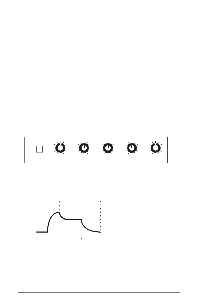
Filter Envelope
ATTACK DECAY SUSTAIN RELEASEAUX ENV AMOUNT
1 2
AUX
attack
decay
sustain
release
amplitude
time
note offnote on
delay
The Pro 3 lter has a dedicated, 5-stage envelope generator (attack,
decay, sustain, release, plus delay). The Filter Envelope is used to shape
the harmonic characteristics of a synthesized sound by giving you ltering control with these stages.
This is one of the most important aspects of a synthesized sound. Without
an envelope, the lters would be static and unchanging. They would stay
open or closed by a xed amount that wouldn’t change over the duration
of a sound. That’s not very expressive or interesting to listen to — and
it’s not how most real-world instruments behave.
In general, sounds produced by an acoustic instrument are brighter at
their beginning (the attack stage) and grow mellower as they die out (the
decay and release stages). In other words, their harmonic content changes
over time. This is exactly what the lter envelope is designed to emulate.
FILTER
VELOCITY ATTACK DECAY SUSTAIN RELEASE AMOUNT
Filter Envelope
A typical 5-stage DADSR envelope
Pro 3 User’s Guide
Filters
31
Page 44

To hear the effect of the Filter Envelope:
1. Press the global button and use Soft Knob 1 to navigate to the basic
program command, then press Soft Button 1 (write now).
2. Press the low-pass 1 button to select this lter type.
3. Hold down a note and rotate the lter’s cutoff knob to set it to
a value of 40 (refer to the main display to see its numeric value).
4. Play a note. At this point you may not hear anything because you’ve
closed the lter signicantly.
5. In the Envelopes section, turn the Filter Envelope’s amount knob to a
value of 50 (refer to the main display to see its numeric value).
6. Play a note. Notice how the sound has changed. The Filter Envelope is
controlling lter cutoff by the amount you set with the amount knob.
7. Repeatedly strike a note on the keyboard as you turn the Filter Envelope’s decay knob clockwise and counterclockwise. Notice how it
changes the sound as the note decays faster or slower after its initial
attack stage.
8. Now experiment with the Filter Envelope’s attack knob. Notice how
the attack becomes faster or slower.
9. Now hold down a note and experiment with the Filter Envelope’s
sustain knob. This controls how wide the lter stays open while you
hold down a key on the keyboard.
10. The Filter Envelope’s release parameter acts in conjunction with the
Amplier Envelope, so to hear its effect, rst set the Amp Envelope’s
release value to 75.
11. Now repeatedly strike a note on the keyboard as you turn the Filter
Envelope’s release knob clockwise and counterclockwise. Notice how
the note fades out faster or slower as you change the release value.
12. Continue experimenting with various Filter Envelope settings while
you adjust the Filter Envelope’s env amount knob. Notice how greater
amount settings amplify the effect of the envelope on the lter.
As noted above, the Filter Envelope and Amplier Envelope often work
in conjunction, with the Filter Envelope controlling how the lter opens
and closes and the Amplier Envelope controlling how the Amplier
controls the overall volume shape of the sounds you create. To learn
more about the Amplier Envelope, see page 35.
Filters
32
Sequential
Page 45

Envelope Parameters (Front Panel)
Attack: 0...127—Sets the attack time of the envelope. The higher the
setting, the slower the attack time and the longer it takes for the lter to
open from the level set with the lter cutoff knob to the level set by the
lter envelope amount. Percussive sounds typically have sharp (short)
attacks.
Decay: 0...127—Sets the decay time of the envelope. After a sound
reaches the lter frequency set at its attack stage, decay controls how
quickly the lter then transitions to the cutoff frequency set with the
sustain knob. The higher the setting, the longer the decay. Percussive
sounds, such as synth bass, typically have shorter decays (and a generous
amount of low-pass lter resonance).
Sustain: 0...127—Sets the lter cutoff frequency for the sustained
portion of the sound. The sound will stay at this lter frequency for as
long as a note is held on the keyboard.
Release: 0...127—Sets the release time of the envelope. This controls
how quickly the lter closes after a note is released.
Velocity On/Off: On, Off—Allows key velocity to inuence lter cutoff
frequency. If on, the harder you play, the more the lter will open and the
brighter the sound will be. If off, key velocity will not affect the lter.
This control allows for more touch-sensitive sounds.
Amount: -127...127—Sets the amount of modulation from the lter
envelope to the lter’s cutoff frequency. Any setting above zero means
that each time you strike a key, the lter envelope controls how the lter
opens and closes. Higher amounts more dramatically affect the cutoff
frequency. This control is bipolar. Positive settings produce standard
behavior. Negative settings invert the envelope.
Pro 3 User’s Guide
Filters
33
Page 46

Additional Filter Envelope Parameters (Display Menus)
Additional Filter parameters are accessible through the menus in the
main display. To see these menus, adjust any of the lter envelope controls
in the envelopes section of front panel. The envelope parameters are in
menu Tab 3 and Tab 4. The parameters explained below are the ones that
don’t appear on the front panel.
TAB4 - Env Amount
Amount DelayVel On/O Env Loop
Amt:+25
Vel:On
Del:0
ADSR Env AmtFilter MiscFilter
Loop:O
Delay: 0...127—Sets a delay between the time the envelope is triggered
(note on) and when the attack portion actually begins.
Loop: Off, On—When on, the Delay, Attack, and Decay segments of
the envelope repeat. Sustain still affects the level at which the Decay
segment ends, but instead of sustaining at a xed level while a key is
pressed, Delay, Attack, and Decay loop until the key is released. The
Release segment begins when the key is released, just as it does when
Repeat is off.
34
Filters
Sequential
Page 47

Amplier Envelope
VELOCITY ATTACK DECAY SUSTAIN RELEASE AMOUNT
ATTACK DECAY SUSTAIN RELEASEAUX ENV AMOUNT
1 2
FILTER
AUX
attack
decay
sustain
release
amplitude
time
note offnote on
delay
After passing through the lters, a synthesized sound goes into an
amplier, which controls its overall volume. The amplier has a
dedicated, 5-stage envelope generator (attack, decay, sustain, release,
plus delay) which is used to shape the volume characteristics of a sound
over time by giving you control over these stages. Along with the lter
envelope, this is one of the most important aspects of a synthesized
sound.
Without a volume envelope, the volume of a sound wouldn’t change
over the duration of a note. It would begin immediately, remain at its full
volume for its duration of the note, then end immediately when the note
was released. Again, that’s not very interesting sonically and it’s not typically how instruments behave in the real world.
To give you a real-world example, the main difference between the sound
of the wind and the sound of a snare drum is that they have very different
volume envelopes. Otherwise, they are essentially both white noise.
Wind has a relatively slow attack, a long sustain, and a long decay and
release. A snare drum has a sharp attack, no sustain, and very little decay
or release. But again, they are both fundamentally white noise.
AMP
VELOCITY ATTACK DECAY SUSTAIN RELEASE AMOUNT
ENVELOPES
Amplier Envelope
A typical 5-stage, DADSR envelope
Pro 3 User’s Guide
Amplier Envelope
35
Page 48

As noted previously, the Amplier Envelope often works in conjunction with the Filter Envelope, with the Filter Envelope controlling
how the lter opens and closes and the Amplier Envelope controlling how the Amplier controls the overall volume shape of the
sounds you create.
To hear the effect of the Amplier Envelope:
1. Press the global button and use Soft Knob 1 to navigate to the basic
program command, then press Soft Button 1 (write now).
2. Repeatedly strike a note on the keyboard as you turn the Amplier
Envelope’s attack knob clockwise. Notice how the attack becomes
slower and more gradual the further you turn the knob.
3. Reset the attack parameter to zero.
4. Next, repeatedly strike a note on the keyboard as you turn the Ampli-
er Envelope’s sustain to zero. Notice how it changes the sound so that
the sound no longer sustains even if you hold down the key. The only
sound you hear is the decay portion of the sound.
5. Now, with sustain still set to zero, repeatedly strike a note on the
keyboard as you turn the Amplier Envelope’s decay knob clockwise
and counterclockwise. Notice how it changes the sound as the note
decays faster or slower after its initial attack stage.
6. Reset the decay parameter to 127
7. Finally, with decay set to 127 and sustain still set to zero, repeatedly
strike a note on the keyboard as you turn the Amplier Envelope’s
release knob clockwise. Notice how the release becomes longer the
further you turn the knob.
8. Continue experimenting with various Amplier Envelope settings while
you also adjust the Filter Envelope to hear how these two controls
interact. You will understand how powerful the envelopes are and how
essential they are to designing sounds.
Amplier Envelope
36
Sequential
Page 49

Amplier Envelope Parameters (Front Panel)
Attack: 0...127—Sets the attack time of the envelope. The higher the
setting, the slower the attack time and the longer it takes for a sound to
reach its full volume. Pads typically have softer (longer) attacks. Percussive sounds have sharper (shorter) attacks.
Decay: 0...127—Sets the decay time of the envelope. After a sound
reaches its full volume at its attack stage, decay controls how quickly the
sound transitions to the level set with the sustain control. The higher the
setting, the longer the decay. Percussive sounds, such as synth bass, typically have shorter decays.
Sustain: 0...127—Sets the sustain level of the envelope. The higher the
setting, the louder the sustained portion of the sound will be. The sound
will stay at this level for as long as a note is held on the keyboard.
Release: 0...127—Sets the release time of the envelope. This controls
how quickly a sound dies out after a note is released.
Env Amount: 0...127—Sets the amount of modulation from the Enve-
lope to the VCA. In most cases you will probably want to set this fully
clockwise for maximum VCA volume. If you experience signal clipping,
try reducing the env amount.
To create a “gated VCA” effect, set the amount of the Amplier Envelope to
zero, route the LFO square wave to env vca amt with an amount setting of 127, and
hold a note.
Velocity On/Off: On, Off—Allows key velocity to inuence volume.
If on, the harder you play, the louder sound will be. If off, key velocity
will not affect the volume. This control allows for more touch-sensitive
sounds.
Pro 3 User’s Guide
Amplier Envelope
37
Page 50

Additional Amplier Parameters (Display Menus)
Additional Amplier Envelope parameters are accessible through the
menus in the main display. To see these menus, adjust any of the controls
in amp portion of the envelopes section of the front panel. The parameters
explained below are the ones that don’t appear on the front panel.
TAB 1 - VCA
Attack
127
VOLUME
VCA ADSR VCA Env AmtFXVCA
Volume: 0...127—Sets the volume of the currently active program.
Although the master output level of the Pro 3 is controlled by the frontpanel master volume knob, the volume parameter in this menu sets the
volume of an individual program. This is useful for ensuring that your
sounds have roughly the same volume from program to program.
TAB 4 - VCA Env Amount
Amount DelayVel On/O Env Loop
Amt: 127
Delay: 0...127—Sets a delay between the time the envelope is triggered
Vel: O
Del: 0
VCA ADSR VCA Env AmtFXVCA
Loop: O
(note on) and when the attack portion actually begins.
Loop: Off, On—When on, the Delay, Attack, and Decay segments of
the envelope repeat. Sustain still affects the level at which the Decay
segment ends, but instead of sustaining at a xed level while a note is
gated on, Delay, Attack, and Decay loop until the note is turned off. The
Release segment begins when the note is gated off, just as it does when
Repeat is off.
Amplier Envelope
38
Sequential
Page 51

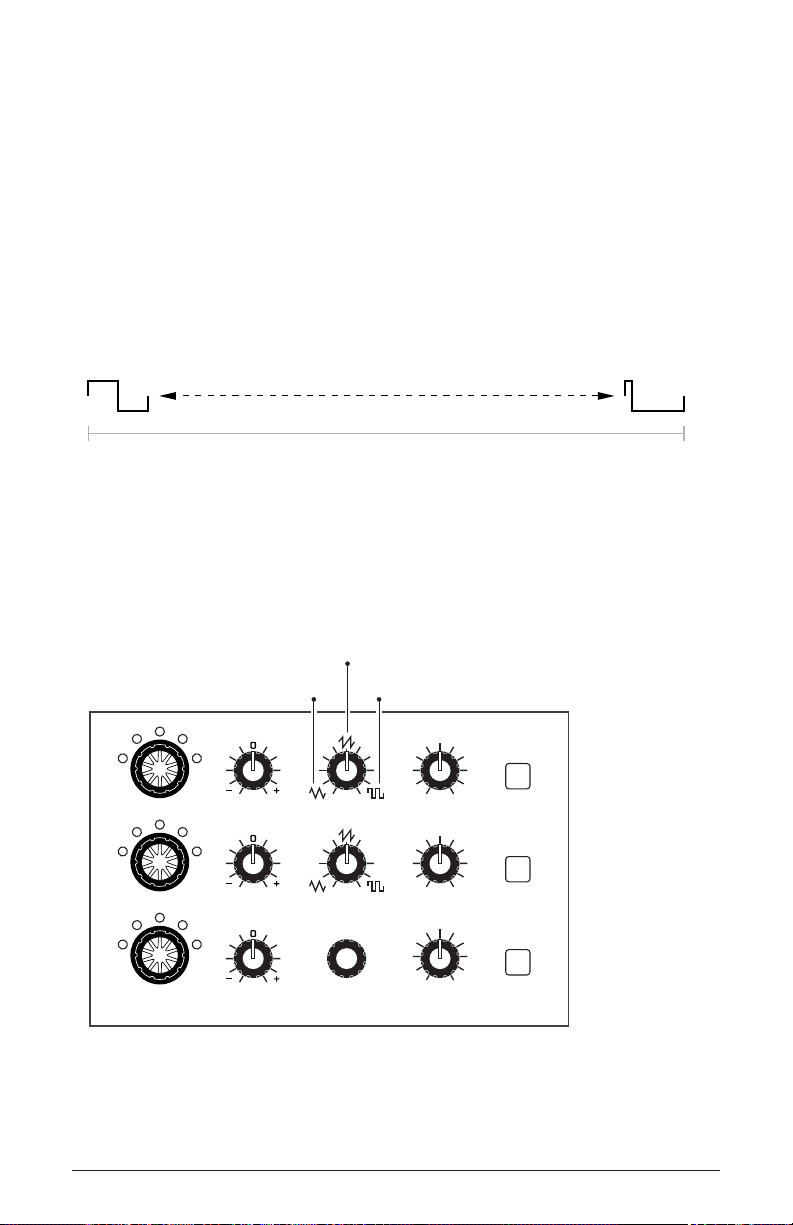
Auxiliary Envelopes
ATTACK DECAY SUSTAIN RELEASEAUX ENV AMOUNT
1 2
AUX
The Pro 3 has two additional 5-stage envelope generators (attack, decay,
sustain, release, plus delay). They are useful for creating modulation
that varies over time according to the shape of the envelope. Routing an
envelope to an oscillator’s frequency, for example, causes the oscillator’s
pitch to rise and fall according to the contour of the envelope.
As with all of the Pro 3’s envelopes, there are controls for modulating the
envelope amount using keyboard velocity. The Auxiliary Envelopes can be
routed to any of the modulation destinations in the mod matrix. In addition,
the Auxiliary Envelopes can repeat (loop) using the repeat function in the
aux envelopes display menu. This is useful for cyclical 4-stage modulation.
There are many ways to make creative use of the Auxiliary Envelopes:
• Route an Auxiliary Envelope to one of the oscillators’ coarse freq
parameter to create the classic “pitch blip” effect used in many synth
lead sounds.
• Route an Auxiliary Envelope to the lter’s cutoff parameter (in addi-
tion to the standard Filter Envelope) to create a more complex lter
envelope shape.
• Route an Auxiliary Envelope to one or more of the oscillators’ shape
parameter to make their timbre evolve according to envelope’s contour.
• Route an Auxiliary Envelope with a fast attack and short decay to noise
level to add a percussive attack to a sound. (Noise should be set to zero
in the Mixer.)
Actually, any of the Pro 3’s envelopes can be routed to any destination (or multiple
destinations) using the modulation matrix. See “Modulation” on page 47 for more
information.
Auxiliary Envelopes
Pro 3 User’s Guide
Auxiliary Envelopes
39
Page 52

Auxiliary Envelope Parameters (Front Panel)
1/2 Buttons: Selects either Auxiliary Envelope 1 or Auxiliary Envelope 2
for editing.
Velocity: On/Off—This button enables keyboard velocity to modulate the
Envelope Amount.
Attack: 0...127—Sets the attack time of the envelope. The higher the
setting, the slower the attack time.
Decay: 0...127—Sets the decay time of the envelope. This controls how
quickly the value transitions from the attack level to the level set with the
sustain control. The higher the setting, the longer the decay.
Sustain: 0...127—Sets the sustain level of the envelope. It will stay at
this level for as long as a note is held on the keyboard.
Release: 0...127—Sets the release time of the envelope. This controls
how quickly the value transitions to zero after a note is released on the
keyboard.
Amount: -127...127—Sets the amount of modulation from the envelope
to the selected modulation destination. Higher amounts more dramatically affect the destination. This control is bipolar. Positive settings
produce standard behavior. Negative settings invert the envelope.
Auxiliary Envelopes
40
Sequential
Page 53

Additional Auxiliary Envelope Parameters (Display Menus)
Additional Envelope parameters are accessible through the menus in the
main display. To see these menus, adjust any of the controls in aux env
section of the front panel. The parameters explained below are the ones
that don’t appear on the front panel.
TAB 1 - Aux 1 Destination
Destination SustainDecay Release
O
DESTINATION
Aux 1 Env Amt VCA ENV AMTAux 1 ADSRAux 1 Dest
Destination: Various—Selects a modulation destination for the Auxiliary
Envelope. See “Appendix B:
Modulation Destinations” on page 120 for a list of possible destinations.
You can quickly assign an aux envelope to a destination by holding the aux env
button and turning a knob on the front panel. The currently selected aux envelope will
be assigned to the touched parameter.
TAB 3 - Aux 1 Env Amount
Amount DelayVel On/O Env Repeat
AMT: 127
Vel: O
Del: 0
Aux 1 Env Amt VCA ENV AMTAux 1 ADSRAux 1 Dest
Velocity On/Off: On, Off—Allows key velocity to inuence the mount of
modulation applied. If on, the harder you play, the more the Aux Envelope will affect the chosen modulation destination. If off, key velocity
will not affect the amount of modulation from the Auxiliary Envelope.
Delay: 0...127—Sets a delay between the time the envelope is triggered
(note on) and when the attack portion actually begins.
Pro 3 User’s Guide
Rept: O
Auxiliary Envelopes
41
Page 54

Loop: Off, On—When on, the Delay, Attack, and Decay segments of
the envelope repeat. Sustain still affects the level at which the Decay
segment ends, but instead of sustaining at a xed level while a key is
held down, Delay, Attack, and Decay loop until the key is released. (The
Release segment begins when the key is released, just as it does when
Repeat is off.)
Low Frequency Oscillators
The three LFOs are special-purpose oscillators that produce a frequency
that is typically below the range of human hearing (although these can
actually extend into the audio range if set to their maximum frequency).
The LFOs are typically used for periodic modulation such as vibrato
(periodic pitch modulation) and tremolo (periodic amplitude modulation). They can also be used as modulation sources for any of the many
modulatable parameters in the Pro 3.
The LFOs produce a variety of waveshapes, including triangle, sawtooth,
reverse sawtooth, square, and s&h (sample & hold/random). Though
most often used for low-frequency modulation, the Pro 3 LFOs can actually
function at speeds that extend into the audible range for extreme effects.
1 2 3
FREQUENCY AMOUNT
DESTINATIONSHAPE
LFO
The Low Frequency Oscillators
Low Frequency Oscillators
42
Sequential
Page 55

Triangle and Sample & Hold waves are bipolar. That is, their waveshape is
positive for half of their cycle and negative for the other half. In the case of
the triangle wave, this makes it possible to generate a vibrato that goes alter-
nately sharp and at in equal amounts on either side of a center frequency.
Random, also known as “sample and hold,” generates a series of random
values, each held for the duration of one cycle.
The square wave, sawtooth, and reverse sawtooth generate only positive
values. In the case of the square wave, this makes it possible to generate
natural-sounding trills.
Triangle
0
LFO waveshapes
Sawtooth
Square Sample & HoldSawtooth Reverse
The LFOs can be free-running or synced to the Arpeggiator, Sequencer, or
MIDI clock for tempo-synced effects such as lter sweeps, tremolo, and so on.
LFO Parameters (Front Panel)
Frequency: 0...150—Sets the frequency of the selected LFO from a
slow .022Hz to a fast 500Hz. This is affected by the clk sync (clock
sync) parameter as explained below.
Amount: 0...127—Sets the amount of LFO modulation routed to the
selected destination. Setting an amount here applies the selected modulation continuously. You can also use the modulation matrix to route an
LFO to additional destinations and use a different modulation amount if
you want.
Shape: Triangle, Sawtooth, Reverse Sawtooth, Square, S&H—This
button sets the waveshape of the selected LFO.
Destination: Various—Routes the selected LFO to one of the many
modulation destinations within the synthesizer. These appear in the
display. You can also use the modulation matrix to route an LFO to additional destinations.
Pro 3 User’s Guide
Low Frequency Oscillators
43
Page 56

There are many ways to make creative use of the LFOs:
• Route the LFO to the coarse freq parameter of the oscillators to create
vibrato (triangle wave) or random pitches (s&h/random wave).
• Route the LFO’s triangle wave to the lter’s cutoff parameter and use
a medium freq and amount setting to create a wah-wah effect, or use
a slow freq setting and low amount setting to create subtle harmonic
movement.
• Route the LFO’s square wave to the amplier’s amount parameter and
use a medium freq and amount setting to create a tremolo effect.
• Route an LFO to an oscillator’s shape parameter to make its timbre
evolve. This can be particularly interesting when using Oscillator 3
wavetables.
• Route the LFO’s triangle wave to the time parameter of the stereo delay
and use a slow freq and low amount setting to create a chorus effect.
Any LFO can be routed to any destination (or multiple destinations) using the
modulation matrix. See page 120 for a list of destinations.
Additional LFO Parameters (Display Menus)
Additional LFO parameters are accessible through the menus in the main
display. To see these menus, adjust any of the controls in lfo portion of the
front panel.
TAB 1 - LFO Shape
Shape SyncFrequency Amount
Triangle
LFO Shape
Frequency
LFO Control LFO Dest
SYNC
Shape: Triangle, Sawtooth, Reverse Sawtooth, Square, Random—This
button sets the waveshape of the selected LFO.
Frequency: Sets the frequency of the selected LFO from a slow .022Hz
to a fast 500Hz. This is affected by the sync (clock sync) parameter,
when on.
Low Frequency Oscillators
44
640
AMOUNT
Sequential
Page 57

Sync: When on, the LFO synchronizes with the master clock, which
controls the Arpeggiator, Sequencer, and certain effects.
Amount: Sets the amount of LFO modulation routed to the selected
destination. Setting an amount here applies the selected modulation
continuously. You can also use the modulation matrix to route an LFO to
additional destinations and use a different modulation amount.
TAB 2 - LFO Control
Slew Rate Wave ResetPhase
SLEW RATE
Slew Rate: 0...127—Slew adds a smoothing effect to a control param-
00
PHASE
LFO ControlLFO Shape
WAVE RESET
LFO Dest
eter by affecting its rate of change. You can think of it as glide/
portamento for control voltages. For example, if you apply a high
sl ew rate value to the LFO’s pulse wave, its sharp-edges will
be smoothed and it will become more like a sine wave. The same
is true when applied to the s&h/random LFO waveshape: the abrupt
changes will be smoothed.
Phase: 0...127—Use Phase to offset the LFO waveshape’s start point.
For Phase to have any noticeable effect, wave reset must also be enabled
for that LFO. If the LFO is free-running—that is, with wave reset off—
there is no xed start point from which the phase can be offset. This is
useful for modifying the shape of the chosen LFO waveshape.
Wave Reset: Off, On—When off, the LFO is free running. When on,
the LFO is re-started each time a new note is played. wave reset is set
independently for each LFO. This is useful if you want to ensure that the
full waveshape is applied each time you strike a key.
Pro 3 User’s Guide
Low Frequency Oscillators
45
Page 58
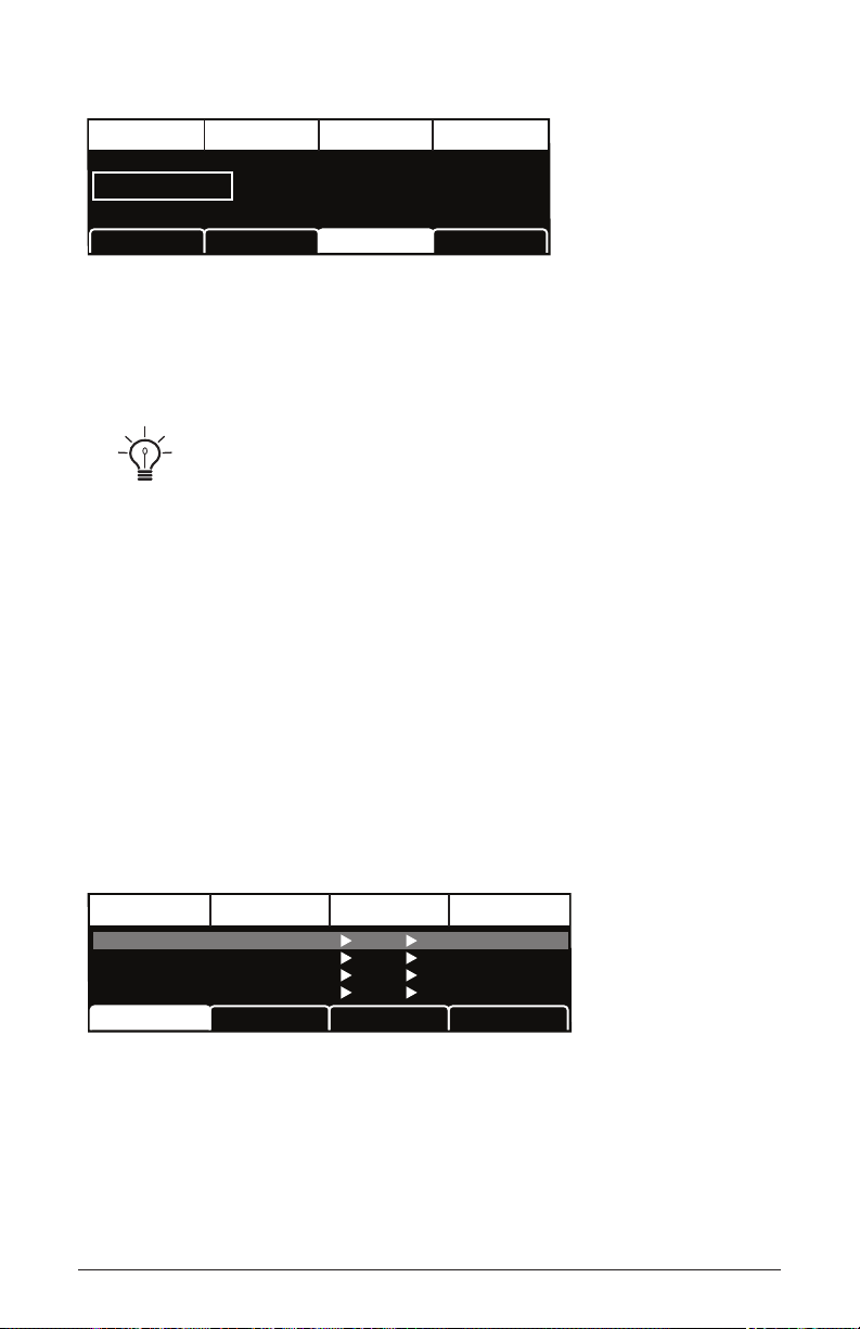
TAB 3 - LFO Dest
DestinationEdit Mod 1 Source Amount
Sort SourceSlot Sort
Mod 1
Mod 2
Mod 3
Mod4
Slider 1
Slider 2
Aftertouch
Mod Wheel
60
35
25
80
Cuto
Osc1 Shape
Drive
LFO1 Amt
Sort Dest
Destination
Osc All Freq
DESTINATION
LFO ControlLFO Shape
LFO Dest
Destination: Routes the selected LFO to one of the many modulatable
destinations within the synthesizer. You can also use the modulation
matrix to route an LFO to additional destinations.
There is a shortcut for routing an LFO to a front-panel destination (provided
that the destination is a valid destination). Simply hold down the selector button of the
desired LFO or the LFO’s destination button, then move the knob or control you want
to use as a destination (the lter cutoff, for example). Set the amount using the LFO
amount knobs. Be aware that not all front-panel controls can be used as a modulation
destinations.
Modulation
Although the overall sonic character of the Pro 3 is determined by its
oscillators and lters, much of its power to make truly unique sounds
comes from creative use of modulation. Modulation is the process of
routing one parameter (used as a control voltage) to another parameter in
order to change the way the targeted parameter behaves.
The Modulation Matrix
46
Modulation
Sequential
Page 59
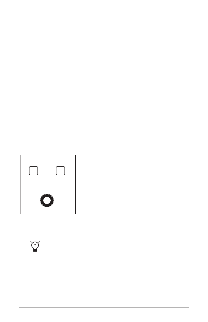
The concept is simple:
AMOUNT
SOURCE DESTINATION
MODULATION
1. Choose a source.
2. Choose a destination.
3. Set an amount. The amount can either be positive or negative.
You already understand and apply the concept of modulation whenever
you use the lter envelope to control the lter’s cutoff frequency. In this
case, the modulation source is the lter envelope (or more precisely, any
of its controls, such as attack, decay, sustain, or release). The modulation
destination is the lter’s cutoff frequency. The modulation amount is set
with the Filter Envelope’s amount knob.
There are 46 different modulation sources and 171 different destinations
to choose from. (See page 119 for a complete list.) There are also 32
freely assignable modulation paths (mod slots 1-32) as well as 5 additional dedicated mod sources including LFO 1-3, and Auxiliary Envelope
1 and 2. This gives you a large number of sound-shaping options.
The Modulation section
There are shortcuts for routing modulation to various front panel sources/destinations. Simply hold down the source button and move the control you want to use
as a source (the Mod wheel, for example). Then hold down the destination button and
move the control that you want to use as a destination (lter cutoff, for example). Set
the amount with the amount knob while referring to the display. Be aware that not all
front-panel controls can be used as a modulation sources/destinations.
Pro 3 User’s Guide
Modulation
47
Page 60

Modulation Parameters (Front Panel)
Source: Selects a modulation source. The are 34 different modulation
sources. See page 119 for a complete list.
Destination: Selects a modulation destination. The are 88 different
modulation destinations. See page 120 for a complete list.
Amount Sets the modulation amount. Modulation can be either positive
or negative.
Additional Mod Matrix Parameters (Display Menu)
Additional mod matrix parameters are accessible through the menus in
the main display. To see these, press the source or destination button on
the front panel.
Sort Slot: Arranges the modulation list in order of slot number (1-32)
Sort Source: Arranges the modulation list by modulation source. LFOs
are grouped together, envelopes are grouped together, and so on.
Sort Dest: Arranges the modulation list by modulation destination.
Oscillator parameters are grouped together, effects parameters are
grouped together, and so on.
Modulation Examples
Here are several modulation scenarios that illustrate how to use the modulation matrix. The examples provide step-by-step instructions for clarity. Some
of these setups are built into the basic program, which you can recall from
the global menu.
To use the Mod wheel to add vibrato:
1. In the lfo section, set LFO 1 to triangle and set frequency to 75. Set
destination to osc all freq. Set amount to 0. (You will control the
amount with the Mod wheel.)
2. In the modulation section, press the source button. Use soft knob 1 to
scroll to Mod Slot 1 if it’s not already displayed.
Modulation
48
Sequential
Page 61

3. Use soft knob 2 to scroll through the various mod sources and choose
mod wheel (As a shortcut you can hold down the source button and
move the Mod wheel.)
4. Use soft knob 3 to set the amount to 30.
5. Use soft knob 4 to scroll through the various mod destinations and
choose lfo1 amt.
6. Hold down a note on the keyboard and turn the Mod wheel. You should
hear vibrato.
Use pressure as the modulation source instead of the Mod wheel in the previ-
ous example to add vibrato with key pressure/aftertouch.
To use the Touch slider to control the lter cutoff:
1. In the modulation section, press the source button. Use soft knob 1 to
scroll to Mod Slot 1 if it’s not already displayed.
2. Use soft knob 2 to scroll through the various mod sources and choose
slider.
3. Use soft knob 4 to scroll through the various mod destinations and
choose cutoff.
4. Hold down a note on the keyboard (or press the hold button and play a
note on the keyboard) and move a nger up and down the Touch slider.
5. Use soft knob 3 to set the amount to your preference. Higher amount
settings cause the lter to open wider the farther up you move your
nger along the Touch slider. A negative amount setting will close the
lter farther up you move your nger along the Touch slider.
Use pressure as the modulation source instead of the Touch slider in the
previous example to open the lter (positive amount) or close the lter (negative
amount) with pressure.
Pro 3 User’s Guide
Modulation
49
Page 62

Other modulation ideas:
• To create the classic “attack pitch blip” effect in many synth brass sounds,
choose a good three-oscillator synth brass sound then route Aux Envelope
1 to osc 2 coarse freq and set Aux Envelope 1 to Attack: 0, Decay: 30,
Sustain: 0, and Release: 0 with an amount of 18.
• Route an LFO to pan to create an auto-panning effect. Panning width is
controlled by the modulation amount. Panning speed is controlled by
the LFO frequency. Add a second mod path to control the LFO speed
with the Mod wheel for a controllable rotating speaker spin-up/spindown effect. Add the rotating speaker effect as Effect 1 and set up a
third mod path to control fx1 mix with the Mod wheel for even better
results.
• Route velocity to distortion to overdrive a synth lead sound the harder
you play.
• Tune Oscillator 3 to a perfect 5th (7 semitones) and set its mixer level
to 0. Then create a mod path to control Osc 3 level with the Mod
wheel or Touch slider so you can add it to the mix in live performance.
Finally, add distortion to the sound and you can create a convincing
“guitar-with-controllable-feedback” effect.
Effects
You can add two digital effects to any Pro 3 program. Not all sounds need
effects to make them interesting, but adding a touch of delay or reverb
can add a sense depth, just as adding chorus, anging, or phasing can add
movement. Effects settings are saved individually with each program.
If you enable sync for time-based effects such as the delays, their repeat
rate is synchronized to the Arpeggiator, Sequencer, or MIDI clock for repeats
that occur on the beat.
Effects
50
Sequential
Page 63
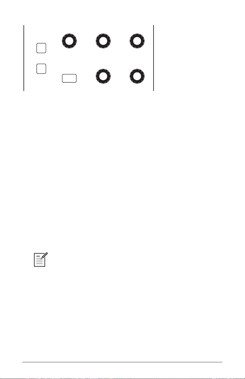
EFFECTS
EFFECT 1
EFFECT 2
ON/OFF
The Effects section
SHOW EFFECTS PARAM 1 PARAM 2
PARAM 3MIXEFFECT TYPE
Effects:
• Stereo Delay - classic digital delay
• BBD Delay - vintage bucket-brigade emulation
• Chorus - vintage chorus
• Flanger - vintage through-zero anger
• Phaser - vintage 6-stage phaser
• HP Filter - high-pass lter.
• Ring Mod - ring modulation
• Rotating Speaker - vintage rotating speaker emulation
• Super Plate Reverb - plate reverb with variable time, tone, and
early reections. Available on Effect 2 only.
For best results, run the anger and high-pass lter 100% wet (set the mix
parameter to 127).
Pro 3 User’s Guide
Effects
51
Page 64

To use Effects:
1. Press the effect 1 button to turn on effect 1.
1. Press Soft Button 2 (fx1 params) in the display to select effect 1 for
editing.
2. Turn the effect type knob to choose an effect.
3. Turn the mix knob to blend in a good amount of the processed signal.
You’ll want to be able to clearly hear the effect when you tweak its
settings. You can dial it down afterward.
4. Use the param 1, param 2, and param 3 knobs to adjust the effect’s
parameters to your taste. See “Effects Parameters” on page 52 for
details on the adjustable parameters on each effect type.
5. Finally, adjust the mix knob again to optimize the amount of the effect.
Full left is completely dry. Full right is completely wet (a 100%
processed signal).
6. To sync a delay to the Arpeggiator or Sequencer, enable its sync parameter and adjust the time parameter (Parameter 1) as needed.
Effects Parameters (Front Panel)
Effect 1: Turns effect 1 on or off.
Effect 2: Turns effect 2 on or off.
Effect Type: stereo delay, bbd delay, chorus, anger, phaser, HP lter,
ring mod, rotating speaker, super plate—Selects the effect type.
Show Effects: Shows the Effects menu in the display for editing. Press-
ing this button more than once toggles between the two effects in the
display.
Mix: 0...127—Sets the balance between the processed (wet) signal
and unprocessed (dry) signal. Full left is completely dry. Full right is
completely wet.
Effects
52
Sequential
Page 65

Sync (in the main display): On, Off—When a delay effect is chosen, this
enables syncing of the timed delay repeats (feedback) to the Arpeggiator,
Sequencer, or MIDI clock. When sync is on, delay time has the following
values:
Value Delay Time
Whole (1) 4 beats
Half dot (2D) 3 beats
Half (2) 2 beats
Quarter dot (4D) 1 1/2 beats
Quarter (4) 1 beat
Quarter triplet (4T) 1 1/3 beats
8th dot (8D) 3/4 of 1 beat
8th (8) 1/2 of 1 beat
8th triplet (8T) 1/3 of 1 beat
16th dot (16D) 3/8 of 1 beat
16th (16) 1/4 of 1 beat
Maximum delay time is approximately 1 second. The combination of longer
synced delay times with slower tempos can result in delay times that would be greater
than 1 second. When that happens, the delay time is divided by 2 until it no longer
exceeds the 1 second limit. For example, if the BPM is set to 60 and Delay Time
(Parameter 1) is set to Half, the expected delay time would be 2 seconds. The actual
delay time will be 1 second (i.e. 2 seconds divided by 2).
Parameter 1: Variable, depending on the effect—This knob adjusts
parameter 1 for the chosen effect. Each effect has three adjustable
parameters, which differ depending on the effect.
Parameter 2: Variable, depending on the effect—This knob adjusts
parameter 2 for the chosen effect. Each effect has three adjustable
parameters, which differ depending on the effect.
Parameter 3: Variable, depending on the effect—This knob adjusts
parameter 3 for the chosen effect. Each effect has three adjustable
parameters, which differ depending on the effect.
Pro 3 User’s Guide
Effects
53
Page 66
Effect Type Param 1 Param 2 Param 3
stereo delay delay time feedback amount low-pass lter cutoff
BBD delay delay time feedback amount low-pass lter cutoff
chorus depth rate low-pass lter cutoff
anger depth rate feedback
phaser depth rate feedback
high-pass lter frequency resonance
ring mod frequency track shape
rotating speaker drive speed mic distance
super plate reverb time tone pre-delay
To recreate a classic time-shifting effect on the stereo or BBD delay, try adjusting the delay time parameter in real time. You can also route an LFO or envelope to
the delay’s Time parameter using the modulation matrix.
Arpeggiator
The Arpeggiator allows you to hold a chord and the synthesizer will play
a pattern based on the individual notes held. You can adjust the playback
mode (up, down, up+down, random, assign.), the octave range (1, 2,
or 3), the number of repeats per note, and the tempo. The Arpeggiator
usually works best on sounds with a fast attack.
While you hold down a chord, pressing any additional notes will add
those notes to the arpeggio. You can change chords and notes and the
arpeggio will continue to play as long as at least one note is always held.
You can also use the hold feature with the Arpeggiator. When you enable
hold, you can release the notes on the keyboard and the arpeggio will
continue to play — with any additional notes that you play added to the
arpeggio.
To prevent the Arpeggiator from adding new notes to an arpeggio when keys
are continuously held (and instead start a new arpeggio each time you change notes),
turn arp relatch on in the Arpeggiator. To do this, press the Arpeggiator’s on/off button
and turn Soft Knob 3 to turn arp relatch on in the display.
Arpeggiator
54
Sequential
Page 67
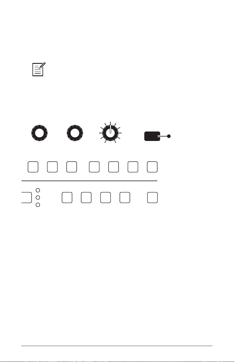
Set the tempo of the Arpeggiator with the tap tempo or bpm and divide
controls. To use tap tempo, tap this button 4 times to set the tempo. You
can also sync the Arpeggiator to external MIDI clock, or even an external audio signal.
The Arpeggiator can run concurrently with the Sequencer for arpeggiated
patterns with sequenced parameter automation. To do this, turn on the Arpeggiator
and set the Sequencer mode to trigger. The Sequencer will step with each Arpeggiator step. You can even record parameter changes during Arpeggiator playback by
holding down the Sequencer’s record button and turning knobs to make parameter
changes in real time. The parameter changes will be recorded and included in the
sequence.
Press to enable
the Arpeggiator
BPM DIVIDE SWING ARPEGGIATOR
10 11 12 13 14 15 16
assign 6 assign 7 assign 8 CV out 1 CV out 2 CV out 3 CV out 4
Normal
Gated
Trigger
The Arpeggiator
fwd
rev fwd/rev random
RESETDIRECTION
To use the Arpeggiator:
1. Press the arpeggiator on/off button to turn it on.
2. Hold down one or more notes on the keyboard. The Arpeggiator plays
them according to the settings you’ve chosen.
3. To latch arpeggiation on (so that you don’t have to continuously hold
down notes) press the hold button.
4. In the display menu, adjust settings such as mode, octave range,
repeats, and bpm.
5. To synchronize a delay effect to the Arpeggiator, enable Effect 1 or Effect
2, choose a delay, then turn on sync in the delay’s parameter page in the
display. Adjust the delay’s time parameter as desired.
Pro 3 User’s Guide
Arpeggiator
55
Page 68

Arpeggiator “Momentary Sustain” Mode
The Pro 3 allows you to use the sustain pedal to turn the Arpeggiator’s
Hold function on and off and perform other Arpeggiator-related functions. To access this feature, use the footswitch function setting in the
global menu.
ere are three modes to choose from:
• - With the Arpeggiator running in this mode, pressing and
holding the Sustain pedal sustains the notes, as the Sustain pedal
normally would.
• - With the Arpeggiator running in this mode, pressing the
Sustain pedal once causes the Arpeggiator to hold the sequence (even
when you release the notes on the keyboard). Pressing it again stops the
Arpeggiator.
• - With the Arpeggiator running in this mode, pressing
and holding the Sustain pedal causes the Arpeggiator to sustain (even
when you release the notes on the keyboard) for as long as you hold
down the pedal. Releasing the Sustain pedal stops the Arpeggiator.
To select the Arpeggiator’s sustain pedal mode:
1. Press the button then use So Knob 1 to scroll to
.
2. Use So Knob 3 to select , , or ,
depending on your preference. Press the button again to exit
the Global menu.
Arpeggiator
56
Sequential
Page 69

MIDI Note Output from the Arpeggiator
e Arpeggiator outputs MIDI note messages. Any notes that you hold
on the keyboard will be arpeggiated according to the current settings of
the Arpeggiator and output over MIDI as MIDI notes. You can use this
feature to drive other MIDI-equipped devices such as synthesizers and
drum machines. To access this feature, use the setting in
the menu.
To enable MIDI Note output from the Arpeggiator:
1. Press the button, then turn So Knob 1 to select
.
2. Turn So Knob 3 to select .
To control an external MIDI device:
1. Connect the MIDI or USB output of the Pro 3 to the MIDI or USB
input of the external device, depending on which type of connection
the external device requires.
2. On the Pro 3, press the global button, then use Soft Knob 1 to select
midi out select.
3. Use the So Knob 3 knob to select , or , or +, depending on how your Pro 3 and external device are connected.
4. Press the button again to exit the Global menu.
5. On the external device, set the the MIDI Channel and MIDI Receive
port to match the Pro 3.
6. Hold down a chord on the Pro 3 or start Sequencer playback. e external device should be triggered by the arpeggiated or sequenced notes.
Pro 3 User’s Guide
Arpeggiator
57
Page 70

Arpeggiator Parameters (Display Menus)
Arp Mode Arp RelatchOctave Range Repeats
REPEATS
ARP RELATCH
Seq ModesBPM ArpSeq Param
OCTAVE RANGEARP MODE
Up+Down 1 Oct 0
Arpeggiator parameters are accessible through the menus in the main
display. To see these menus, adjust any of the controls in arpeggiator
section of the front panel.
Front Panel Arpeggiator On/Off Button—This button turns the Arpeg-
giator on and off.
The Arpeggiator menu
Arp Mode: Sets the order in which notes play when the Arpeggiator is on. See
the table.
Arp Mode Behavior
Up Plays from lowest to highest note
Down Plays from highest to lowest note
Up + Down Plays from lowest to highest and back to lowest
Random Plays notes in random order
Assign Plays notes in the order the keys were pressed
Octave Range: 1, 2, 3 —Set to 1, only the held notes are arpeggiated.
Set to 2, the held notes and the notes one octave above them arpeggiate.
Set to 3, the held notes and the notes one and two octaves above them
arpeggiate.
Relatch: Off, On—Works in conjunction with hold. When hold and the
Arpeggiator are on, and arp relatch is off, played notes are held on and
arpeggiated, with additional played notes added to the held notes and the
arpeggio. When arp relatch is on, played notes are held on and arpeggiated, but additional played notes will restart the arpeggio with the new
notes.
58
Arpeggiator
Sequential
Page 71

Repeats: 1, 2, 3 —Set to 1, each note in the arpeggio plays once. Set to
2, each note in the arpeggio plays twice. Set to 3, each note in the arpeggio plays three times.
Clock Parameters
BPM: 30…250—Sets the tempo for the Arpeggiator in BPM (beats per
minute). The tap tempo LED ashes at the BPM rate. When sync is enabled
on the low-frequency oscillator, or enabled in the Effects section, the BPM
rate affects the LFO frequency and/or delay effect. When syncing to an external MIDI clock source, the BPM setting has no effect.
Divide—Selects a basic note value relative to the BPM. See the table below:
Name Tempo Timing Division
Half BPM/2 Half note
Quarter BPM Quarter note
8th BPM x 2 Eighth note
8 Trip BPM x 3 Eighth note triplets
16th BPM x 4 Sixteenth note
16 Trip BPM x 6 Sixteenth note triplets
32nd BPM x 8 Thirty-second note
32 Trip BPM x 12 Thirty-second note triplets
64th BPM x 16 Sixty-fourth note
Tap Tempo—Pressing the tap tempo button 4 times sets the tempo. The
LED ashes at the BPM rate you set.
Pro 3 User’s Guide
Arpeggiator
59
Page 72

Sequencer
The original Sequencers in modular synthesizers were used as a modulation source. They produced a series of control voltage events at timed
intervals that could be used to change the value of a synth parameter
in discrete steps. Sequences could be routed to oscillator frequency to
produce a series of pitched notes, to lter frequency to produce stepped
ltering effects, and so on.
The Pro 3 Sequencer is like its analog precursors but more powerful. The
Pro 3 Sequencer has 16 tracks and 4 linkable 16-step phrases (A,B,C,D)
for creating repeating patterns of notes, or 3-note chords in paraphonic
mode.
You can create sequences of variable length and add rests, ties, per-step
ratcheting, and adjust duration, and velocity. Each Sequencer track can
be routed to a different modulation destination using the mod matrix, and
each step in a sequence can be set to a different value to modulate that
destination.
All factory programs have a sequence associated with them. Recall a
program and press the Sequencer’s play button to hear its associated
sequence.
Normal, Gated, and Trigger Modes
The Sequencer has three modes of operation that control how sequence
playback is started: Normal, Gated, and Trigger.
Normal — In normal mode, sequence playback starts when you press
the play button.
Gated — In gated mode, sequence playback starts and continues as long
as you hold down a key on the keyboard.
Trigger — In trigger mode, sequence playback is initiated by a specic
type of trigger:
Sequencer
60
Sequential
Page 73

• Keyboard trigger. Repeatedly pressing a key on keyboard advances the
BPM DIVIDE SWINGTAP TEMPO ARPEGGIATORVALUE
1 2 3 4 5 6 7 8 9 10 11 12 13 14 15 16
TRACKS
SLEWSEQ LOCKCUE PGM
TRACK SEL
notes/vel duration ratchet cutoff assign 1 assign 2 assign 3 assign 4 assign 5 assign 6 assign 7 assign 8 CV out 1 CV out 2 CV out 3 CV out 4
A B C D
SEQUENCE RECORD PLAY MODE RESETDIRECTION
fwd
Normal
Gated
Trigger
rev fwd/rev random
Play Source RestartSync to Trk 1 Para Seq
PARA SEQ
RESTART
Seq ModesBPM ArpSeq Param
SYNC TO TRK1PLAY SOURCE
Keyboard On O
Notes
Velocity
Step: A1 Note C5 Vel: 80Track: 1
C5C5C5C5C5C5C5C5C5C5C5C5C5C5C5C5C
5
Duration Ratchet Seq AVelocity
sequence one step each time you press a key.
• The Arpeggiator. Selecting trigger mode, then turning on the Arpeggiator and holding down a chord on the keyboard runs the sequence
while notes are held. In this case, sequenced Note tracks are ignored
and only parameter automation tracks are played. This is useful for
adding sequenced lter sweeps or other modulation to an arpeggio.
• External input trigger. External input triggers include an external audio
input signal, MIDI, or a control voltage input.
The Sequencer
The Sequencer Parameters menu (press the arpeggiator button to display)
The sequence editor (press the track sel button to display)
Pro 3 User’s Guide
Sequencer
61
Page 74

Programming the Sequencer
By default, Track 1 of the Sequencer controls oscillator frequency, meaning that it’s hard-wired for recording notes. Beyond that, any Sequencer
track can be routed to any modulation destination. A typical scenario
might have other tracks routed to lter cutoff, lter resonance, noise
level for drum-like accents, and so on.
To program a monophonic note sequence:
1. Select a program with a relatively sharp attack and short release.
2. Press the record button. Phrase A is selected by default.
3. Play a sequence of notes on the keyboard. The numbered step LEDs
indicate where you are in the sequence. A white LED indicates the current
step. A red LED indicates a note has been recorded on that step.
4. If you make a mistake, toggle the record button off, then on again, and
replay the notes correctly.
5. If you want to record fewer than 16 steps, play only the notes you want.
If you play more than 16 notes/steps, the Sequencer will ignore the
additional notes.
6. When you’ve nished, press the play button to hear your sequence. A
white LED indicates the current step. A red LED indicates a note has been
recorded on that step.
7. Use the bpm, divide, or tap tempo controls to adjust Sequencer playback
speed.
8. To change playback direction of the sequence, press one of the direc-
tion buttons (rev, fwd/rev, random).
9. To stop playback, press the play button again.
10. To save the sequence, save the program by pressing the write button
twice.
A quick way to edit a step when playback is stopped is to press and hold the step
LED for the desired step. You can then play a note and the Sequencer will update the
sequence to use that note and the velocity at which you played it. You can also edit any
other parameter for that step while you’re at that step location.
Sequencer
62
Sequential
Page 75

To transpose a sequence up or down during playback:
1. Press the play button to hear the sequence.
2. Press a note on the keyboard above or below middle C. The sequence is
transposed to that key. (Middle C plays the sequence as recorded.) For
greater range, use the Transpose Up or Transpose Down buttons.
3. During playback, if you want to restart a sequence from step 1, press
the reset button.
To record over an existing note sequence:
1. Press the record button.
2. Play different notes on the keyboard. The numbered step LEDs indicate
which step you’re on.
3. When you’re done, press play to listen to the new sequence.
4. To resave the sequence, save the program by pressing the write button
twice.
Recording Phrases/Sequences A,B,C, or D.
The Pro 3 can record up to four independent phrases/sequences per
program. You can select among these by pressing the A,B,C,or D
sequence buttons on the front panel. During real-time playback you can
switch between these on the y. (You can also chain them together for
sequences longer than 16 steps. See “Creating An Extended Sequence”
on page 66 for more details.)
To record Sequence B,C, or D:
1. Press sequence button B,C, or D.
2. Press the record button and play a sequence of notes on the keyboard.
3. When you’ve nished, press the play button to hear your sequence.
As noted above, you can switch between sequences A,B,C, and D on the
y during playback by simply pressing the button of the sequence you
want to play. You can also chain them together for sequences longer than
16 steps. See “Creating An Extended Sequence” on page 66 for more
details.
Pro 3 User’s Guide
Sequencer
63
Page 76

Sequencing Parameter Changes in Real-Time
The Sequencer makes it easy to record parameter changes in real-time
as part of any of the four phrases/sequences, A,B,C, and D. To do this,
start playback, then hold down the Sequencer’s record button and adjust
front-panel controls such as lter cutoff, noise level, envelope settings,
or other parameters.
As the sequence plays, the Sequencer records the changes to the parameter and incorporates them into the sequence. Each parameter you adjust
is assigned to one of the available Sequencer tracks, 4-16. (Tracks 1-3
are reserved for note-related functions, but tracks 4-16 can be freely
assigned.)
Be aware of where and when the sequence loops back around to its
beginning since the Sequencer continues to record (and possibly overwrite) any parameter changes you make as it repeats.
To sequence parameter changes in real-time:
1. Start playback of an existing sequence by pressing the play button.
2. As the sequence plays, hold down the record button and adjust a
parameter (such as lter cutoff) in real-time. Recording loops around
with the sequence, continuously updating the changes you make.
3. As long as you continue to hold down the record button during playback you can continue to adjust that parameter or additional parameters. Each parameter is assigned to one of the available tracks, 4-16.
Sequencer
64
Sequential
Page 77

Copying a Sequence from One Track to Another
Sometimes it’s useful to copy a sequence from one track to another,
particularly when tracks are used for parameter modulation.
To copy one track to another:
1. Press the sequence button to select the sequence you want ( A, B,C, or D).
2. Press and hold the track sel button and press Soft Button 2 (copy
track).
3. Continue to hold down the track sel button and press the step LED with
the same number as the track you want to copy (step 1 = track 1, etc.).
4. Continue to hold down the track sel button, then press the step LED
with the same number as the track you want to paste the copied track onto.
Copying and Pasting an Entire Sequence
You can also copy and paste an entire sequence between sequences
A,B,C, and D. This duplicates all data on all tracks.
To copy and paste an entire sequence:
1. Press and hold the track sel button and press Soft Button 2 (copy
track).
2. Continue to hold down the track sel button and press the A, B, C, or D
sequence button, depending on which one you want to copy.
3. Continue to hold down the track sel button, then press the A, B, C, or
D sequence button, depending on which you want to paste the copied track
onto.
The Cue Program and Seq Lock features provide a simple way to copy a
sequence from one program to another. See “Cue Program” on page 79 for more
details.
Pro 3 User’s Guide
Sequencer
65
Page 78
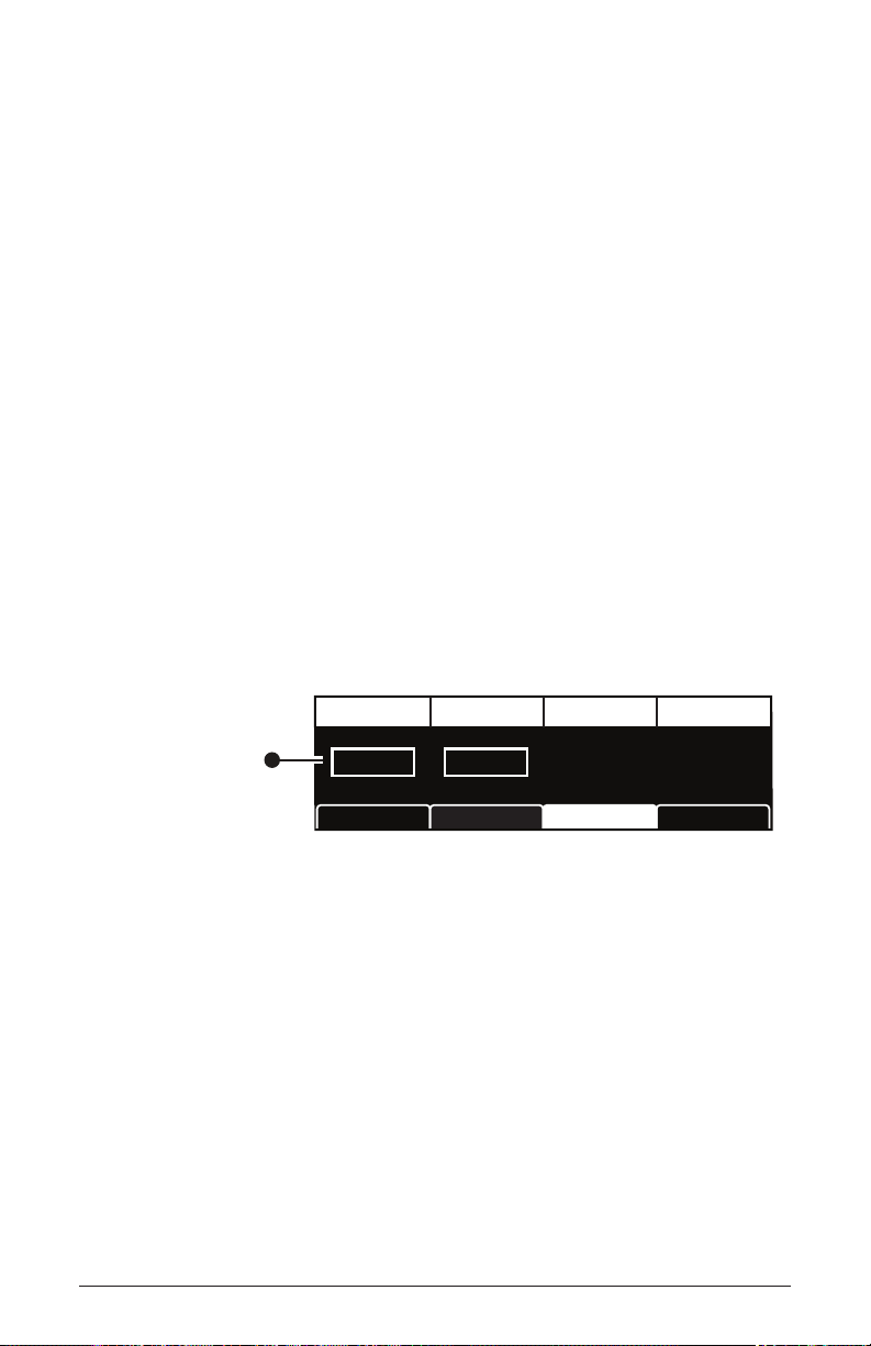
Muting a Sequence Track
Sometimes it’s useful to mute a track to ignore the sequence data
recorded on it.
To mute a Sequencer track:
1. Press the sequence button to select the sequence you want ( A, B,C, or D).
2. Press and hold the track sel button and press the step LED with the
same number as the track you want to mute (step 1 = track 1, etc.).
3. Press Soft Button 4 (mute) to set it to on. The track is muted.
4. To toggle off muting, repeat steps 2 and 3.
Creating An Extended Sequence
If want to create a sequence that’s longer than 16 notes/steps, you can do
so by putting the Sequencer in extended mode. This chains the individual
phrases/sequences A, B, C, D together. Since each of the four individual
phrases/sequences has a maximum of 16 steps, you can create a sequence
of up to 64 steps in total.
Seq Mode RestartSeq Length Para Seq
Set this parameter to
“Extended” to create
a sequence longer
than 16 steps
Extended 32 Steps
SEQ LENGTHSEQ MODE
Seq ModesBPM ArpSeq Param
Enabling extended sequence mode
Sequencer
66
Sequential
Page 79
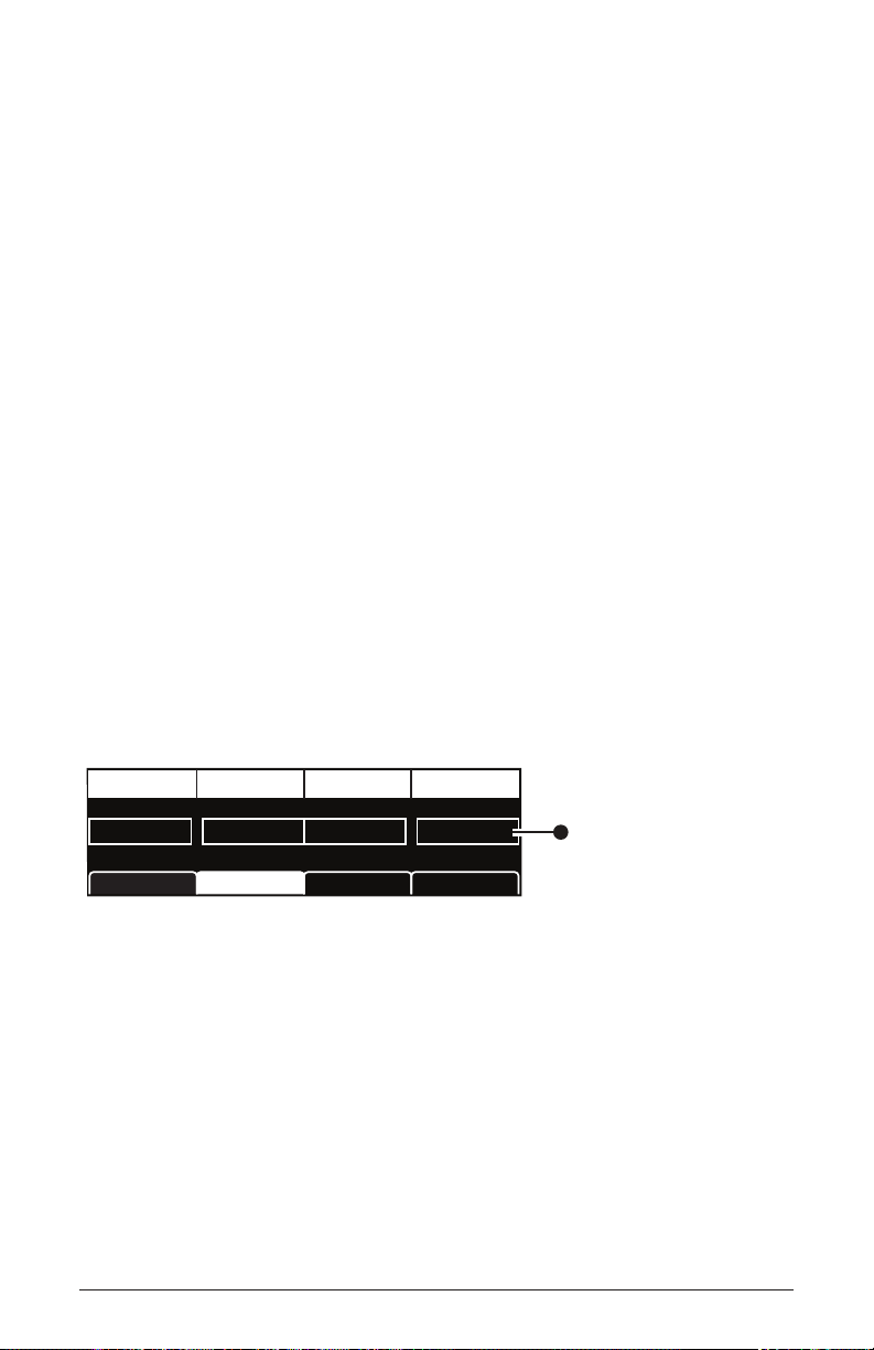
To program an extended monophonic note sequence:
Press the Paraphonic button
1. Show the Sequencer mode menu by pressing the arpeggiator button. If
necessary, press the button again to turn off the Arpeggiator
2. Press Soft Button 3 (seq modes) to select the sequencer mode menu.
3. Turn Soft Knob 1 and choose extended.
4. Turn Soft Knob 2 and choose the length of the sequence. The maximum length is 64 steps.
5. Press the record button and play the desired notes on the keyboard.
The numbered step LEDs indicate your current step location. When
you cross over into the next 16-step sequence (A,B,C,D) the appropriate LED will light up.
6. When you’re done, press play to listen to the sequence.
7. To save the sequence, save the program by pressing the write button
twice.
Paraphonic Sequencing
The Pro 3 can play and sequence 3-note chords when operating in paraphonic mode. In this mode, track 1 is routed to Oscillator 1, track 2 to
Oscillator 2, and track 3 to Oscillator 3.
Play Source Sync to Trk1 Restart Para Seq
SYNC TO TRACK 1PLAY SOURCE
BPM
Enabling paraphonic mode
Seq Params Seq Modes Arp
On OnKeyboard On
RESTART PARA SEQ
Pro 3 User’s Guide
on the front panel to enable
this parameter.
Then use soft knob 4
to select On.
Sequencer
67
Page 80

To record a paraphonic sequence:
1. Set all three oscillators to the same level in the mixer. You will probably want to set them to the same octave as well.
2. Press the paraphonic button to enable paraphonic mode. The Sequencer
menu appears in the display.
3. Press Soft Button 2 to select the seq params menu.
4. Turn Soft Knob 4 (para seq) and choose on. Paraphonic sequencing is
now enabled.
5. Press the record button and play a series of notes and chords on the
keyboard. You can play up to 3-note chords. The numbered step LEDs
indicate your current step location.
6. When you’re done inputting notes, press play. Your sequence plays
back. To stop playback, press play again.
7. To save the sequence, save the program by pressing the write button
twice.
Adding Rests, Ties, and Velocity
When recording note sequences using the keyboard, the Sequencer
assigns each note that you play (along with its velocity) to successive
steps in the sequence. However, you may want to add rests, ties, and
additional velocity changes for greater rhythmic variation.
Adding Rests
Rests turn off notes. You can add rests as you record a sequence in real
time, or you can add them after you’ve nished recording.
To add rests in real time as you record:
1. Press the record button and play a series of notes.
2. When you reach a step where you want to add a rest, press that step
LED/button. The step becomes a rest.
3. If you want to add several rests in a row, press the step LED/button
where you want the rest to end.
4. Continue playing notes as desired to complete the sequence.
Sequencer
68
Sequential
Page 81

5. When you’re done, press play. Your sequence plays back. To stop play-
BPM DIVIDE SWING
TAP TEMPO ARPEGGIATORVALUE
1 2 3 4 5 6 7 8 9 10 11 12 13 14 15 16
TRACKS
SLEWSEQ LOCKCUE PGM
notes/vel duration ratchet cutoff assign 1 assign 2 assign 3 assign 4 assign 5 assign 6 assign 7 assign 8 CV out 1 CV out 2 CV out 3 CV out 4
An unlit LED
indicates a rest
steps 2-3
back, press play again.
6. To resave the sequence, save the program by pressing the write button
twice.
A quick way to add a rest to an already-recorded sequence is to toggle off the
front-panel LED/button for that step. The step/button can be toggled on again if you want.
Unlit LEDs indicate rests (or steps with no notes recorded)
To add rests to an existing sequence using the sequence editor:
1. To show the track in the display, hold down the track sel button and
press the step LED with the same number as the track you want to edit
(step 1 = track 1, and so on).
Pro 3 User’s Guide
2. Release the track sel button. The track appears in the display.
3. On the front panel, toggle off the LEDs for the steps that you want to
rest. (The step can be toggled on again if you want.) The rest appears as
an asterisk (*) in the display.
4. Repeat for any additional steps/rests.
5. To listen to the sequence, press play.
have rests
Step: A1 Note: C5 Vel: 66Track 1
Notes
Velocity
Velocity Duration Ratchet Seq: A
C
3
D3F3C3G3F3A3C3G4F4S4C4C5C
* *
* *
3
Sequencer
69
Page 82

LEDs are off on steps that are rests.
Adding Ties
Ties allow you to increase the duration of a note in a sequence (i.e. the
number of steps that it’s held). You can add ties as you record a sequence
in real time, or you can add them after you’ve nished recording
To add ties in real time as you record:
1. Press the record button and play a series of notes.
2. When you reach a step where you want to add a tie, play the note on
the keyboard, then press and hold that step LED/button (the LED will
be red).
3. With that step LED/button still held down, press the step LED/button
where you want the tie to end. That series of steps is now tied and the
note sustain for that duration.
4. Release the buttons.
5. Continue playing notes as desired to complete the sequence.
6. When you’re done, press play. Your sequence plays back. To stop playback, press play again.
The note is tied
on steps 1-3
Step: A1 Note: C5 Vel: 66Track 1
Notes
Velocity
Velocity Duration Ratchet Seq: A
notes sustain.
Sequencer
70
C
3
LEDs are dimmed on steps that are tied.
Envelope setting and the Sequencer’s duration parameter may affect how tied
D3F3C3G3F3A3C3G4F4S4C4C5C
+ +
3
Sequential
Page 83

To add ties to an existing sequence:
1. To show the track in the display, hold down the track sel button and
press the step LED with the same number as the track you want to edit
(step 1 = track 1, and so on).
2. Release the track sel button. The track appears in the display.
3. On the front panel, press and continue to hold the LED button for the
step where the tie will start.
4. Press the LED button for the step where the tie will end.
5. Release the buttons.
6. To create additional ties, repeat steps 3-5.
Editing Velocity
When you use the keyboard to record note sequences in real time,
the Sequencer records note velocity along with the note values. The
sequence editor allows you to edit these values.
To edit velocity on an existing sequence:
1. To show the notes track in the display, hold down the track sel button
and press step LED 1 (notes/vel). Note that if the sequence is para-
phonic, tracks 2 and 3 are also note tracks.
2. Release the track sel button. The notes track appears in the display.
3. Press Soft Button 1 (velocity) to display the velocity parameter for the
track.
4. Turn Soft Knob 1 (step) to scroll to the desired step.
5. Turn Soft Knob 4 (vel) to edit the velocity value of the selected step.
6. Repeat steps 4 and 5 as desired.
Velocity is only available for editing on note tracks or tracks that have (MIDI)
Out 1 or Out 2 as their destination.
If you have a Sequencer track assigned to a MIDI channel output and it is only
sending MIDI note-off messages, check the value of the Velocity parameter for each step.
A velocity greater than zero must be set for a MIDI note-on message to be sent. If the
velocity for a given step is set to zero, only a MIDI note-off message will be sent for that step.
Pro 3 User’s Guide
Sequencer
71
Page 84

Editing Duration
You can use the Sequencer editor to edit the gate duration of notes after
you’ve recorded them. This is useful for creating staccato or legato effects.
To edit duration on an existing sequence:
1. To show the notes track in the display, hold down the track sel button
and press step LED 1 (notes/vel). Note that if the sequence is para-
phonic, tracks 2 and 3 are also note tracks.
2. Release the track sel button. The track appears in the display.
3. Press Soft Button 2 (duration) to display the duration parameter for the
track.
4. Turn Soft Knob 1 (step) to scroll to the desired step.
5. Turn Soft Knob 4 (dur) to edit the duration value of the selected step.
Lower values create staccato effects. Higher values create legato
effects.
6. Repeat steps 4 and 5 as desired.
Adding Ratcheting
Ratcheting adds tuplet effects by repeating a note trigger multiple times on
the same step. You can choose from 1 to 8 repetitions per step. You may
need to adjust envelope settings and a step’s duration parameter to hear each
repetition, depending on the sequence.
To add ratcheting to an existing sequence:
1. To show the notes track in the display, hold down the track sel button
and press step LED 1 (notes/vel). Note that if the sequence is para-
phonic, tracks 2 and 3 are also note tracks.
2. Release the track sel button. The track appears in the display.
3. Press Soft Button 3 (ratchet) to display the ratchet parameter.
4. Turn Soft Knob 1 (step) to scroll to the desired step.
5. Turn Soft Knob 4 (rcht) to edit the ratchet value of the selected step.
6. Repeat steps 4 and 5 as desired.
Sequencer
72
Sequential
Page 85

Editing Other Elements of a Sequence
You can edit other aspects of a sequence as well, including note values and
per-step modulation amounts for any tracks used to modulate synth param-
eters such as lter cutoff, and so on. This is convenient for xing mistakes,
modifying a sequence, or adding and rening elements of a sequence.
To use the sequence editor:
1. Press the sequence button to select the sequence you want to edit: A,
B,C, or D.
2. To show the desired track in the sequence editor, hold down the track
sel button and press the step LED with the same number as the track you
want to edit.
3. Release the track sel button. The track appears in the display.
To edit notes:
1. Make sure track 1 (initnote) is displayed. Then use Soft Knob 1 (step)
to scroll to the step you want to edit.
2. Use Soft Knob 3 (note) to change the note (C0 - G10).
3. To re-save the sequence, save the program by pressing the write button
twice.
To edit a note’s velocity:
1. Make sure track 1 (initnote) is displayed. Then use Soft Knob 1 (step)
to scroll to the step you want to edit.
2. Press Soft Button 1 to active the velocity tab, then turn Soft Knob 4
(vel) to enter a velocity value, 1-127. Turning the knob fully counterclockwise sets the step to rest.
3. To re-save the sequence, save the program by pressing the write button
twice.
A quick way to edit a step when playback is stopped is to press and hold the step
LED for the desired step. You can then edit any parameter for that step while you’re at that
step location.
Pro 3 User’s Guide
Sequencer
73
Page 86

To edit a track used for modulation:
1. Press the sequence button to select the sequence you want to edit: A,
B,C, or D.
2. To show the desired track in the display, hold down the track sel
button and press the step LED with the same number as the track you
want to edit.
3. Use Soft Knob 1 (step) to scroll to the step you want to edit.
4. Turn Soft Knob 3 (val) to enter a value, 1-127. Most values range from
-127 to +127.
5. To save the sequence, save the program by pressing the write button
twice.
Setting or Changing the Destination of a Track
Each of the four sequences, A,B,C, and D have 16 tracks. Tracks 1-3 are
reserved for note-related functions. Tracks 4-16 can be freely assigned.
To set or change the destination of a sequence track:
1. Show the desired sequence and track in the display by pressing the
sequence button to select the sequence you want ( A, B,C, or D) then
holding down the track sel button and press the step LED with the
corresponding track number you want to edit.
2. Press and hold the track sel button and turn Soft Knob 4 to scroll
though a list of destinations. Remember that tracks 1-3 are reserved for
note-related functions. Tracks 4-16 can be freely assigned.
A quick way to set the destination of a Sequencer track is to hold down the track
select button and turn the front-panel knob for the parameter you want to route to that
track.
Sequencer
74
Sequential
Page 87

Recording Additional Sequencer Tracks for Modulation
Tracks 4-16 can be freely assigned to any modulation destination. You
can either start the Sequencer running and record the modulation values
in real time by turning parameter knobs (in which case the Sequencer
automatically assigns a track to the edited parameter) or you can input
values step by step with the Sequencer stopped.
Here’s how to sequence lter cutoff modulation step-by-step.
To modulate lter cutoff frequency using Sequencer Track 4:
1. Press and hold the track sel button then press Sequencer step LED 4.
(Alternatively, turn Soft Knob 1 (select track) to select track 4.)
2. While continuing to hold down the track select button, turn Soft Knob
4 (dest) to select cutoff.
3. Release the track select button.
4. Turn Soft Knob 1 to go to the desired step in the sequence
5. Turn Soft Knob 3 (val) to set a value.
6. Repeat steps 4 and 5 for each step in the sequence until nished.
7. To listen to the sequence, press play.
If the length of track 1 (notes) is longer or shorter than the modulation tracks in a
sequence, you can make all tracks restart to step 1 when track 1 plays step 1 by enabling
sync to track 1 in the seq params menu (pres the arpeggiator button to display this menu).
Pro 3 User’s Guide
Sequencer
75
Page 88

Using Slew
Slew creates a smooth transition between successive, discrete control
voltage levels. You can use slew to create glide effects between note
values, a smooth lter cutoff sweep, and so on, depending on the parameter being sequenced.
To add slew to a sequence track:
1. Show the desired sequence and track in the display by pressing the
sequence button to select the sequence you want ( A, B,C, or D) then
holding down the track sel button and press the step LED with the
corresponding track number you want to edit.
2. Press the slew button. A preset amount of slew is added to the track.
3. To hear the effect, press play to start the sequence.
Turning off the Sequencer’s “Notes” Track
By design, Sequencer track 1 always controls oscillator frequency,
meaning that it is effectively hard-wired for recording notes. However,
you may want to use the Sequencer to control other parameters without
having it trigger notes. By doing so, you can freely play notes on the
keyboard while the Sequencer controls other non-note parameters such
as lter cutoff, effect amount, oscillator shape mod, and so on.
To turn off Notes on the Sequencer:
1. Create a sequence with parameter automation.
1. Press and hold the front panel track sel button. Track 1 should be
displayed by default. If not, continue holding down the track sel
button and press the step 1 button/LED.
2. Continue to hold down the track select button press Soft Button 3
(notes) to set it to off.
3. Press the front panel mode button and select gated.
4. Play a series of notes on the keyboard. You’ll hear the sequenced
parameters change as you play the notes.
Sequencer
76
Sequential
Page 89

Sequencer Parameters (Front Panel)
Track Select: Pressing the button displays the sequence editor. Press-
ing and holding this button displays various commands for setting track
destination, copying a sequence, turning notes on or off, and muting a
track. Pressing and holding this button and pressing a step LED selects
the corresponding track number and displays it in the sequence editor.
Sequence: A, B,C, D—These buttons select the active sequence.
Record: On, Off—This button turns sequence recording on and off.
Play: On, Off—This button starts and stops sequence playback.
Mode: Normal, Gated, Trigger—This button selects the playback mode.
See “Normal, Gated, and Trigger Modes” on page 60 for more details.
Direction: fwd, rev, fwd/rev, random—This button sets the direction of
sequence playback.
Reset: Pressing this button switch restarts sequence playback at step 1.
Seq Lock: On, Off—Enabling seq lock switch keeps the current sequence
active while you change programs. In this way you can continue to run
the same sequence while recalling different sound programs. If you save a
program while using Seq Lock, it will save the sequence to that program and
overwrite an existing sequence on that program.
Slew: On, Off—Turning on slew creates a smooth transition between the
successive, discrete control voltage levels on each sequence step. Use
slew to create glide effects between note values, a smooth lter cutoff
sweep, and so on, depending on the parameter being sequenced. You can
enable Slew individually for each track.
Tap Tempo: 30…250—Tap this button two or more times to quickly set
the tempo for the Sequencer and Arpeggiator. The LED ashes at the
BPM rate you set. For best results, tap the button 4 times.
BPM: 30…250—Sets the tempo for the Sequencer and Arpeggiator in
BPM (beats per minute). When Sync is turned on for an LFO or Delay,
the BPM rate affects its LFO frequency or delay time. When syncing to
an external MIDI clock source, the BPM setting has no effect.
Pro 3 User’s Guide
Sequencer
77
Page 90
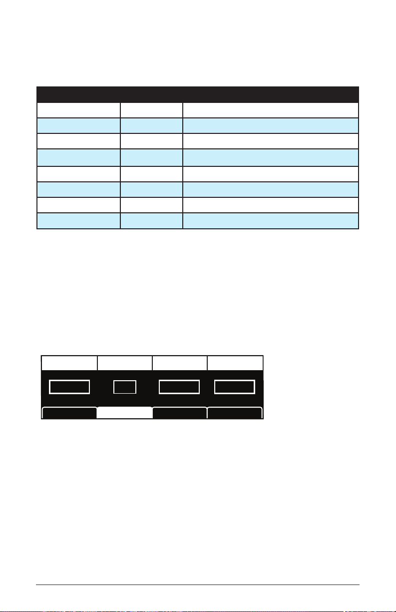
Divide: Sets the note value for each Sequencer/Arpeggiator step relative
Play Source RestartSync to Trk 1 Para Seq
PARA SEQ
RESTART
Seq ModesBPM ArpSeq Param
SYNC TO TRK1PLAY SOURCE
Keyboard On O
to the BPM. divide works with both internal and external clock sources.
The following table lists the divide values.
Display Tempo Timing Division
Half BPM/2 Half note
Quarter BPM Quarter note
8th BPM x 2 Eighth note
8 Trip BPM x 3 Eighth note triplets
16th BPM x 4 Sixteenth note
16th Trip BPM x 6 Sixteenth note triplets
32nd BPM x 8 Thirty-second note
64th BPM x 16 Sixty-fourth note
Swing: 50%…75%—Adds a variable amount of shufe-like feel to the
master tempo. The greater the amount, the more obvious the effect.
Additional Sequencer Parameters (Display Menus)
Additional Sequencer parameters are found in the menus in the main
display. To see these, press the record button on the front panel.
The Sequencer Parameters menu
Play Source: Keyboard, Ext In, CV 1, CV 2, CV3, CV4—Selects how
the Sequencer is triggered. When set to keyboard, pressing a key on the
keyboard control playback. When set to ext in, an audio signal connected
to the audio in jack on the back of the Pro 3 will control playback. When
set to cv 1, cv2, cv 3, or cv 4, playback is controlled by a control
voltage signal connected to the matching control voltage input jack on
the back of the Pro 3.
78
Sequencer
Sequential
Page 91

Sync to Track 1: On, Off—When on, restarts all tracks to step 1 when
track 1 plays step 1. When off, all tracks play for their respective step
lengths.
Restart: On, Off—When the Sequencer is in gated mode, turning this
parameter on restarts the sequence from step one each time you play a
note on the keyboard. If this parameter is off, each time you play on a
note on the keyboard, the sequence will begin from the most recent point
in the sequence.
Para Seq: On, Off—Enables paraphonic sequencing. You can play
chords of up to three notes and the Sequencer will record the individual
notes to track 1, track 2, and track 3 respectively. Each of these tracks
controls the pitch of one of the three oscillators. Paraphonic mode must
must be on for this parameter to be available. (Press the front panel para-
phonic button.)
Cue Program
Cue Program provides a way to seamlessly switch to another program
while the Sequencer continues to play the active sequence. The program
will change in perfect sync with the last step of the sequence. The
sequence then continues to play using the new, cued program. This also
provides a simple way to copy a sequence from one program to another
if you resave the cued program once the program and sequence become
active.
To use Cue Program:
1. Start Sequencer playback.
2. Press and hold the cue program button. The bank/ program screen appears.
3. While you continue to hold cue program, use the bank and program
knobs to select the program you wish to transition to.
4. Release the cue program button.
5. When track 1 of the Sequencer reaches its nal step, the cued program
will load and and the sequence will continue to play seamlessly.
6. If you want to copy the sequence to the cued program (and overwrite
its original sequence) press the write button twice.
Pro 3 User’s Guide
Cue Program
79
Page 92

Tuned Feedback
Tuned feedback is a method of processing audio using a delay line with tunable feedback. By varying the and parameters you can use
it to create a variety of eects, some subtle, and some industrial-grade nasty,
especially if you turn on .
TUNED
FEEDBACK
GRUNGE
AMOUNT
TUNING
The Tuned Feedback controls
Using Tuned Feedback to Perform “Karplus-Srong” Synthesis
You can also use Tuned Feedback as a tone generator. In classic KarplusStrong synthesis, a short excitation waveform (white noise) is generated
and fed back into a delay line. e output of the delay line is fed into the
lter. e lter characteristics determine the harmonic structure of the
decaying tone.
To use Tuned Feedback for Karplus-Strong synthesis:
1. In the Mixer, set all oscillator levels to zero.
2. Set the of Aux Envelope 1 to .
3. Set the of Aux Envelope 1 to 127.
4. Set the ADSR values to the following: : 0,
: 45, : 0, : 16.
5. Set the Feedback parameter to 66.
Tuned Feedback
80
Sequential
Page 93

6. Set the Feedback parameter to 12
7. Set the Filter Envelope’s and parameters to shape the
envelope of the generated sound.
8. Experiment with the Feedback A parameter and the ADSR
parameters of Aux Envelope 1 to shape the harmonic content of the
generated sound.
Feedback Parameters
Amount: -127...+127—Sets the level of feedback. As the amount goes
up, the feedback will eventually oscillate at the frequency set with the
tuning parameter. Medium levels of feedback add depth and movement
to the sound.
Tuning: 0...48—Sets the base frequency of the feedback loop. It steps
in semitones from C0 to C4 (0-48) for a four octave range. The exact
frequency is inuenced by factors such as lter cutoff frequency and the
number of poles in the lter, which can drive it slightly sharp or at.
Grunge: On, Off—When on, this enables extreme feedback at higher
levels. It has no effect at lower levels of feedback.
Pro 3 User’s Guide
Tuned Feedback
81
Page 94
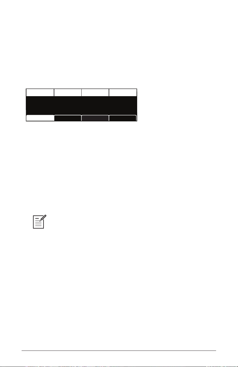
Master Volume/Program Volume
The master output level of the Pro 3 is controlled by the front-panel
master volume knob. In addition, the volume of an individual program
can be set with the volume parameter in the vca menu. This is useful for
ensuring that your sounds have roughly the same volume from program
to program.
Volume
127
VOLUME
VCA ADSRVCA VCA Env AmtFX
Setting Program Volume in the Amp Envelope menu
To set the volume of an individual program:
1. Choose a program.
2. Move any of the amp envelope controls on the front panel.
3. In the display menu, press Soft Button 1.
4. Turn Soft Knob 1 (volume) to adjust the volume level as desired.
5. Press the write button twice to save the program.
MIDI volume can also inuence the overall volume of the Pro 3 if you are
controlling it from an external MIDI source.
Master Volume/Program Volume
82
Sequential
Page 95
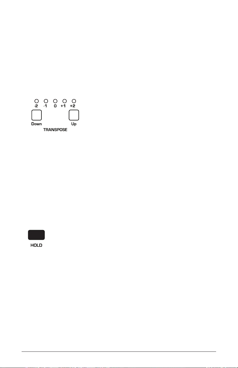
Transpose
The up and down buttons in the transpose section transpose the
keyboard up or down in octaves. The LED indicates the current
keyboard transposition state. Transposing the keyboard also changes the
MIDI note numbers of the keys so that MIDI notes sent are also transposed. Transpose settings are global and are not saved with individual
programs.
The Transpose controls
Hold
When hold is on, any notes played will continue to play until hold is
turned off. When used in conjunction with the Arpeggiator, notes are
latched on. If hold is on and at least one key continuously held down,
any new notes played are added to the arpeggio.
The Hold button
Glide
Glide causes the pitch of a note to glide up or down from the pitch of
the previously played note. Glide is turned on and off using the glide
switch, but the rate must also be set. If the glide button is on, but rate is
set to 0, glide has no effect. Glide can be set individually for each oscillator.
Pro 3 User’s Guide
Transpose
83
Page 96

Instr 1 Instr 2
Press to enable Glide
The Glide button
To use Glide:
1. Press the glide button to turn Glide on.
2. Play a series of notes up and down the keyboard while you turn the
glide amount knob to adjust the amount of glide.
Glide Modes
There are four modes that determine how glide behaves:
Fixed Rate: The time to transition between notes varies with the interval
between the notes; the greater the interval, the longer the transition time.
The glide rate is xed. This is the default glide mode.
Fixed Rate A: The same as Fixed Rate, but glide is only applied when
playing legato. That is, glide only occurs when a note is held until the
next note is played. This effectively allows glide to be turned on and off
from the keyboard.
84
Fixed Time: Glide is set to a xed time, regardless of the interval
between notes.
Fixed Time A: The same as Fixed Time, but glide only occurs when
playing legato.
To select a Glide Mode:
1. Press the glide button.
2. In the display menu, use Soft Knob 1 to choose the desired Glide
Mode.
3. Play a series of notes up and down the keyboard to hear the effect.
Glide
Sequential
Page 97

Glide Rate Osc 2 GlideOsc 1 Glide Osc 3 Glide
Choose a Glide
mode here
Choosing a Glide mode
Fixed Rate
GLIDE MODE
Key Modes Glide Pitch Wheel
14 14
OSC 1 GLIDE
14
OSC 2 GLIDE
OSC 3 GLIDE
To set the Glide Amount separately for each oscillator:
1. Press the glide button.
2. Play a series of notes up and down the keyboard while you turn Soft
Knobs 1-3 to adjust the amount of glide for individual oscillators.
Glide Rate Osc 2 GlideOsc 1 Glide Osc 3 Glide
Fixed Rate
GLIDE MODE
Key Modes Glide Pitch Wheel
Glide parameters
14 14
OSC 1 GLIDE
14
OSC 2 GLIDE
OSC 3 GLIDE
Pro 3 User’s Guide
Glide
85
Page 98

Pitch and Mod Wheels
The Pro 3 has a spring-loaded Pitch wheel and a Mod wheel. You can use
these controls to enhance live performance by bending notes and adding
modulation in real time as you play.
PITCH MOD
The Pitch and Modulation wheels
Pitch Wheel
You can set a range in semitones for the Pitch wheel, depending on your
playing preference. The upward range is 12 semitones (1 octave). The
downward range is 24 semitones (2 octaves). Many musicians use a
range of 2 semitones (a whole step) since this is the bend range of many
acoustic instruments. For guitar whammy bar effects, you many wish to
set a wider range.
To set the pitch bend range:
1. Press the misc params button and press Soft Button 3 (pitch wheel).
Button 3
2. Use Soft Knob 1 (range up) to set the range in semitones of the upward
bend.
3. Use Soft Knob 2 (range down) to set the range in semitones of the
downward bend.
4. Hold a note and move the Pitch wheel to hear the effect.
Pitch and Mod Wheels
86
Sequential
Page 99

Modulation Wheel
The Mod wheel controls the amount of modulation for any program that
uses it as a modulation source. This allows you to “perform” modulation in
real time by moving the wheel. This is a great way to add expressiveness
to a sound or performance by using it to control vibrato, lter effects, and
potentially a lot more.
To choose a modulation destination for the Mod wheel:
1. In the modulation section, press the source button. Use Soft Knob 1 to
scroll to Mod Slot 1 if it’s not already displayed.
2. Use Soft Knob 2 to scroll through the various mod sources and choose
mod wheel.
3. Use the Soft Knob 4 to scroll through the various mod destinations and
choose a parameter (such as cutoff).
4. Hold down a note on the keyboard (or press the hold button and play a
note on the keyboard) and turn the Mod wheel.
5. Use the Soft Knob 3 to set the modulation amount to your preference.
Higher amount settings add greater modulation the further you push
the Mod wheel. A negative amount setting will apply modulation in the
negative direction.
As a shortcut, you can hold down the source button and move the Mod wheel
to quickly assign this modulation path.
Mod 1
Mod 2
Mod 3
Mod 4
Slider
LFO 2t
Aftertouch
Mod Wheel
Sort SourceSlot Sort
Pro 3 User’s Guide
60
35
25
80
Sort Dest
DestinationEdit Mod 1 Source Amount
Cuto
Osc1 Shape
Drive
LFO1 Amt
Pitch and Mod Wheels
87
Page 100
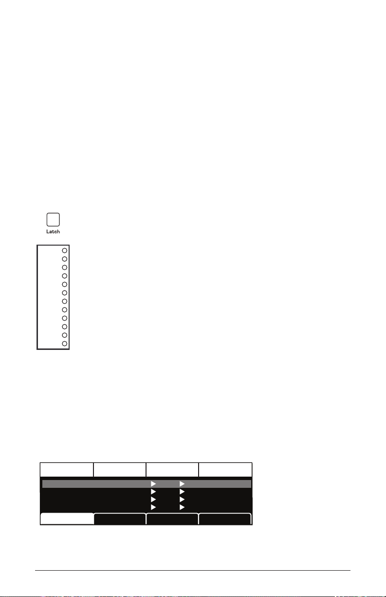
Touch slider
The Pro 3 has a position-sensitive Touch slider. Like the Pitch and Mod
wheels, you can use this slider to enhance live performance by adding
modulation in real time as you play.
The slider serves as a modulation source, the value of which is deter-
mined by nger position. The Touch slider appears in the modulation
matrix as slider. (See page 120 for a list of mod destinations.)
Normally, the slider affects the assigned modulation destinations only
while it’s being touched. But when latch is on, the Touch slider holds
the value from the position at which it was last touched.
TOUCH
The Touch slider
Use the mod matrix to assign modulation destinations to the slider. You
can route multiple modulation destinations to the slider. To display the
modulation matrix, press the source or destination buttons in the Modu-
lation section. Modulation slots and routings appear in the display.
DestinationEdit Mod 1 Source Amount
Cuto
Osc1 Shape
Drive
LFO1 Amt
Sequential
88
Mod 1
Mod 2
Mod 3
Mod 4
Touch slider
Slider
LFO 2t
Aftertouch
Mod Wheel
Sort SourceSlot Sort
60
35
25
80
Sort Dest
 Loading...