

Page 1

11436 Sorrento Valley Road, San Diego CA 92121 USA • 858-202-3100 • Fax 858-558-1915
Service Manual for SeQual
Integra Oxygen Concentrators
Part Number 2435
Revision H
SeQual Technologies Inc
San Diego, CA USA
Page 2

Service Manual
Integra Oxygen Concentrators
Table of Contents
Routine Patient Maintenance.....................................................................................3
Scheduled Preventive Maintenance...........................................................................3
Troubleshooting Guide ..............................................................................................4
Operational problems...........................................................................................4
Power problems ...................................................................................................5
Digital Error Code Guide...........................................................................................6
Service Section Compressor Assembly.....................................................................8
Compressor maintenance.....................................................................................8
Compressor Rebuild Procedure ...........................................................................8
Service Section Pod Assembly..................................................................................10
Board Calibration Procedure ...............................................................................10
Pod Replacement Procedure................................................................................12
ATF Replacement Procedure.....................................................................................13
Compressor Inlet Filter Replacement........................................................................13
Replacement Parts......................................................................................................14
Integra Technical Data...............................................................................................15
How to Contact SeQual .............................................................................................18
SeQual Technologies Inc. Page 2 of 18
San Diego, CA USA Part Number 2435
Page 3

Service Manual
Integra Oxygen Concentrators
Routine Patient Maintenance
At least once a week clean cabinet intake filter, located on the top of the unit.
1. Remove the filter from the cabinet.
2. Wash the filter in warm water using a mild detergent solution.
3. Rinse the filter thoroughly and squeeze out the excess water.
4. Allow the filter to air dry. Caution: The filter should be completely dry before
using it again, as excess moisture may impair the proper operation of the oxygen
concentrator.
5. Reinsert the filter in the cabinet.
The cabinet intake filter should be replaced as needed. If the Oxygen
Concentrator is used in a dusty environment, the filter may need to be replaced
more often. Do Not operate the Oxygen Concentrator for more than 30 minutes
without a filter installed.
Scheduled Preventive Maintenance
12 Months or as needed:
♦ Verify proper oxygen concentration. It should be a minimum of 88% at maximum
rated flow. While monitoring the concentration, verify that the LED’s function
properly. Refer to Troubleshooting Guide for further information.
♦ Clean inside the unit, as needed using a small vacuum cleaner to remove any
accumulation of dust or debris.
♦ Replace the compressor intake filter after 10,000 hours of operation or as needed (refer
to Troubleshooting Guide). Refer to Replacement Parts section for proper filter.
SeQual Technologies Inc. Page 3 of 18
San Diego, CA USA Part Number 2435
Page 4
Service Manual
Integra Oxygen Concentrators
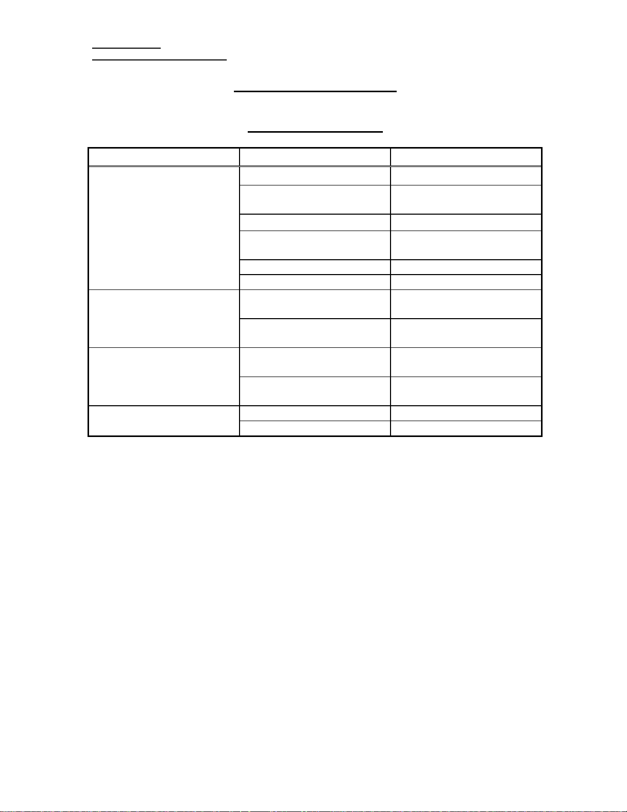
Problem Probable Cause Remedy
Troubleshooting Guide
Operational problems
Dirty cabinet intake filter. Clean or replace filter.
Concentration is below
specification.
Yellow LED is on.
Red LED is on and alarm is
sounding.
Pressure relief valve
purging.
Dirty compressor intake
Replace filter.
filter.
Flow above rated capacity. Check and adjust flow.
Worn compressor. Check compressor according
to Service Section.
Internal leak. Refer to Service Section.
Faulty ATF module. Refer to Service Section.
Concentration below 85%. See low concentration
above.
Oxygen sensor needs
Refer to Service Section.
calibrating.
Concentration below 70%. See low concentration
above.
Oxygen sensor needs
Refer to Service Section.
calibrating.
Faulty oxygen module. Refer to Service Section.
Faulty relief valve. Replace valve.
SeQual Technologies Inc. Page 4 of 18
San Diego, CA USA Part Number 2435
Page 5

Service Manual
Integra Oxygen Concentrators
Problem Probable Cause Remedy
Unit does not turn on.
Circuit breaker tripped.
Red LED is blinking and
alarm is beeping.
Power problems
Unit not connected to power
outlet.
Unit connected but not on. Check for switched outlet or
Circuit breaker tripped. Reset circuit breaker.
Circuit board malfunction. Refer to Service Section.
Power outage. Check outlet.
Excessive internal
temperature
Power interruption. Reset circuit breaker.
Unit started under pressure. Reset circuit breaker and
Faulty internal component. Refer to Service Section.
Low mains alarm due to
loss of power.
Excessive internal
temperature
Connect power.
tripped breaker in building.
Check for vent blockage or
faulty fan.
Allow unit to cool.
wait for flow meter to drop
to zero before turning on.
Depress power button, reset
circuit breaker and turn unit
on.
Check for vent blockage or
faulty fan.
Allow unit to cool.
SeQual Technologies Inc. Page 5 of 18
San Diego, CA USA Part Number 2435
Page 6

Service Manual
Integra Oxygen Concentrators
Digital Error Code Guide
In the event there is a malfunction during normal operations of the Concentrator, an Error
Code will be displayed on the LCD. These Error Codes, their probable causes, and the
suggested corrections are tabulated below.
User Related Error Codes
Error Code
Probable Cause Remedy
151
139; 141; 151; 153
174; 177
Flow rate too low.
Flow rate too high.
Unit is hot, insufficient
ventilation; blocked air
intake or air exhaust.
Increase flow rate. If
problem persists, verify
prescription and/or reset
limits. Refer to the section
on “Board Diagnostic
Procedure”.
Decrease flow rate. If
problem persists, verify
prescription and/or reset
limits. Refer to the section
on “Board Diagnostic
Procedure”.
Shut off unit.
Remove any obstruction(s)
from air openings (refer to
section “The Proper
Location” in the Instruction
Manual P/N 2668) and
allow unit to cool.
Restart unit.
184
Blocked Oxygen flow.
Shut off unit and find
obstruction to outlet.
Unkink outlet hose.
Replace humidifier.
Restart unit.
SeQual Technologies Inc. Page 6 of 18
San Diego, CA USA Part Number 2435
Page 7

Service Manual
Integra Oxygen Concentrators
Error Code Probable Cause Remedy
136; 208
158
152
Microprocessor Related Error Codes
Error Code Probable Cause Remedy
45; 142; 143; 146 – 148;
155 – 157; 159; 165;
171 – 173; 175; 176;
181 – 183; 185; 186;
204 – 207; 209; 210
1 − 19; 22 − 40; 46 – 49;
130; 150; 161 - 162; 170;
180; 190 - 191; 215 – 230
Service Related Error Codes
Abnormal Power
fluctuation.
Concentration too low.
Concentration warning.
Oxygen concentration did
not reach operational level.
Flow rate too high.
Incorrect calibration.
Processor error.
Check power source.
If problem persists, reset
limits. Refer to the section
on “Board Diagnostic
Procedure”.
Check for leaks among the
hoses and fittings. If none
found, check the Oxygen
Sensor. If Sensor reads
correctly, check for worn
compressor. (Rebuild
compressor if necessary.)
If compressor is all right,
replace the ATF.
Turn flow rate adjustment
knob clockwise until full
stop (closed); then turn knob
counterclockwise one full
turn. If problem persists, see
steps above for Error # 158.
Unit needs to go through the
complete Diagnostic
Procedure. Refer to the
section on “Board
Diagnostic Procedure”.
Shut off unit.
Restart unit after 3 minutes.
If problem persists, contact
SeQual Technical Service.
SeQual Technologies Inc. Page 7 of 18
San Diego, CA USA Part Number 2435
Page 8

Service Manual
Integra Oxygen Concentrators
Service Section
Remove the covers from the unit by removing the four screws in the sides and one in the
handle. Spread the covers apart from the top and lift them off.
Compressor Assembly
Compressor maintenance
1) Remove the pressure relief valve from the compressor and install a pressure gauge
using a ¼” NPT male fitting with a hose connection (SeQual Part No 9151).
2) Turn on the unit, set the flow meter at rated flow and check the compressor pressure.
If it is below 18 psig, then check for leaks around the compressor fittings and hoses
using Snoop or equivalent leak detection fluid. If no leaks are found, replace the air
inlet filter. If the pressure is still below 18 psig, then rebuild the compressor; refer to
compressor rebuild section.
3) Inspect the spring mounts for uneven wear or damage. Replace spring mounts if
necessary using the procedure in the next section.
Compressor Rebuild Procedure
Refer to Replacement Parts Section for proper rebuild kit. Contact Sequal for all other
compressor accessories.
1) Disconnect the power from the unit.
2) Remove the air inlet hose from the barb fitting on the compressor. Leave the fitting
in place.
3) Remove the heat exchanger coil from the tube fitting. Leave the fitting in the
compressor head.
4) If replacing the spring mounts, do so at this time. Otherwise, go to Step 6. Remove
the two inspection plates on the bottom of the unit and unscrew the four compressor
retaining bolts. Lift the compressor off.
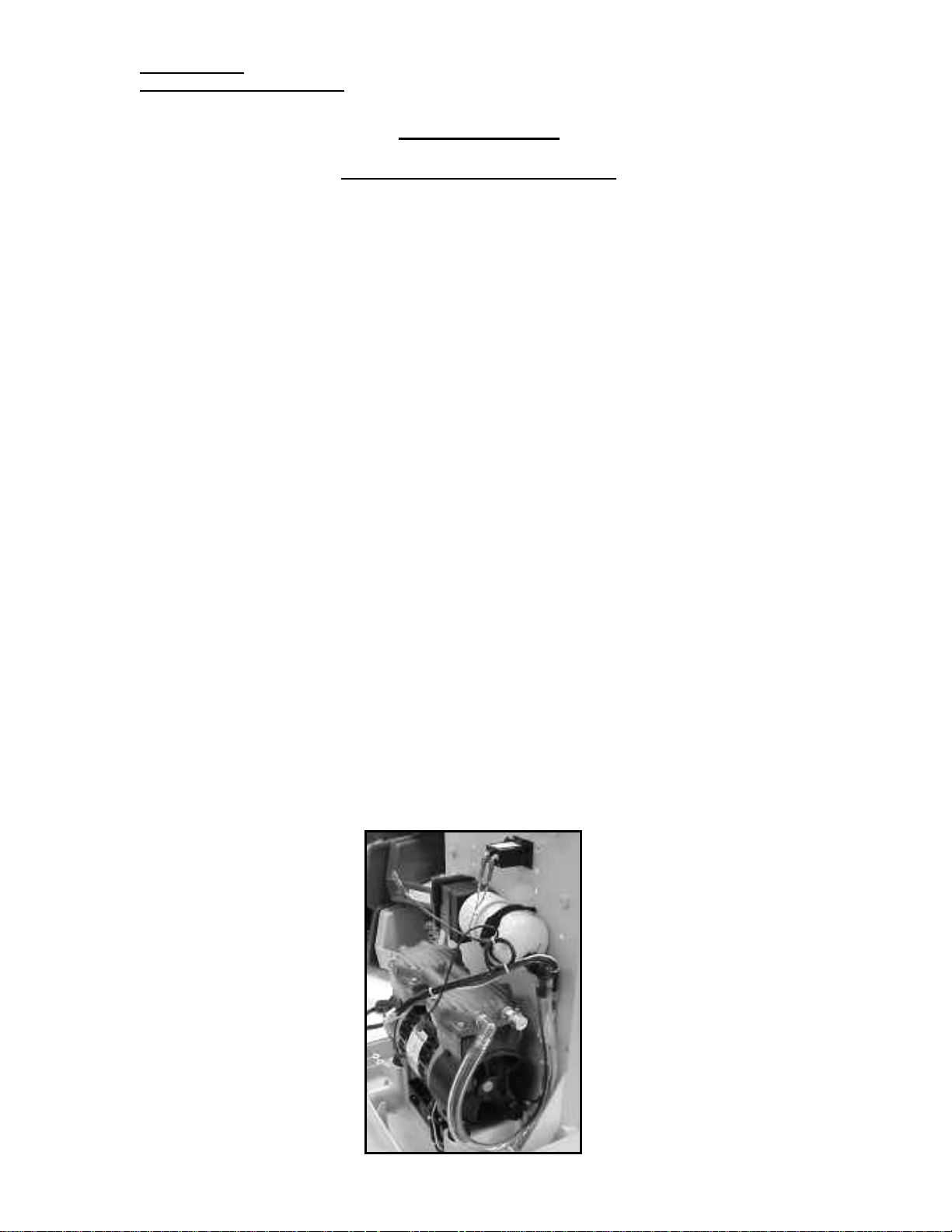
5) If not rebuilding the compressor, place it on the new
spring mounts with the springs oriented as shown in the
picture. Be sure the large end of the spring is fully inside
the cup on the base. Replace rubber washers on bolts,
apply thread locker to the four bolts and install through
the mounts and tighten to 36 in-lbs. Install the inspection
plates and tighten the screws until they bottom out on the
plate.
6) Mark the heads with a felt pen to ensure that the head and valve plate are re-installed
on the cylinder that they were removed from.
7) Remove the cap screws on the heads and pull up on the head and valve plate
assembly. Refer to the exploded view in the parts kit.
SeQual Technologies Inc. Page 8 of 18
San Diego, CA USA Part Number 2435
Page 9
Service Manual
Integra Oxygen Concentrators
Service Section
Compressor Assembly (continued)
8) Separate one of the valve plates from the head and remove and discard the O-ring
seals.
9) Note the orientation of the valves and remove the valve screws and limiters (if
applicable).
10) Clean any residue from the valve plate using a water based solvent.
11) Install new valves and limiters (if applicable) in the orientation noted in step 7.
Torque screws 10-13 in-lbs.
12) Repeat steps 6-9 for the other valve plate assembly.
13) If not rebuilding the cylinders go to step 19.
14) Remove the piston screws.
15) Remove the cylinder sleeve, retainer plate and piston cup.
16) Place the new cup on the rod, facing up.
17) Install retainer plate and torque screws 34-38 in-lbs.
18) Rotate the compressor until the rod is at its topmost position.
19) Install the sleeve at a 45° angle over part of the retainer. Carefully work the sleeves
down over the cup until it is level with the cup.
20) Repeat steps 12-17 for the other cylinder.
21) Replace cylinder O-rings in the bottom of the valve plate.
22) Set the cylinder assembly down into the compressor body, making sure to properly
seat the sleeves in the notches of the body.
23) Position the valve plates over the cylinders, lining up the cylinder O-ring with the
sleeve and the marks made in step 4.
24) Install the head O-rings and position the head over the valve plate, again lining up
the marks.
25) Torque the head screws, working outer to inner, to 48-50 in-lbs.
26) Install the heat exchanger and air inlet hose.
27) If the compressor was removed, re-install according to Step 5 above, using the
picture below for proper installation orientation.
SeQual Technologies Inc. Page 9 of 18
San Diego, CA USA Part Number 2435
Page 10
Service Manual
Integra Oxygen Concentrators
Service Section
Pod Assembly
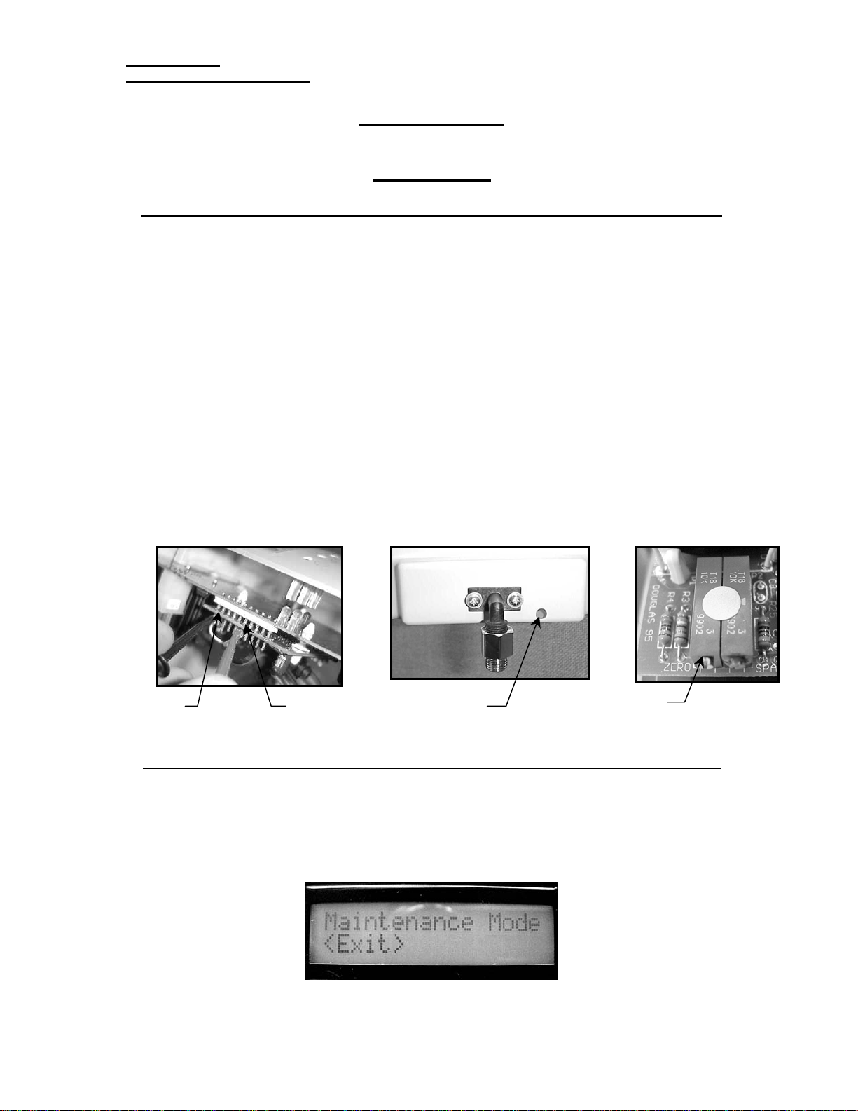
Board Diagnostic Procedure 5 and 10 Liter Analog Models with Oxygen Monitor
1) Turn unit off and remove the covers.
2) Connect an Oxygen Sensor to the outlet according to the Sensor manufacturer
recommendations.
3) Connect a voltmeter to pins one and six of the sensor board.
4) Turn on the unit and adjust the flow on the flow meter to the appropriate flow setting
for the unit under test.
5) Allow the unit to run for five minutes before making any adjustments. If the unit
shuts down before the warm up time has elapsed, then replace the Pod assembly (see
next section).
6) Compare the concentration value on the Oxygen Sensor to the value on the
voltmeter. If they are within + 2% and are stable, then no adjustment is necessary.
7) If they are out of range, adjust the pot on the sensor. It can be reached with a small
thin screwdriver, through the adjustment hole on the front of the pod.
8) Turn the pot until the values are equal.
9) If it does not adjust or the value is unstable, replace the Pod assembly.
Pin #1 Pin #6 Insert Screwdriver
Adjust this screw
Board Diagnostic Procedure 5 and 10 Liter Digital Models with Oxygen Monitor
1) Turn unit off and remove the covers.
2) Connect an Oxygen Sensor to the outlet according to the Sensor manufacturer
recommendations.
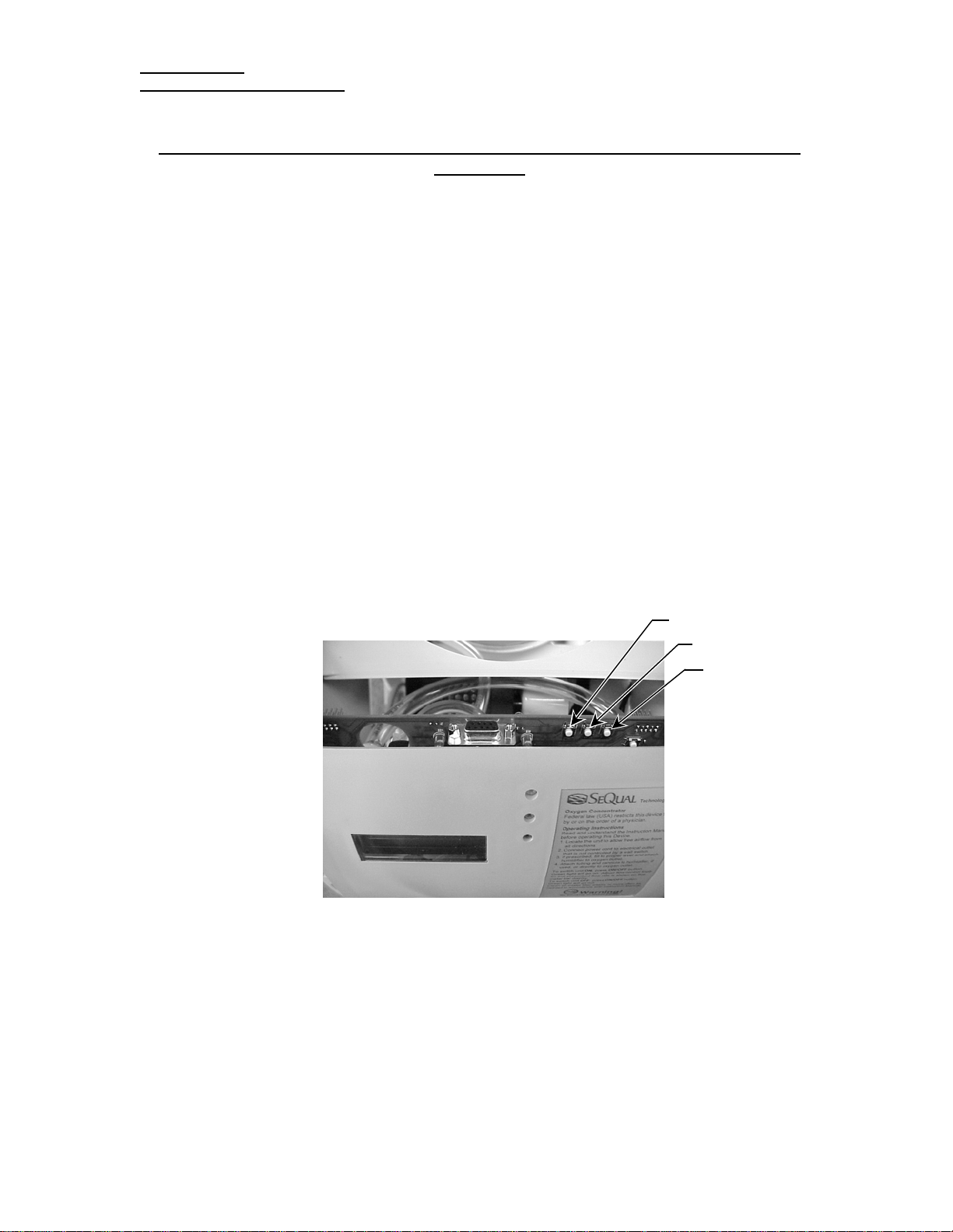
3) Locate the push buttons on the top back of the circuit board.
SeQual Technologies Inc. Page 10 of 18
San Diego, CA USA Part Number 2435
Page 11
Service Manual
Integra Oxygen Concentrators
Board Diagnostic Procedure 5 and 10 Liter Digital Models with Oxygen Monitor
(continued)
4) Press the center button and “Maintenance Mode” will be displayed on the top line of
the LCD display. Repeated pressing of the center button will toggle the unit through
the various maintenance mode settings. Where applicable, the right button (when
viewing from the front) changes the settings. These are:
a) Hour Log - displays the total run time of the concentrator.
b) Version - displays the software version of the concentrator.
c) Flow Limit - displays the maximum allowable flow setting, per patient
prescription, and can be adjusted by the technician in 0.5 LPM increments, using
the right button.
d) Language - displays the current language setting, and allows the technician to
toggle between the three language choices, using the right button.
e) Show Fault - displays the last saved fault number and allows the technician to
clear the fault, using the right button.
f) Fault Override - allows the technician to select “halt on fault” or “ignore faults”.
g) Flow - displays the oxygen flow.
h) Concentration - displays the oxygen concentration.
i) Gas Temp - displays the temperature of the oxygen in degrees centigrade.
j) Ambient Temp - displays the room temperature in degrees centigrade.
k) Gas Pressure - displays the pressure of the oxygen.
l) Line Voltage - displays the line input voltage.
Left Button
Center Button
Right Button
5) Press the center button until Flow Limit: is displayed. Press the button to the right
(when viewing the front) until the maximum flow rate is displayed.
6) Allow the unit to warm up and achieve stable concentration (about 5 minutes).
7) Press the center button until Conc: is displayed. Compare the concentration value on
the display to that of the oxygen monitor. If the difference is more than 1.0%, contact
SeQual for a replacement pod.
8) When finished monitoring the concentration, press the button to the left (when viewing
the front) to exit Maintenance Mode.
SeQual Technologies Inc. Page 11 of 18
San Diego, CA USA Part Number 2435
Page 12
Service Manual
Integra Oxygen Concentrators
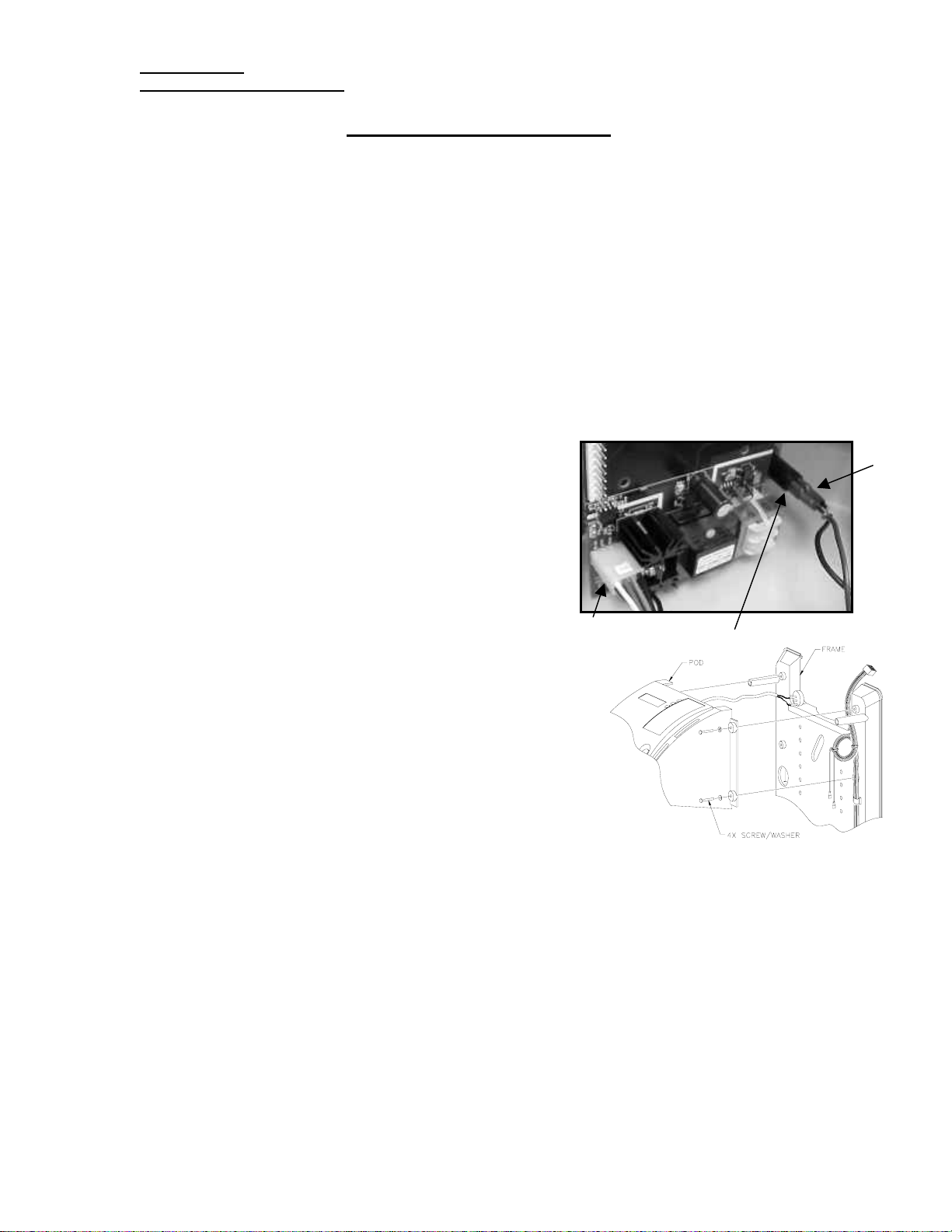
Pod Replacement Procedure
1) Disconnect power from the unit.
2) Remove the hose from the HEPA filter outlet and temporarily seal the barb on the
filter (using tape or a cap) in order to keep the filter clean.
3) (For digital models only) Remove the alarm from the center frame. Be sure to
remove all excess tape form the center frame. If necessary use isopropyl alcohol to
clean the surface.
4) Remove the four screws holding the Pod assembly to the frame (see sketch below),
holding the Pod to prevent it from falling.
5) Turn the Pod over and disconnect the wires (T1 and T2) from the circuit breaker and
disconnect the eight-pin plug (J501) by depressing the catch lever and pulling the
connector.
6) Holding the new Pod close to the final installation position rotate the face downward
in order to hook-up the following connectors:
a) Connect wire harness 8-pin connector (J501)
to PCA. Align the clip side of the connector
with the PCA connector having the catch
(bump) on
b) Connect the black or brown wire terminal (T1)
to the bottom connector tab on the circuit
breaker.
c) Connect the brown wire terminal (T2) to the
top connector tab on the circuit breaker.
Rotate the Pod upright and align the four attachment
points (see sketch) with the appropriate holes on the
center frame and push into place. Secure Pod to
Frame at each hole using 1 each Screw (2414) and
Washer (3026) pushed through the hole from the
Pod side of the frame. Secure on the backside of the
frame with 1 each Washer (3026) and Nut (2316).
Tighten screws with Phillips #1 Bit (For digital
models only). Mount the alarm in the curvature
toward the top left side of the center frame. Be sure
that the alarm opening is facing the back of the unit
as shown. Use the double-sided tape that is already applied to the alarm for securing
the alarm to the center frame. Make sure the mounting surface is clean. If necessary,
use isopropyl alcohol to clean the surface.
Route the loose end of PVC Tubing through the center frame angled oval opening.
Remove the seal from the ATF HEPA Filter Barb. Slide one Hose Clamp (2311 or
3228) over the loose tube just routed from the Pod. Push the end of the tube onto the
barb until it hits the stop. Position hose clamp behind step in barb.
Ensure all three Cable Clips that hold the wire harness on the center frame are pushed
closed and hold all wires. Replace if necessary.
the side.
J501
T2
T1
SeQual Technologies Inc. Page 12 of 18
San Diego, CA USA Part Number 2435
Page 13
Service Manual
r
Integra Oxygen Concentrators
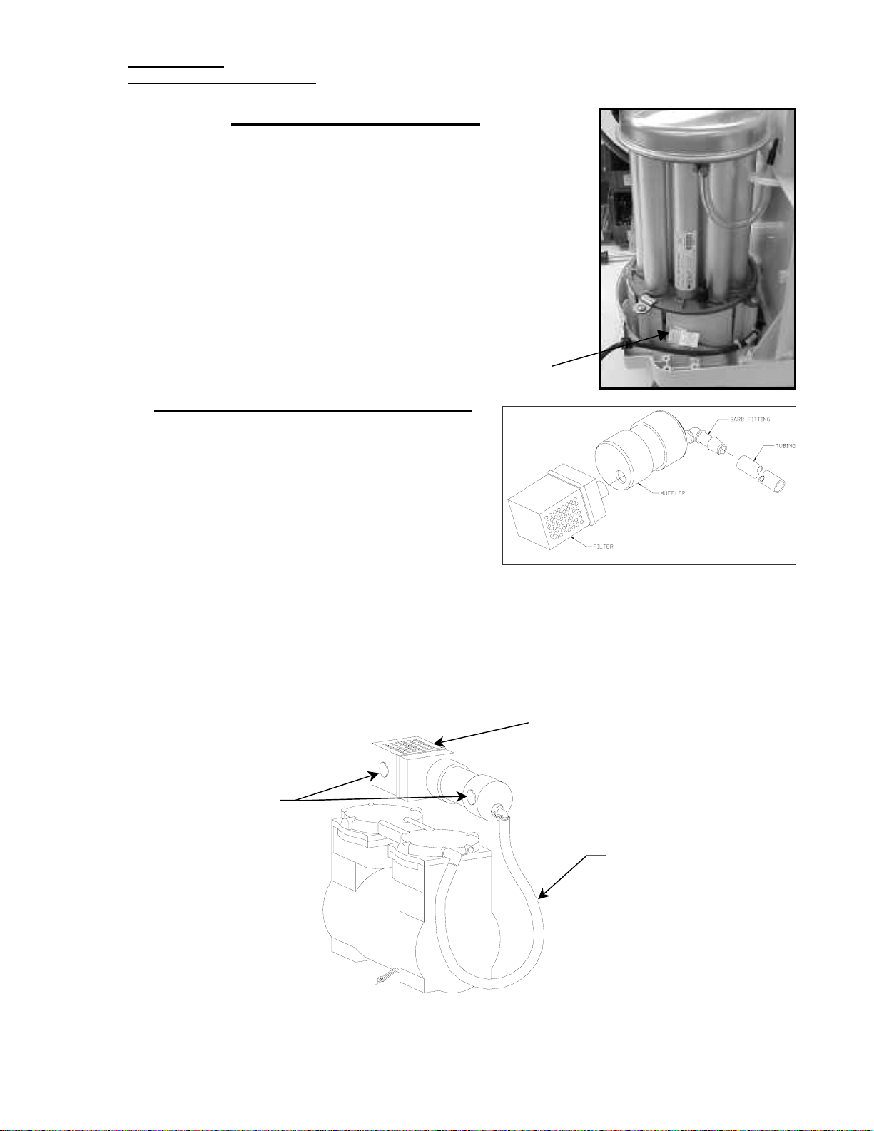
ATF Replacement Procedure
Disconnect the power connector, shown in the picture, by
pressing the locking tabs and pulling the housings apart.
Remove the four screws holding the toe clamps to the ATF.
Remove the two hoses from the ATF and cover the barbs
using the plastic caps from the new ATF. Do not leave the
barbs uncovered for more than five minutes. Lift the ATF
out of the basket. Set the new ATF in position as shown in
the picture. Attach the hoses and tighten the clamps to 100
in-oz. Install the toe clamps on the ATF and tighten the
screws to 20 in-lbs. Connect the power connector.
Compressor Inlet Filter Replacement
Remove the hook and loop straps from the
Filter/Muffler assembly. Hold the white
muffler and twist and pull the filter to remove it.
Insert outlet tube on Filter (2607) into the hole
on the Muffler. Rotate the filter so that the two
parts are roughly lined up across the top length.
Push the Filter into the Muffler until the two
parts touch.
Place the Filter/Muffler assembly in the installed position (as shown below and in
picture on page 9) and loop the straps over the assembly. Fasten the assembly by
securing the ends of both straps and ensuring that they both cover and attach to the
strap pads. Ensure the free end of the PVC Tubing is on the compressor Air Inlet
Fitting barb.
Power Connecto
Vent holes in filter to be on
top and bottom of
Filter/Muffler Assembly
Strap Pads
PVC Tubing
SeQual Technologies Inc. Page 13 of 18
San Diego, CA USA Part Number 2435
Page 14

Service Manual
Integra Oxygen Concentrators
Preventive Maintenance Parts
Description SeQual Part Number
Cabinet Intake Filter 2185 Compressor Inlet Filter 2607 HEPA Filter 2033 Compressor Rebuild Kit 3197, 3418 Pressure Gauge Test Fitting 9151
Recommended Spare Parts Inventory
Description SeQual Part Number
Pod Assembly
Compressor Assembly
ATF Module
Refer to Parts Manual or call for correct
replacement part. Specify Model Number
when ordering parts.
SeQual Technologies Inc. Page 14 of 18
San Diego, CA USA Part Number 2435
Page 15
Service Manual
(
)
Integra Oxygen Concentrators
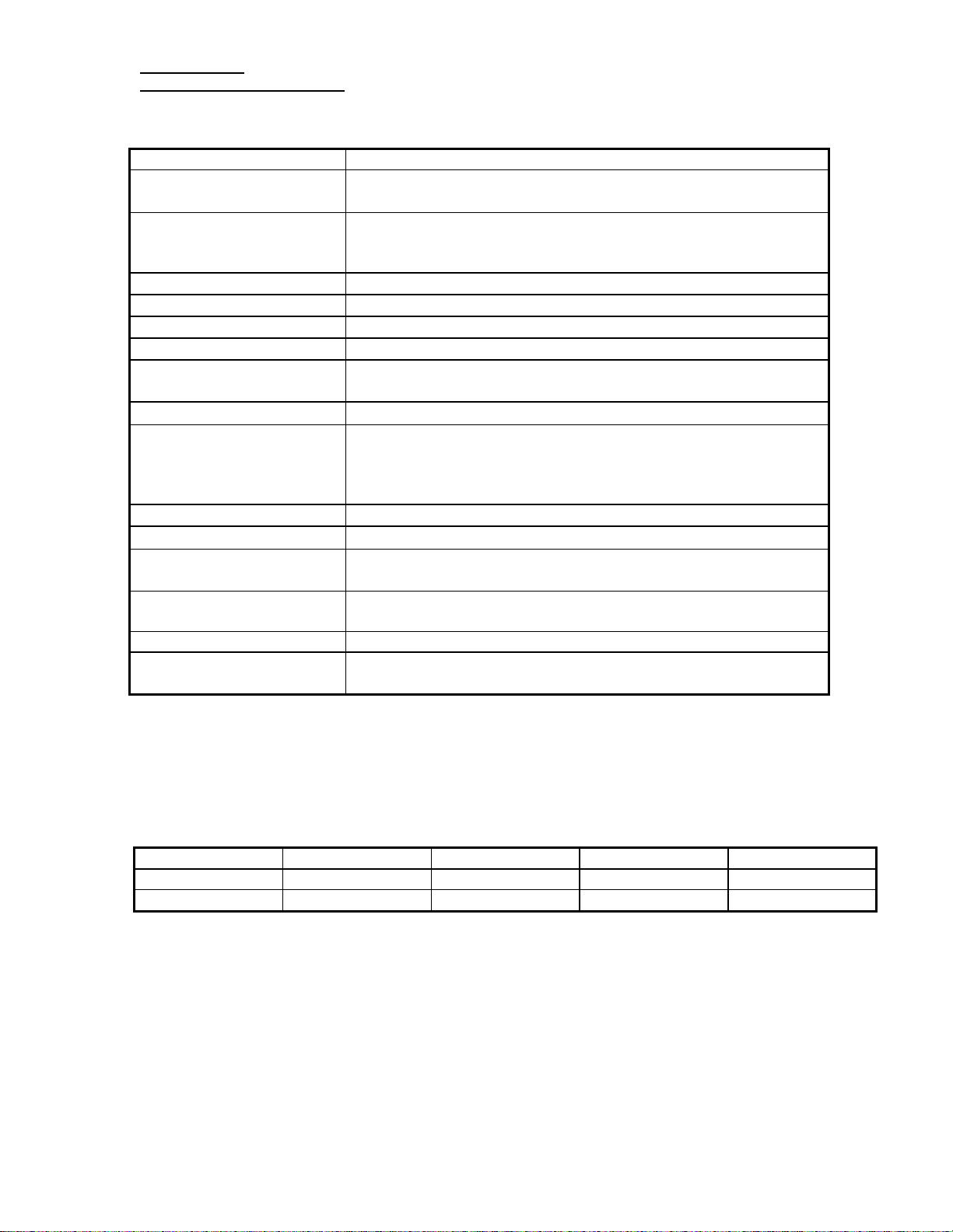
Integra Model Number 6323 / 6323OM Technical Data
Flow Rate 1 to 5 LPM
Oxygen Concentration
1 to 5 LPM 91 ± 3% at sea level
Oxygen Concentration
Indicator
Green Light = Normal Operation
Yellow Light = Below Normal Operation (85%*)
Red Light = Abnormal Operation (70%*)
Maximum System Pressure
Oxygen Outlet Pressure
Electrical Power
Operating Temperature
Dimensions (H x W x D)
27 psi (186.1 kPa)
Nominal 5.5 psi (37.9 kPa) - Maximum 11.0 psi (75.8 kPa)
110-120V~, 60Hz, 5.0A / 220-230V~, 50Hz, 2.4A
50° F to 104° F
10° C to 40° C
26.5 in. (67 cm) H × 14.7in. (37 cm) W × 19.5 in. (50 cm) D
Refer to label on back cover of unit for correct voltage setting.
Flow Indication
Audible Alarm Indicators
Ball Flow Meter (Ball Flow Meter accuracy is ±10%)
Power Interruption
Excessive Internal Temperature
Outlet Pressure [35-36 psig (241.2-248.1 kPa) relief valve]
Low Therapeutic Oxygen Output* <70% oxygen
Filters
Cabinet, Compressor Inlet and HEPA
Device Classification IEC Class II, Type BF Applied Part, Continuous Operation
Transport/Storage
Requirements
Backpressure Effect on
Flow Indicator
Temperature: -4° F (-20° C) to +140° F (+60° C)
Humidity: Up to 95% Non-Condensing
0 psi (0 kPa): 5.0 LPM
1 psi (7 kPa): 4.83 LPM
Sound Level < 60dBA (per ISO 8359, Clause 26.2)
OSCI Operation*
Temperature: 50° F to 104° F (10° C to 40° C) Independent of
Atmospheric Pressure.
*Where equipped, subject to ±3% system concentration accuracy, and for back pressures
up to 7kPa.
Variation of Performance at Altitude - Flow Set at 5 LPM (actual) (220-230V~, 50Hz)
Altitude ft. (m) 0 (0) 4000 (1219) 7000 (2133) 10,000 (3048)
Flow slpm 5.00 4.65 4.38 4.13
O2 Concentration % 93.7 93.2 92.9 91.4
SeQual Technologies Inc. Page 15 of 18
San Diego, CA USA Part Number 2435
Page 16

Service Manual
(
(
Integra Oxygen Concentrators
Integra Model Number 6323-7 / 6323OM-7 Technical Data
Flow Rate 1 to 7 LPM
Oxygen Concentration
Oxygen Concentration
Indicator
1 to 7 LPM 91 ± 3% at sea level
Green Light = Normal Operation
Yellow Light = Below Normal Operation (85%*)
Red Light = Abnormal Operation (70%*)
Oxygen Outlet Pressure
Electrical Power
Operating Temperature
Dimensions (H x W x D)
Flow Indication
Audible Alarm Indicators
Nominal 7.0 psig (48.2 kPa)
115V~, 60Hz, 5.0A
50° F to 104° F
26.5 in.
66 cm) H ×14.7in. (37 cm) W ×19.5 in. (50 cm) D
Ball Flow Meter (Ball Flow Meter accuracy is ±10%)
Power Interruption
10° C to 40° C)
1
- Maximum 11.0 psig (75.8 kPa)
Excessive Internal Temperature
Outlet Pressure [35-36 psig (241.2-248.1 kPa) relief valve]
Low Therapeutic Oxygen Output* <70% oxygen
Filters
Cabinet, Compressor Inlet and HEPA
Device Classification IEC Class II, Type BF Applied Part, Continuous Operation
Transport/Storage
Requirements
Back pressure Effect on
Flow Indicator
Temperature: -4° F (-20° C) to +140° F (+60° C)
Humidity: Up to 95% Non-Condensing
0 psig (0 kPa): 7 LPM
1 psig (7 kPa): 6.86 LPM
Sound Level < 60dBA (per ISO 8359, Clause 26.2)
OSCI Operation*
Temperature: 50° F to 104° F (10° C to 40° C) Independent of
Atmospheric Pressure.
* Where equipped. Subject to ±3% system concentration accuracy, and for backpressures
up to 7kPa.
1
Outlet pressure may decline to 5.0 psig (34.5 kPa) nominal at 10,000 ft altitude.
SeQual Technologies Inc. Page 16 of 18
San Diego, CA USA Part Number 2435
Page 17
Service Manual
(
(
Integra Oxygen Concentrators
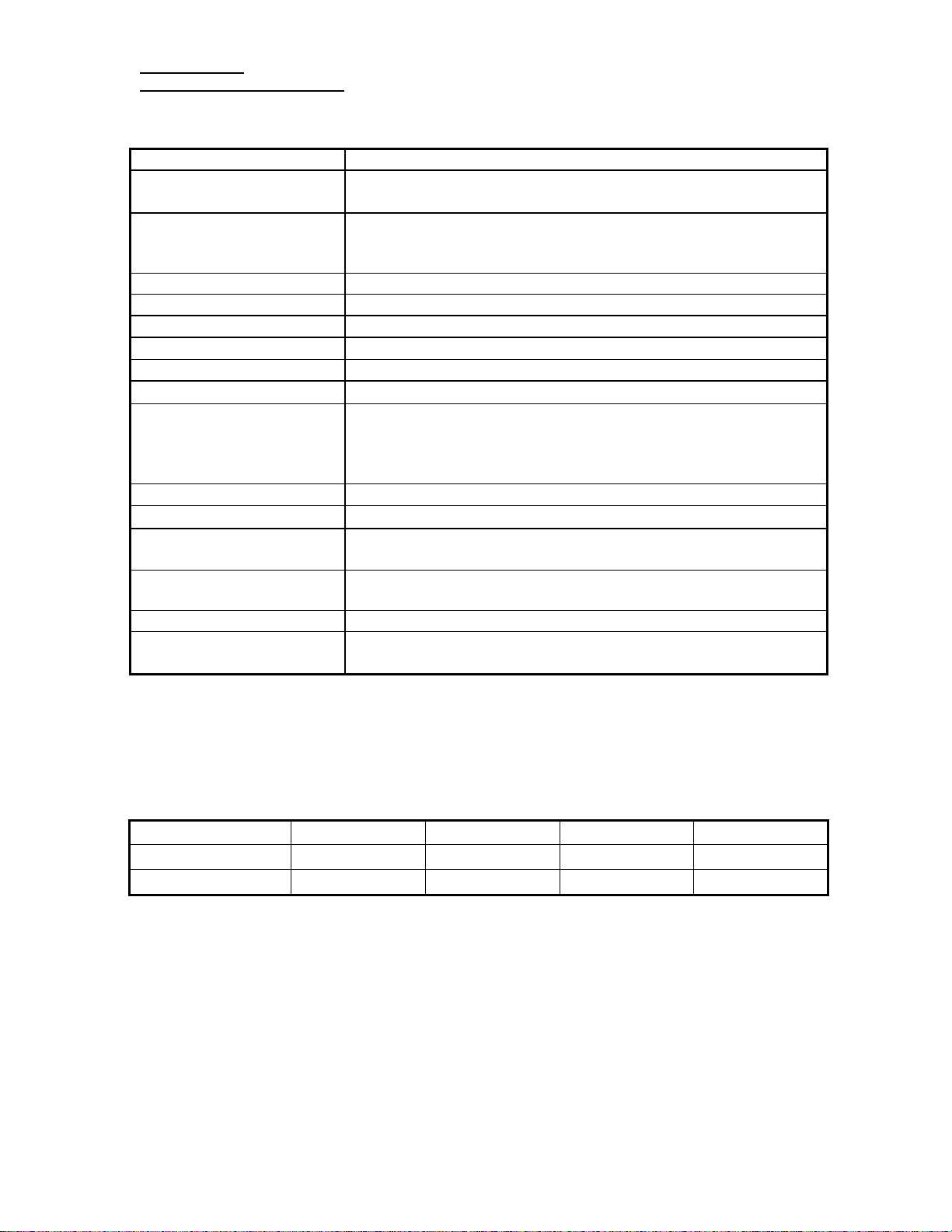
Integra Model Number 6323-10 / 6323OM-10 Technical Data
Flow Rate 1 to 10 LPM
Oxygen Concentration
Oxygen Concentration
Indicator
Maximum System Pressure 27 psig (186.1 kPa)
Oxygen Outlet Pressure
Electrical Power
Operating Temperature
Dimensions (H x W x D)
Flow Indication
Audible Alarm Indicators
Filters
Device Classification IEC Class II, Type BF Applied Part, Continuous Operation
Transport/Storage
Requirements
Back pressure Effect on
Flow Indicator
Sound Level < 60dBA (per ISO 8359, Clause 26.2)
OSCI Operation*
1 to 10 LPM 91 ± 3% at sea level
Green Light = Normal Operation
Yellow Light = Below Normal Operation (85%*)
Red Light = Abnormal Operation (70%*)
5.5 - 7.5 psig (37.9 – 51.7 kPa) at maximum rated flow
115V~, 60Hz, 5.0A, 220-230V~, 50Hz, 3.0A
50° F to 104° F
26.5 in.
Ball Flow Meter (Ball Flow Meter accuracy is ±10%)
Power Interruption
Excessive Internal Temperature
Outlet Pressure [35-36 psig (241.2-248.1 kPa) relief valve]
Low Therapeutic Oxygen Output* <70% oxygen
Cabinet, Compressor Inlet and HEPA
Temperature: -4° F (-20° C) to +140° F (+60° C)
Humidity: Up to 95% Non-Condensing
0 psig (0 kPa): 10 LPM
1 psig (7 kPa): 9.35 LPM
Temperature: 50° F to 104° F (10° C to 40° C) Independent of
Atmospheric Pressure.
66 cm) H ×14.7in. (37 cm) W ×19.5 in. (50 cm) D
10° C to 40° C)
*Where equipped. Subject to ±3% system concentration accuracy, and for back pressures
up to 7kPa.
Variation of Performance at Altitude (220-240V, 50Hz) – Flow Set at 10 LPM (actual)
Altitude ft. (m) 0 (0) 4000 (1219) 7000 (2133) 9000 (2743)
Flow slpm 10.0 9.3 8.7 8.4
O2 Concentration % 92.0 89.0 87.0 86.6
The performance will decline above 9000 ft (2743m).
SeQual Technologies Inc. Page 17 of 18
San Diego, CA USA Part Number 2435
Page 18

Service Manual
Integra Oxygen Concentrators
If you need any additional assistance, contact Customer Service.
By mail:
SeQual Technologies, Inc.
11436 Sorrento Valley Road
San Diego, CA 92121 USA
By telephone: 858-202-3100 or toll-free in the United States at 1-800-826-4610
By facsimile: 858-558-1915
By E-mail: [email protected]
SeQual Technologies Inc. Page 18 of 18
San Diego, CA USA Part Number 2435
 Loading...