

SEPTENTRIO AsteRx-U User Manual
AsteRx-U
User Manual

User Manual Version 1.0
Applicable to version 4.1.1 of the AsteRx-U Firmware
September 08, 2015
Thank you for choosing the AsteRx-U! This user manual provides detailed instructions
on how to use AsteRx-U and we recommend that you read it carefully before you start using
the device.
Please note that this manual provides descriptions of all functionalities of the AsteRxU product family however, the particular AsteRx-U you purchased may not support
functions specific to certain variants.
While we try to keep the manual as complete and up-to-date as possible, it may be
that future features, functionality or other product specifications change without prior
notice or obligation. The information contained in this manual is subject to change without
notice.
© Copyright 2000-2015 Septentrio NV/SA. All rights reserved.
Septentrio
Greenhill Campus, Interleuvenlaan 15G
B-3001 Leuven, Belgium
http://www.septentrio.com
support@septentrio.com
Phone: +32 16 300 800
Fax: +32 16 221 640
@Septentrio
2

LIST OF CONTENTS
List of Contents
1 Introduction 5
1.1 USER NOT ICE S . .. ... .. . .. ... .. . .. . .. .. . .. . .. .. . .. . .. ... .. . .. ... .. . .. ... .. . .. ... .. . .. . .. .. . .. . 5
1.1.1 CE Notice . ... .. . .. ... .. . .. ... .. . .. ... .. . .. ... .. . .. . .. .. . .. . .. ... .. . .. ... .. . .. ... .. . . 5
1.1.2 ROHS/WEEE Notice. .. . .. ... .. . .. ... .. . .. ... .. . .. . .. .. . .. . .. .. . .. . .. ... .. . .. ... .. . . 5
1.1.3 Safety information . .. . .. ... .. . .. ... .. . .. ... .. . .. ... .. . .. ... .. . .. . .. .. . .. . .. ... .. . . 5
1.1.4 Support . ... .. . .. ... .. . .. ... .. . .. ... .. . .. ... .. . .. . .. .. . .. . .. ... .. . .. ... .. . .. ... .. . .. . 6
2 AsteRx-U overview 7
2.1 ASTERX-U KE Y FE ATURES . . .. ... .. . .. ... .. . .. ... .. . .. ... .. . .. . .. .. . .. . .. ... .. . .. ... .. . .. ... . 7
2.1.1 GNSS . .. ... .. . .. ... .. . .. ... .. . .. . .. .. . .. . .. ... .. . .. ... .. . .. ... .. . .. ... .. . .. . .. .. . .. . . 7
2.2 ASTERX-U VARIANTS . .. ... .. . .. ... .. . .. . .. .. . .. . .. ... .. . .. ... .. . .. ... .. . .. ... .. . .. . .. .. . .. . . 9
2.3 ASTERX-U DE SIG N .. ... .. . .. ... .. . .. . .. .. . .. . .. ... .. . .. ... .. . .. ... .. . .. ... .. . .. ... .. . .. . .. .. 10
2.3.1 Front panel . .. . .. ... .. . .. . .. .. . .. . .. ... .. . .. ... .. . .. ... .. . .. ... .. . .. ... .. . .. . .. .. . .. 10
2.3.2 LED description . . .. ... .. . .. ... .. . .. ... .. . .. ... .. . .. . .. .. . .. . .. ... .. . .. ... .. . .. ... .. 11
2.3.3 Rear panel . . .. . .. ... .. . .. ... .. . .. ... .. . .. ... .. . .. ... .. . .. . .. .. . .. . .. .. . .. . .. ... .. . .. 12
2.3.4 SIM card slot . ... .. . .. . .. .. . .. . .. ... .. . .. ... .. . .. ... .. . .. ... .. . .. . .. .. . .. . .. .. . .. . .. 12
2.3.5 Mounting brackets . .. . .. . .. .. . .. . .. ... .. . .. ... .. . .. ... .. . .. ... .. . .. ... .. . .. . .. .. . . 13
2.3.6 Internal memory .. . .. ... .. . .. ... .. . .. ... .. . .. ... .. . .. ... .. . .. . .. .. . .. . .. ... .. . .. .. 13
2.4 SHIPPING CA SE CON TEN TS . .. ... .. . .. ... .. . .. ... .. . .. ... .. . .. . .. .. . .. . .. ... .. . .. ... .. . .. ... 14
2.4.1 Supplied as standard . .. . .. . .. .. . .. . .. ... .. . .. ... .. . .. ... .. . .. ... .. . .. ... .. . .. . .. . 14
2.4.2 Optional items .. .. . .. . .. ... .. . .. ... .. . .. ... .. . .. ... .. . .. ... .. . .. . .. .. . .. . .. ... .. . .. 15
3 Quick start 16
3.1 POW ERI NG T HE AS TERX-U .. .. . .. ... .. . .. ... .. . .. ... .. . .. ... .. . .. . .. .. . .. . .. ... .. . .. ... .. . . 16
3.2 CON NEC TIN G AN ANT ENN A .. .. . .. ... .. . .. ... .. . .. ... .. . .. . .. .. . .. . .. ... .. . .. ... .. . .. ... .. . 17
3.3 CON NEC TIN G TO THE ASTERX-U VIA TH E WEB INTE RFACE . .. . .. ... .. . .. ... .. . .. . .. .. . .. 17
3.3.1 Using the USB cable . .. . .. . .. .. . .. . .. ... .. . .. ... .. . .. ... .. . .. ... .. . .. ... .. . .. . .. .. 17
3.3.2 Using the Ethernet cable . .. . .. ... .. . .. ... .. . .. ... .. . .. . .. .. . .. . .. .. . .. . .. ... .. . .. 19
3.3.3 Over Wi-Fi .. . .. ... .. . .. ... .. . .. . .. .. . .. . .. ... .. . .. ... .. . .. ... .. . .. ... .. . .. . .. .. . .. . . 20
3.4 HOW TO CON FIG URE SBF AND NMEA OUT PUT . .. ... .. . .. ... .. . .. . .. .. . .. . .. ... .. . .. ... . 21
3.4.1 Output over a serial COM connection . ... .. . .. ... .. . .. ... .. . .. ... .. . .. . .. .. . .. . 21
3.4.2 Output over Ethernet . .. . .. .. . .. . .. ... .. . .. ... .. . .. ... .. . .. ... .. . .. ... .. . .. . .. .. . . 25
3.4.3 Output over bluetooth . . .. . .. .. . .. . .. .. . .. . .. ... .. . .. ... .. . .. ... .. . .. ... .. . .. . .. . 28
4 Common Configurations 32
4.1 HOW TO CON FIG URE THE ASTERX-U FOR RTK . ... .. . .. ... .. . .. . .. .. . .. . .. ... .. . .. ... .. . . 32
4.1.1 How to configure the AsteRx-U in RTK rover mode using the UHF radio . . 32
4.1.2 How to configure the AsteRx-U in RTK rover mode using the cellular
modem and NTRIP . .. . .. ... .. . .. ... .. . .. ... .. . .. ... .. . .. . .. .. . .. . .. ... .. . .. ... .. . . 35
4.1.3 How to configure the AsteRx-U in RTK rover mode using TCP/IP in a
closed network . ... .. . .. ... .. . .. ... .. . .. . .. .. . .. . .. ... .. . .. ... .. . .. ... .. . .. ... .. . .. 39
4.2 HOW TO CON FIG URE THE ASTERX-U AS AN RTK BASE STATION . .. . .. ... .. . .. ... .. . .. . . 43
3

LIST OF CONTENTS
4.3 HOW TO CON FIG URE THE ASTERX-U IN PPP MODE USING TERRASTAR OR VERIPOS 47
4.4 HOW TO CON FIG URE THE ASTERX-U FOR HEADING . .. . .. . .. ... .. . .. ... .. . .. ... .. . .. ... . 52
4.5 HOW TO O UTP UT A PPS .. .. . .. ... .. . .. ... .. . .. ... .. . .. ... .. . .. . .. .. . .. . .. ... .. . .. ... .. . .. .. 55
4.6 USING TH E SP ECT RUM ANA LY SER TO DET ECT AND MITIGATE IN TER FER ENC E . .. ... .. . . 57
5 Receiver Administration Operations 59
5.1 HOW TO C HAN GE IP S ETT ING S OF THE ASTERX-U . .. ... .. . .. ... .. . .. . .. .. . .. . .. .. . .. . .. . 59
5.2 HOW TO U PGR ADE THE FIR MWARE OR U PLOAD A NEW PE RMI SSI ON F ILE . .. . .. .. . .. . .. 61
5.3 HOW TO S ET T HE AS TERX-U TO ITS DEFAULT CON FIG URAT ION . . .. ... .. . .. ... .. . .. . .. .. 63
5.4 HOW TO R ESE T TH E AST ERX-U .. .. . .. ... .. . .. . .. .. . .. . .. ... .. . .. ... .. . .. ... .. . .. ... .. . .. ... 63
5.5 HOW TO COP Y TH E CO NFI GUR ATION FROM ONE RECEIVER TO AN OT HER .. . .. . .. .. . .. . 64
6 Appendix 66
6.1 REAR-PANE L PO RT D ESC RIP TIO NS . .. ... .. . .. . .. .. . .. . .. ... .. . .. ... .. . .. ... .. . .. ... .. . .. ... 66
6.1.1 PPS/GPO . .. . .. .. . .. . .. ... .. . .. ... .. . .. ... .. . .. ... .. . .. . .. .. . .. . .. .. . .. . .. ... .. . .. ... 66
6.1.2 Event/GP1 . . .. . .. .. . .. . .. ... .. . .. ... .. . .. ... .. . .. ... .. . .. . .. .. . .. . .. .. . .. . .. ... .. . .. 66
6.1.3 COM2 . .. .. . .. . .. ... .. . .. ... .. . .. ... .. . .. ... .. . .. ... .. . .. . .. .. . .. . .. ... .. . .. ... .. . .. . 67
6.1.4 PWR . ... .. . .. ... .. . .. ... .. . .. ... .. . .. ... .. . .. . .. .. . .. . .. ... .. . .. ... .. . .. ... .. . .. ... .. 67
6.1.5 Ethernet/USB . . .. ... .. . .. . .. .. . .. . .. ... .. . .. ... .. . .. ... .. . .. ... .. . .. ... .. . .. . .. .. . . 68
6.1.6 COM1/COM3/Host USB. . .. . .. .. . .. . .. .. . .. . .. ... .. . .. ... .. . .. ... .. . .. ... .. . .. . .. . 69
4

1 Introduction
1.1 User Notices
1.1.1 CE Notice
AsteRx-U receivers carry the CE mark and are as such compliant with the
2004/108/EC - EMC Directive and amendments, 2006/95/EC - Low Voltage
Directive, both amended by the CE-marking directive 93/68/EC.
With regards to EMC, these devices are declared as class B, suitable for
residential or business environment.
1.1.2 ROHS/WEEE Notice
AsteRx-U receivers comply with European Union (EU) Directive 2002/95/EC
on the restriction of the use of certain hazardous substances in electrical
and electronic equipment (RoHS Directive).
AsteRx-U receivers comply with the European Union (EU) Directive
2002/96/EC on waste electrical and electronic equipment (WEEE). The
purpose of this Directive is the prevention of waste electrical and electronic
equipment (WEEE), and in addition, the reuse, recycling and other forms of
recovery of such wastes so as to reduce the disposal of waste. If purchased
in the European Union, please return the receiver at the end of its life to
the supplier from which it was purchased.
1.1.3 Safety information
Statement 1: The power supply provided by Septentrio (if any) should not
be replaced by another. If you are using the receiver with your own power
supply, it must have a double isolated construction and must match the
specifications of the provided power supply.
Statement 2: Ultimate disposal of this product should be handled
according to all national laws and regulations.
Statement 3: The equipment and all the accessories included with this
product may only be used according to the specifications in the delivered
release note, manual or other documents delivered with the receiver.
5

1.1. USER NOTICES
1.1.4 Support
For first-line support please contact your AsteRx-U dealer. Further information can be found
on our website or by contacting Septentrio Technical Support.
http://www.septentrio.com
support@septentrio.com
septentrio_support
Europe
Septentrio NV Phone: +32 16 300 800
Greenhill Campus Fax: +32 16 221 640
Interleuvenlaan 15G, sales@septentrio.com
3001 Leuven,
Belgium
North and South America
Septentrio Inc. Phone: +1 310 541 8139
23848 Hawthorne Blvd. sales@septentrio.com
Suite 200,
Torrance, CA 90505
USA
Asia-Pacific
Septentrio Phone: +852 3959 8680
Level 901, The Lee Gardens sales@septentrio.com
33 Hysan Avenue,
Causeway Bay
Hong Kong
6

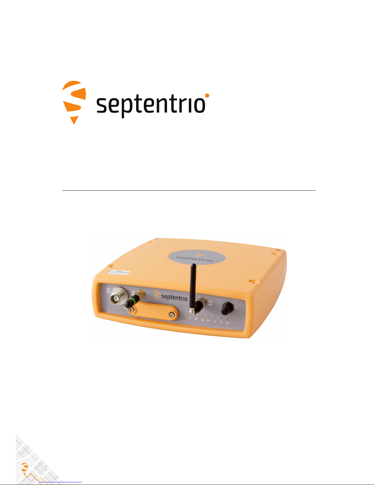
2 AsteRx-U overview
The AsteRx-U provides multi-frequency, multi-constellation GNSS capability together with
GNSS Heading, L-Band positioning and wireless communications within a rugged IP67
housing for the broadest range of applications. Use any smartphone, tablet or computer to
operate the AsteRx-U without any special configuration software via the built-in webserver
accessible via Wi-Fi, Ethernet or USB connection.
2.1 AsteRx-U key features
• 544 channels for tracking all known and future signals from GPS, GLONASS, GALILEO,
BEIDOU, IRNSS, QZSS and SBAS on both antennas
• Precise and robust heading calculation
• cm-level (RTK) and sub dm-level (PPP) position accuracy
• Dual L-band channel, support for TERRASTAR corrections
• Septentrio GNSS+ algorithms for robust industrial performance
• Integrated cellular modem, Bluetooth, WIFI and optional UHF radio
2.1.1 GNSS
• 544 hardware channels for simultaneous tracking of all visible satellite signals
• Supported signals: GPS (L1, L2, L5), GLONASS (L1,L2,L3), GALILEO (E5ab, AltBoc, E6),
BEIDOU (B1, B2, B3), IRNSS (L5), QZSS (L1,L2,L5) (Galileo,
• Beidou and IRNSS, are optional features)
• All-in-view SBAS (EGNOS, WAAS, GAGAN, MSAS, SDCM) (incl. L5 tracking)
• Integrated dual channel L-band receiver
• 100 Hz Raw data output (code, carrier, navigation data) (optional feature)
• 20 Hz SBAS, DGNSS, PPP and RTK (50 Hz available in future firmware upgrade)
• A Posteriori Multipath Estimator Technique (APME+), including code and phase
multipath mitigation
• AIM+/WIMU interference mitigation unit, including chirp jammers (optional feature)
• ION+ Advanced scintillation mitigation
• L-Band reception robust against INMARSAT uplink interference (AsteRx-U MARINE
variant only)
• RAIM
• Differential GNSS (base station and rover)
• Real Time Kinematic (base and rover) (optional features)
• TERRASTAR and VERIPOS services (optional feature)
• Moving base positioning (optional feature)
• 8 GB Internal Memory
7

2.1. ASTERX-U KEY FEATURES
GNSS positioning accuracy
Horizontal Vertical
Standalone 1.2 m 1.9 m
SBAS 0.6 m 0.8 m
DGPS 0.4 m 0.9 m
TERRASTAR-D 6 cm < 10 cm
APEX 6 cm < 10 cm
ULTRA 6 cm < 10 cm
RTK performance
Horizontal accuracy 0.6 cm + 0.5 ppm
Vertical accuracy 1 cm + 1 ppm
Average time to fi 7 s
Velocity accuracy
Horizontal Vertical
0.01 m/s 0.015 m/s
Attitude accuracy
antenna separation Heading Pitch\Roll
1 m 0.1 0.2
10 m 0.01 0.02
Connectivity
• 3 hi-speed serial ports (RS232)
• Ethernet port (TCP/IP and UDP)
• Full speed USB (host and device)
• 2 Event markers
• xPPS output (max. 100 Hz)
• Integrated Bluetooth (2.1 + EDR/4.0)
• Integrated Quadband Cellular Modem (EDGE, 2G, 3G, 3.5G)
• Integrated Wi-Fi (802.11 b/g/n)
• Integrated UHF (406-470 MHz) (AsteRx-U UHF and MARINE variants only)
• Connector for separate L-Band antenna (AsteRx-U MARINE variant only)
8

2.2. ASTERX-U VARIANTS
2.2 AsteRx-U variants
The AsteRx-U is available in three variants:
Variant Main features
(Part number)
AsteRx-U
(410121)
• Integrated cellular modem
• Integrated Wi-Fi modem
• Integrated Bluetooth modem
AsteRx-U UHF
(410119)
• Integrated cellular modem
• Integrated Wi-Fi modem
• Integrated Bluetooth modem
• Integrated UHF radio with front-panel connector
AsteRx-U MARINE
(410120)
• Integrated cellular modem
• Integrated Wi-Fi modem
• Integrated Bluetooth modem
• Integrated UHF radio with front-panel connector
• Rear-panel connector for dedicated L-Band antenna
• L-Band reception robust against INMARSAT uplink
interference
9
2.3. ASTERX-U DESIGN
2.3 AsteRx-U design
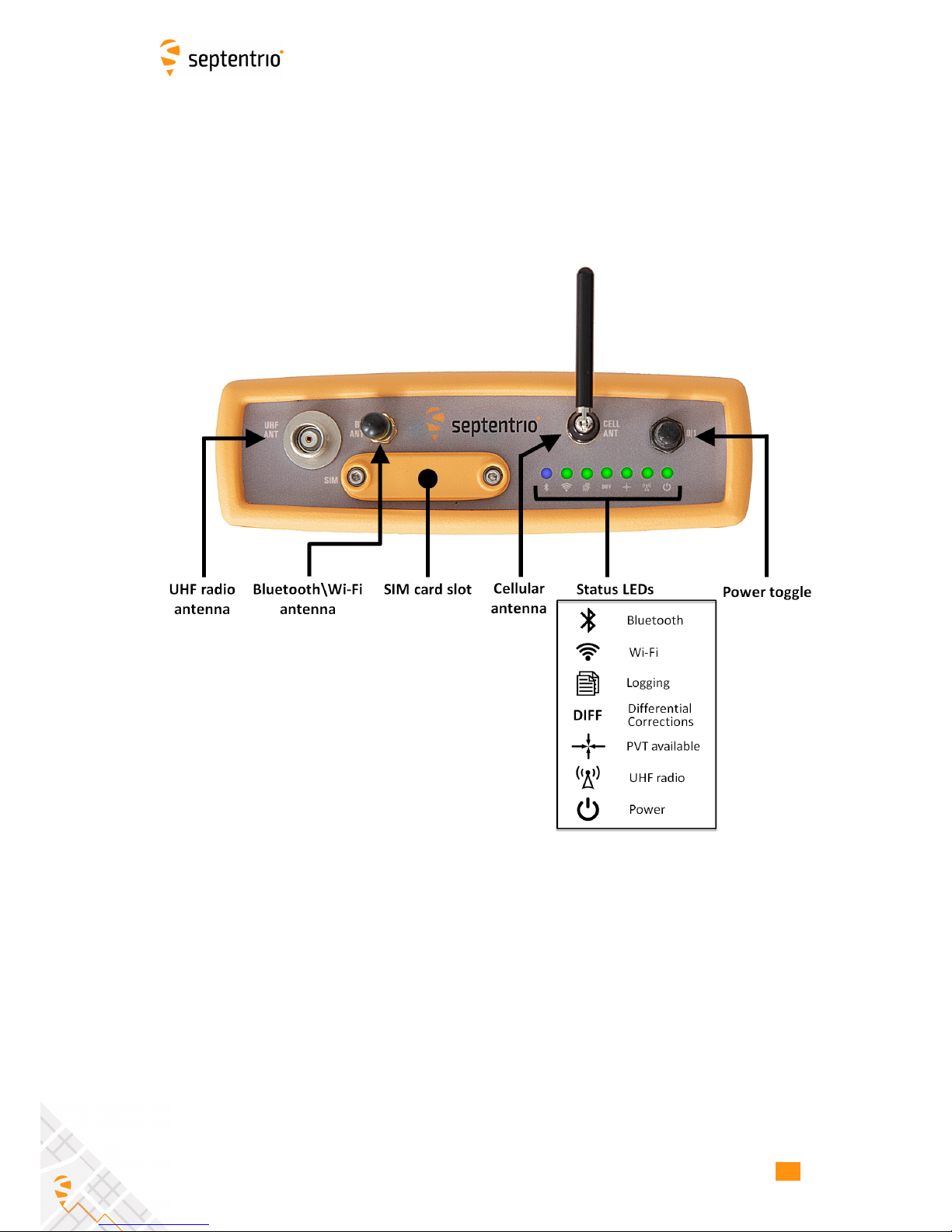
2.3.1 Front panel
The front-panel layout of the AsteRx-U with attached Bluetooth/Wi-Fi and Cellular antennas
is shown in Figure 2-1.
Figure 2-1: AsteRx-U front-panel layout
10

2.3. ASTERX-U DESIGN
2.3.2 LED description
LED Icon Behaviour
blue
Off: Bluetooth disabled
On: Bluetooth connected
Blinking slowly: Not connected but discoverable
green
Off: Wi-Fi disabled
On: Access-point mode or client mode
Blinking slowly: Establishing a connection in client mode
Blinking quickly: Error, not connected
green
Off: Not logging
On: Logging active, disk is mounted
Blinking slowly: Logging active, disk-space is low
Blinking quickly: Disk is full or not mounted
green
Off: No reception of corrections data
Blinking: Blinks on reception correction data
green
Off: PVT available
On: No PVT available
green
Off: UHF radio modem disabled
On: UHF radio modem in search mode
Blinking slowly: Data package sent/received
Blinking quickly: UHF radio modem in set-up mode
green
Off: Receiver is powered on
On: Receiver is powered off
11
2.3. ASTERX-U DESIGN
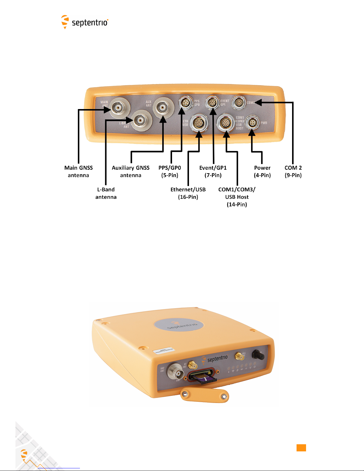
2.3.3 Rear panel
Figure 2-2 shows the layout of the rear-panel connectors on the AsteRx-U. The PIN
assigments for each socket can be found in the Appendix.
Figure 2-2: AsteRx-U rear-panel layout
2.3.4 SIM card slot
The SIM card can be inserted into the slot in the front panel of the AsteRx-U as shown in
Figure 2-3.
Important: Only insert or remove the SIM card while the unit is powered down.
Figure 2-3: SIM card slot on AsteRx-U
12
2.3. ASTERX-U DESIGN
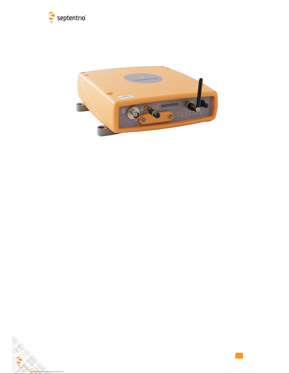
2.3.5 Mounting brackets
The AsteRx-U is supplied with mounting brackets which can be fitted to the unit as shown in
Figure 2-4.
Figure 2-4: Mounting brackets fitted to AsteRx-U
2.3.6 Internal memory
The AsteRx-U has an 8 GB Memory for internal data logging. Data can be logged in SBF or
NMEA format and may be retrieved via the logging tab of the web interface.
13
2.4. SHIPPING CASE CONTENTS
2.4 Shipping case contents
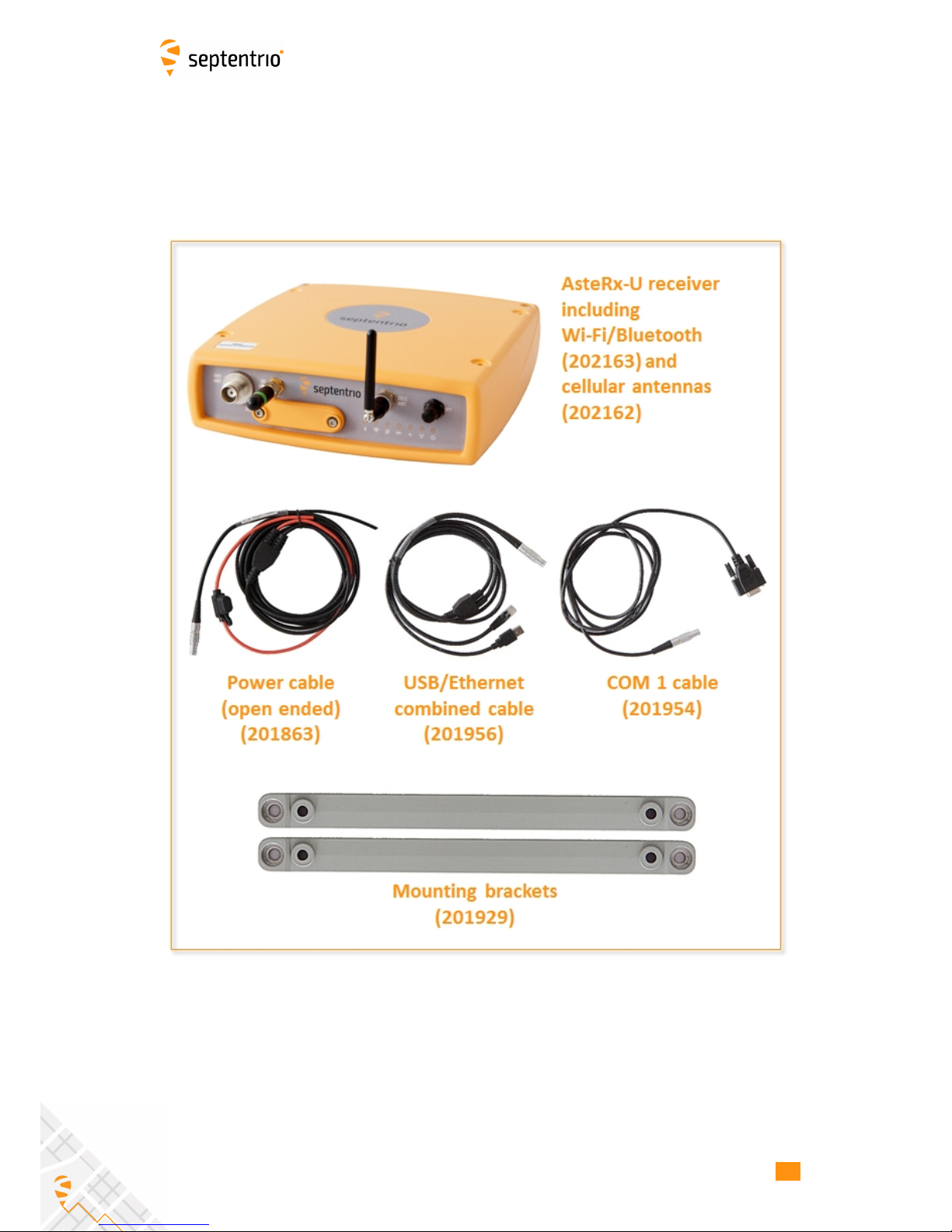
2.4.1 Supplied as standard
The following items with their part numbers are supplied as standard with the AsteRx-U.
14
2.4. SHIPPING CASE CONTENTS
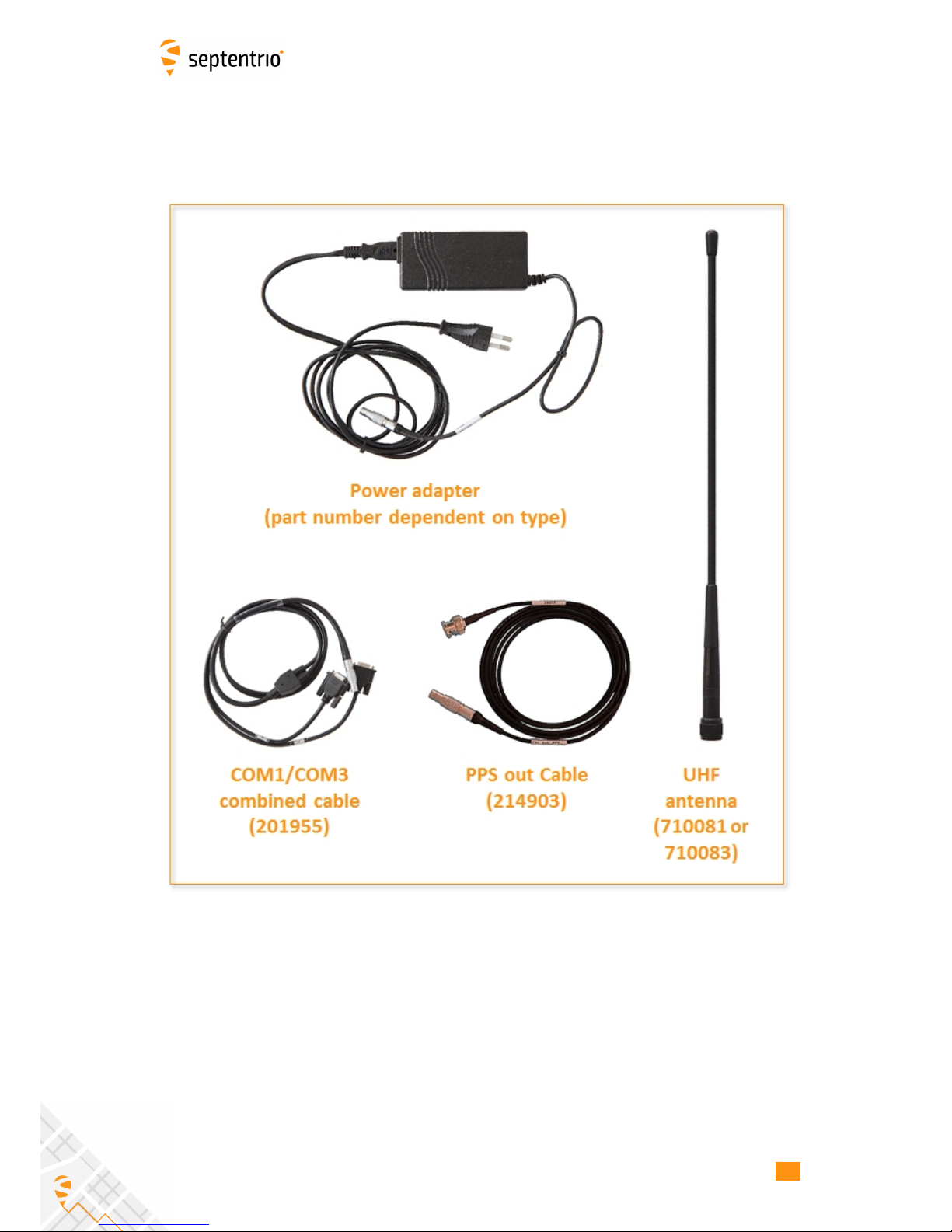
2.4.2 Optional items
The following items with their part numbers can be optionally purchased for use with the
AsteRx-U.
15

3 Quick start
This section details how to power-up, connect to and communicate with the AsteRx-U. The
AsteRx-U has an on-board web interface which the user can connect to in three ways:
Ethernet, USB or Wi-Fi. The AsteRx-U is fully configurable using the web interface. Please
note that older versions of certain browsers may not display properly on the web interface.
3.1 Powering the AsteRx-U
Using the supplied open-ended power cable, the receiver can be powered by applying 6
to 36 V via the power-in wire. The receiver can also be powered using the power adapter
(optionally available). The power socket is indicated in Figure 3-1.
Figure 3-1: Rear panel power socket
There is a power button on the front panel as shown in Figure 3-2 which you may also have
to press. If the AsteRx-U loses power while the power button is on, then it will automatically
boot up when power is restored.
Figure 3-2: Front panel power button
When the unit is powered initially, the front-panel LEDs will will follow a boot sequence
pattern.
16
3.2. CONNECTING AN ANTENNA
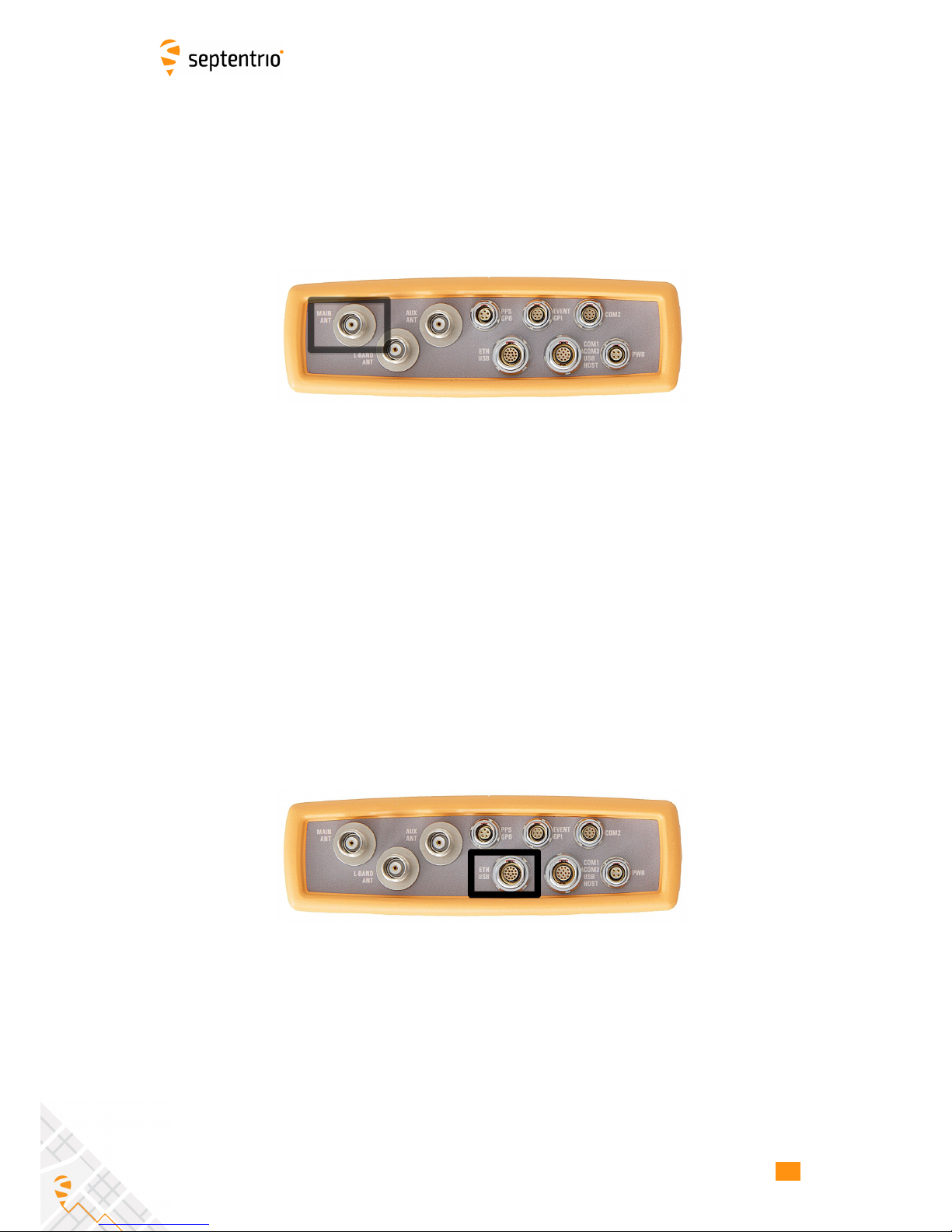
3.2 Connecting an antenna
The rear panel of the AsteRx-U has two TNC connectors for GNSS antennas: one for the main
antenna and one for an auxiliary antenna for heading applications. The AsteRx-U MARINE
has an additional, TNC connector for a dedicated L-Band antenna. To get started, connect
an antenna via an antenna cable to the main antenna connector of the AsteRx-U indicated
in Figure 3-3.
Figure 3-3: Rear-panel main antenna connector
3.3 Connecting to the AsteRx-U via the Web
Interface
You can connect to the receiver on any device that supports a web browser using the
receiver’s on board Web Interface. The connection can be made using either USB, Ethernet
or Wi-Fi. The following sections describe each of the connection methods.
3.3.1 Using the USB cable
Connect the combined USB/Ethernet cable to the connector labelled ’ETH USB’ on the rear
panel of the AsteRx-U and indicated in Figure 3-4.
Figure 3-4: Rear panel USB and Ethernet socket
The first time that the USB cable is connected to a device, you may be prompted to allow
installation of drivers which can take several minutes. When the drivers have been installed,
it is recommended to unplug then re-plug in the USB cable on your device to fully activate
the drivers.
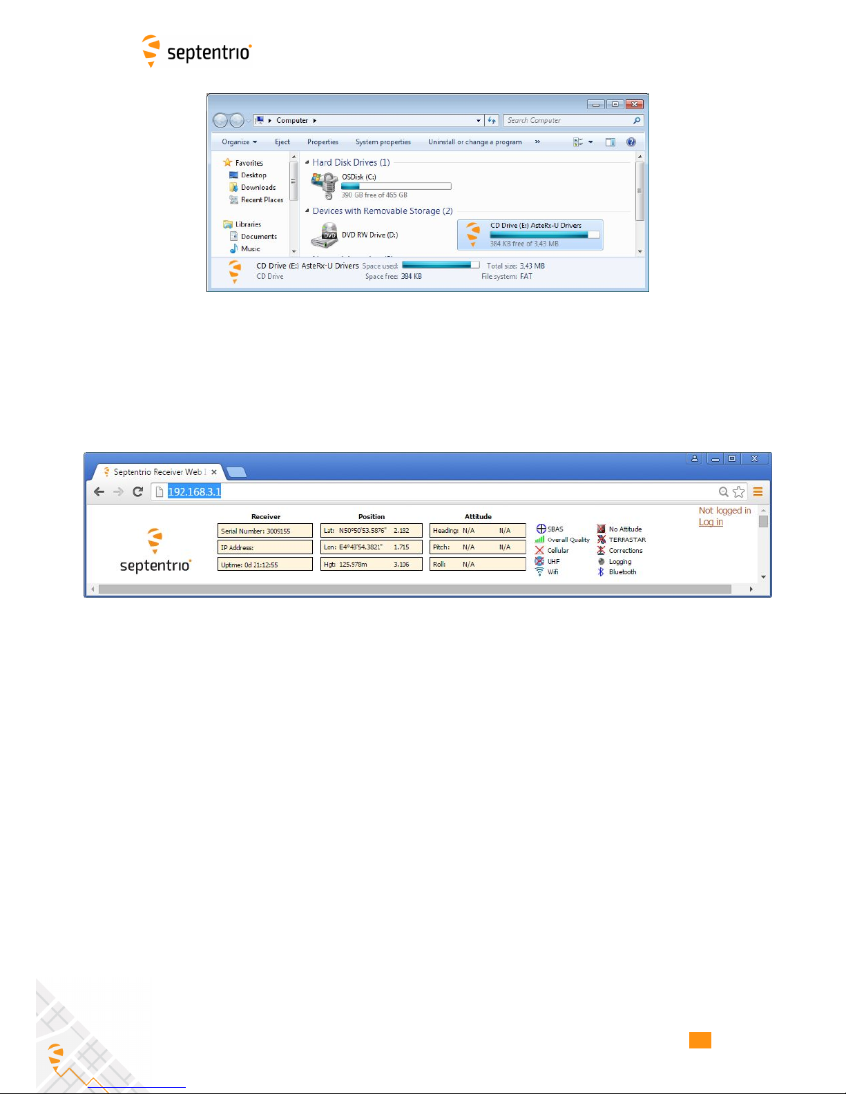
When the drivers have been correctly installed, the USB connection will appear as a
removable storage device as shown in Figure 3-5.
17
3.3. CONNECTING TO THE ASTERX-U VIA THE WEB INTERFACE
Figure 3-5: Screenshot showing USB connection after driver installation
The USB connection on the AsteRx-U functions as network adapter and the DHCP server
running on the receiver will always assign the AsteRx-U the IP address 192.168.3.1.
To connect to the AsteRx-U, you can then simply open a web browser using the IP address
192.168.3.1 as shown in Figure 3-6.
Figure 3-6: Connect to the Web Interface of the AsteRx-U over USB using the IP
address 192.168.3.1 on any web browser
18
3.3. CONNECTING TO THE ASTERX-U VIA THE WEB INTERFACE
3.3.2 Using the Ethernet cable
Step 1: Connect the combined USB/Ethernet cable
Connect the combined USB/Ethernet cable shown in Section 2.4.1 to the connector labelled
‘ETH USB‘ on the rear panel of the AsteRx-U indicated in Figure 3-7.
Figure 3-7: Rear panel USB and Ethernet socket
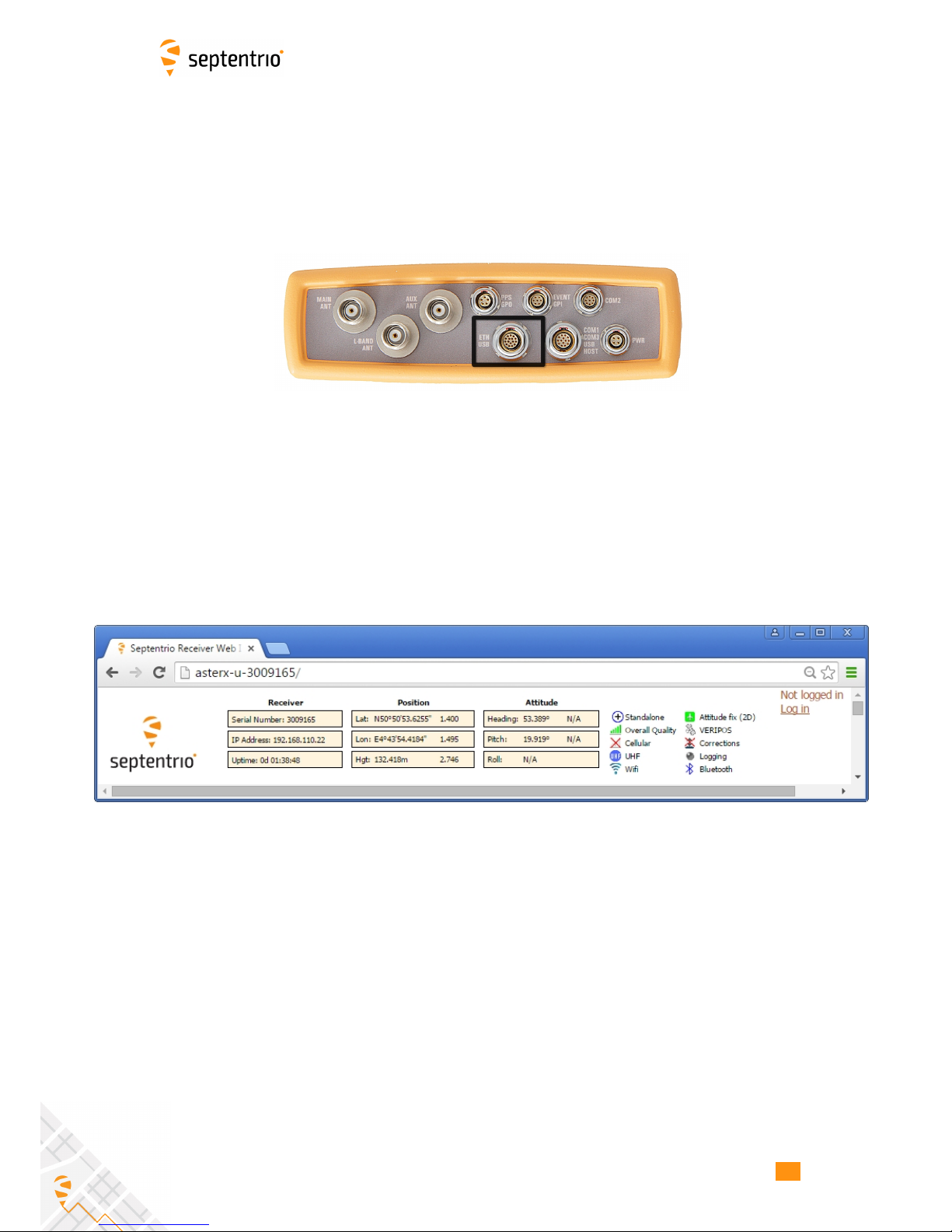
Step 2: Open a web browser and connect to the AsteRx-U
By default, the AsteRx-U has a DHCP address ‘http://Asterx-U-xxxxxxx’, where xxxxxxx are
the 7 digits of the AsteRx-U serial number. The serial number can be found on a sticker on
the corner of the outer casing of the receiver. Figure 3-8 shows a screenshot of an Ethernet
connection to a receiver with serial number 3009165 using ‘http://asterx-u-3009165’.
Figure 3-8: Connecting to the Web Interface via Ethernet
19
3.3. CONNECTING TO THE ASTERX-U VIA THE WEB INTERFACE
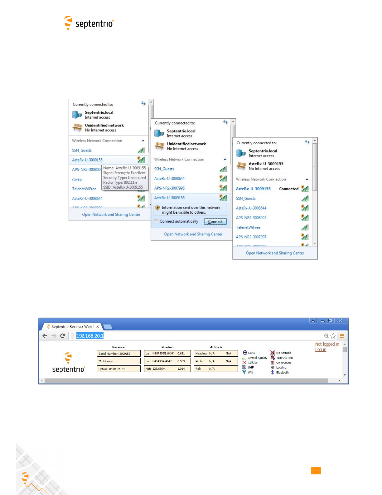
3.3.3 Over Wi-Fi
The Web Interface can also be accessed over a Wi-Fi connection. On your PC or tablet,
search for visible Wi-Fi signals: the AsteRx-U identifies itself as a wireless access point named
’AsteRx-U-serial number’. The serial number of the AsteRx-U can be found on an identification
sticker on the receiver housing. Select and connect to the AsteRx-U as shown in Figure 3-9.
Figure 3-9: Select the AsteRx-U from the list of detected wireless signals and
connect
When your PC is connected to the AsteRx-U Wi-Fi signal, you can open a web browser using
the IP address: 192.168.20.1 as shown in Figure 3-10.
Figure 3-10: Connect to the Web Interface of the AsteRx-U over Wi-Fi using the IP
address 192.168.20.1 on any web browser
20
3.4. HOW TO CONFIGURE SBF AND NMEA OUTPUT
3.4 How to configure SBF and NMEA output
The AsteRx-U can output position and GNSS data in both standard NMEA format and
Septentrio’s proprietary compact binary format SBF. This following sections detail how to
configure connections to other devices in order to send data.
3.4.1 Output over a serial COM connection
The AsteRx-U can be connected via a serial COM cable to an RS-232 compatible secondary
device.
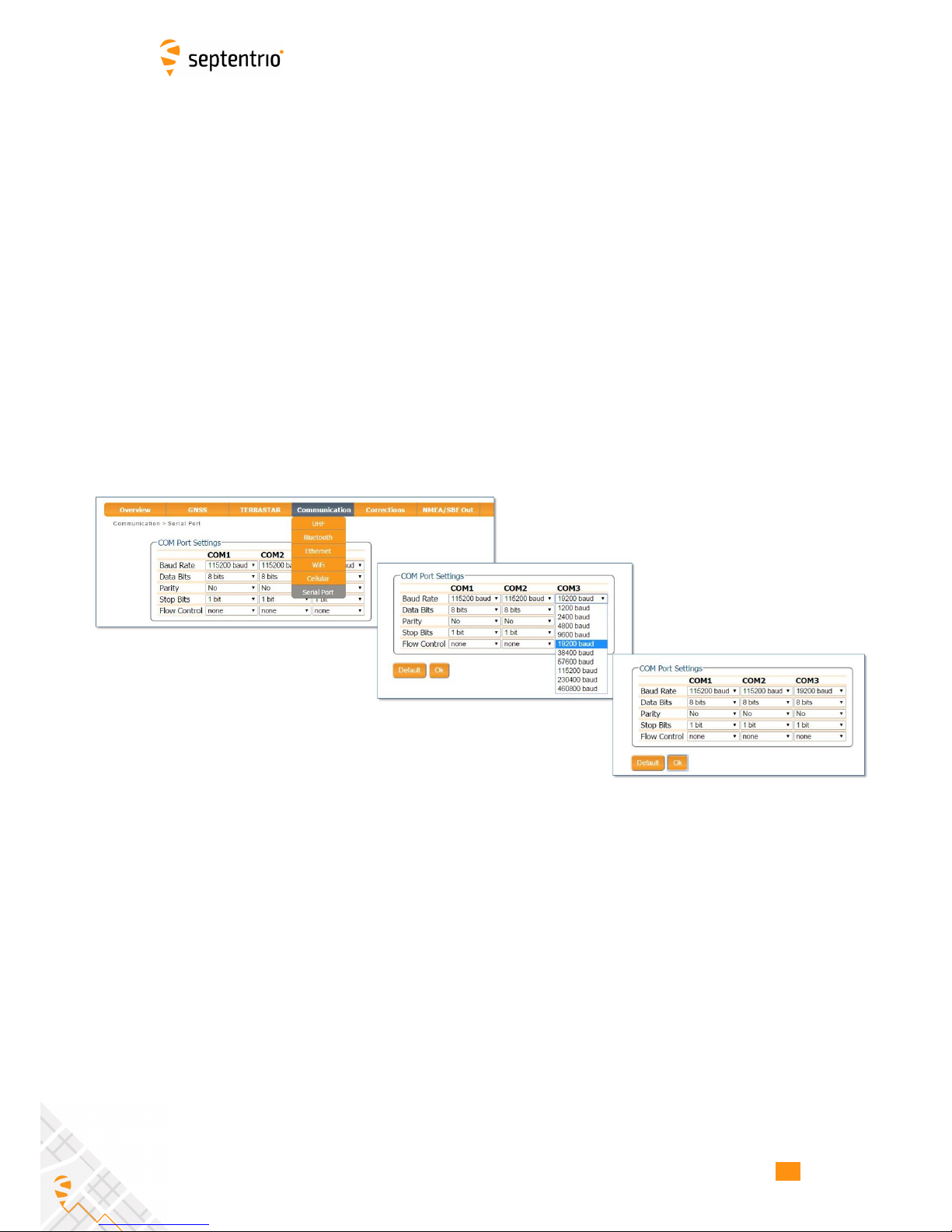
Step 1: Configure the serial COM port
The COM port of the AsteRx-U should be configured with the same baud rate and flow control
setting of the coupled device. These settings can be configured via the ‘Communication’ tab
as shown in Figure 3-11. In this example, COM3 is set with a speed of 19200 baud.
Figure 3-11: Configure the baud rate and flow control of the AsteRx-U
21
 Loading...