

Page 1
Doc. No.: D10053.EN Rev.: 14 Page 1 of 29
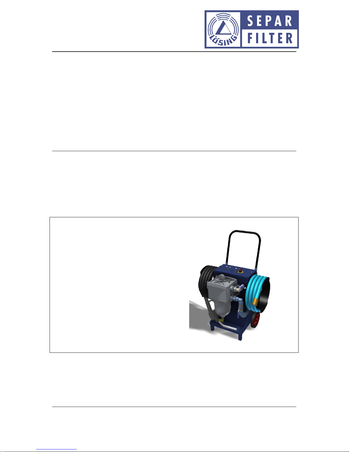
Operating instructions: SWK-2000/40/WSA filter mobile
Willibrord Lösing
Filterproduktion GmbH
W. Lösing Filterproduktion GmbH • Am Walzwerk 2 • 45527 Hattingen
Operating manual
SWK-2000/40/WSA filter mobile
These operating instructions are valid for:
SWK-2000/40/WSA filter mobile
HW Version 0.9 and 1.0
SW Version 19.0
Article No.: 06 2386
Page 2

Doc. No.: D10053.EN Rev.: 14 Page 2 of 29
Operating instructions: SWK-2000/40/WSA filter mobile
Willibrord Lösing
Filterproduktion GmbH
W. Lösing Filterproduktion GmbH • Am Walzwerk 2 • 45527 Hattingen
Contents
1 References ............................................................................................................... 4
2 General .................................................................................................................... 5
3 Notes on safety ........................................................................................................ 5
3.1 Utilisation according to specification............................................................................................. 5
4 Scope of delivery ...................................................................................................... 6
5 Technical data .......................................................................................................... 8
5.1 Electrical specs. .............................................................................................................................. 8
5.1.1 Battery operation ........................................................................................................................... 8
5.1.2 Mains operation ............................................................................................................................. 8
5.2 Temperature range ........................................................................................................................ 8
5.3 Mechanical data ............................................................................................................................. 8
5.4 Weight and dimensions ................................................................................................................. 9
6 Transport grip ......................................................................................................... 10
7 Electrical connections ............................................................................................. 11
7.1 Mechanical connections .............................................................................................................. 11
8 Connection ............................................................................................................. 12
8.1 Network or battery connection cable dismantling ...................................................................... 13
9 Indications and operating elements ........................................................................ 14
10 Function ................................................................................................................. 15
10.1 Fuel filling nozzle .......................................................................................................................... 16
10.2 Pump and filter operation ........................................................................................................... 17
10.2.1 Timer function.............................................................................................................................. 19
10.2.2 Fault reports ................................................................................................................................. 20
10.3 Selection of the display-language ................................................................................................ 22
10.4 Automatic pump disconnection and dry-running monitoring ..................................................... 23
10.4.1 Selection of the automatic pump disconnection and the dry-running monitoring..................... 23
10.5 Water sensor ................................................................................................................................ 25
11 Notes on use .......................................................................................................... 26
11.1 Maintenance ................................................................................................................................ 26
11.1.1 Water drain .................................................................................................................................. 26
11.1.2 Filter change ................................................................................................................................ 26
Page 3

Doc. No.: D10053.EN Rev.: 14 Page 3 of 29
Operating instructions: SWK-2000/40/WSA filter mobile
Willibrord Lösing
Filterproduktion GmbH
W. Lösing Filterproduktion GmbH • Am Walzwerk 2 • 45527 Hattingen
11.1.3 Sensor technology........................................................................................................................ 26
11.2 Filter bowl cleaning ...................................................................................................................... 27
11.3 Water sensor cleaning ................................................................................................................. 27
12 Declaration of conformity ....................................................................................... 28
13 Index ...................................................................................................................... 29
Page 4

Doc. No.: D10053.EN Rev.: 14 Page 4 of 29
Operating instructions: SWK-2000/40/WSA filter mobile
Willibrord Lösing
Filterproduktion GmbH
W. Lösing Filterproduktion GmbH • Am Walzwerk 2 • 45527 Hattingen
1 References
[R1]
Type: Installation instructions
Title: Installation instruction SEPAR english.pdf
Page 5

Doc. No.: D10053.EN Rev.: 14 Page 5 of 29
Operating instructions: SWK-2000/40/WSA filter mobile
Willibrord Lösing
Filterproduktion GmbH
W. Lösing Filterproduktion GmbH • Am Walzwerk 2 • 45527 Hattingen
2 General
The filter mobile is subjected to a detailed final control check in the works. Therefore small
quantities of diesel oil can still be present in the device. These remaining quantities do not impair
either the storage or the function of the device.
3 Notes on safety
The two available connections for the supply voltage (Connection 1: Mains supply line for 115 V AC
or 230 V AC. Connection 2: Connection for 12 V DC battery operation) may not be used
simultaneously. Operation at any operating voltages other than listed in the technical data is not
permissible. Employment in explosion-hazard areas is not allowed. The maximum ambient
temperature for the operation of the filter mobile is 40°C. If the electrical cables should indicate
damage, switch off the filter mobile immediately using the emergency switch and disconnect from
the supply voltage (pull plug or with 12 V operation remove terminals from the battery). In case of
damage to the bus system and the filter, the filter mobile may also not be employed since otherwise
fuel can reach the environment.
The pump motor and the supply line can warm up considerably during operation. Touching these
parts is to be avoided to protect against burn injuries.
If the filter mobile is operated at ambient temperatures above 25°C, the operator interface can
warm up considerably!
In order to avoid the discharge of fuel residues, the fuel filling nozzle and the shut-off valve must be
closed after the use of the filter mobile.
3.1 Utilisation according to specification
Provide diesel oils and mineral oils with a dynamic viscosity < 10 mPas, a flash point > 55°C and a
boiling point > 160°C. The utilisation of liquids which can attack the filter casing (aluminium), the
pumps (steel), the plastic parts (polyamides) and the seals (NBR) is not planned, and can lead to
damage to the filter mobile or to dangerous operating states.
All work on the SWK-2000/40/WSA filter mobile must be implemented in voltage-free status.
Page 6
Doc. No.: D10053.EN Rev.: 14 Page 6 of 29
Operating instructions: SWK-2000/40/WSA filter mobile
Willibrord Lösing
Filterproduktion GmbH
W. Lösing Filterproduktion GmbH • Am Walzwerk 2 • 45527 Hattingen
4 Scope of delivery
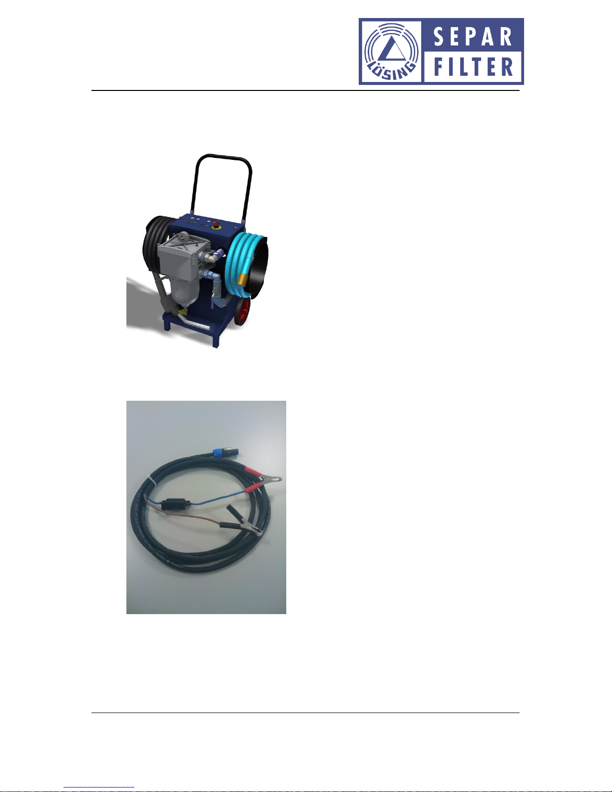
• SWK-2000/40/WSA filter mobile
• 12 V supply line with crocodile clips, plug connector, fuse holder and fuse protection
(50 A).
Page 7

Doc. No.: D10053.EN Rev.: 14 Page 7 of 29
Operating instructions: SWK-2000/40/WSA filter mobile
Willibrord Lösing
Filterproduktion GmbH
W. Lösing Filterproduktion GmbH • Am Walzwerk 2 • 45527 Hattingen
• 230 V supply line with plug incorporating grounding contact and PowerCon plug
connector
• Operating manual
Page 8

Doc. No.: D10053.EN Rev.: 14 Page 8 of 29
Operating instructions: SWK-2000/40/WSA filter mobile
Willibrord Lösing
Filterproduktion GmbH
W. Lösing Filterproduktion GmbH • Am Walzwerk 2 • 45527 Hattingen
5 Technical data
These operating instructions describe the module assembly in the following implementation:
Hardware version: 0.9 and 1.0
Software version: 19.0
5.1 Electrical specs.
5.1.1 Battery operation
Operating voltage: 12 V DC
Maximum operating voltage: 15 V DC
Maximum current consumption: 30 A
5.1.2 Mains operation
Operating voltage: 100 V AC to 240 V AC
Mains frequency: 50 Hz to 60 Hz
Maximum current consumption: 5 A (at 115 V AC)
5.2 Temperature range
Operating temperature: -40°C to 40°C
Storage temperature: -40°C to 80°C
5.3 Mechanical data
IP Protection Type: IP41
Maximum supply capacity of the pumps: approx. 40 l/min
Maximum net positive suction head: approx. 2 m
Page 9
Doc. No.: D10053.EN Rev.: 14 Page 9 of 29
Operating instructions: SWK-2000/40/WSA filter mobile
Willibrord Lösing
Filterproduktion GmbH
W. Lösing Filterproduktion GmbH • Am Walzwerk 2 • 45527 Hattingen
5.4 Weight and dimensions
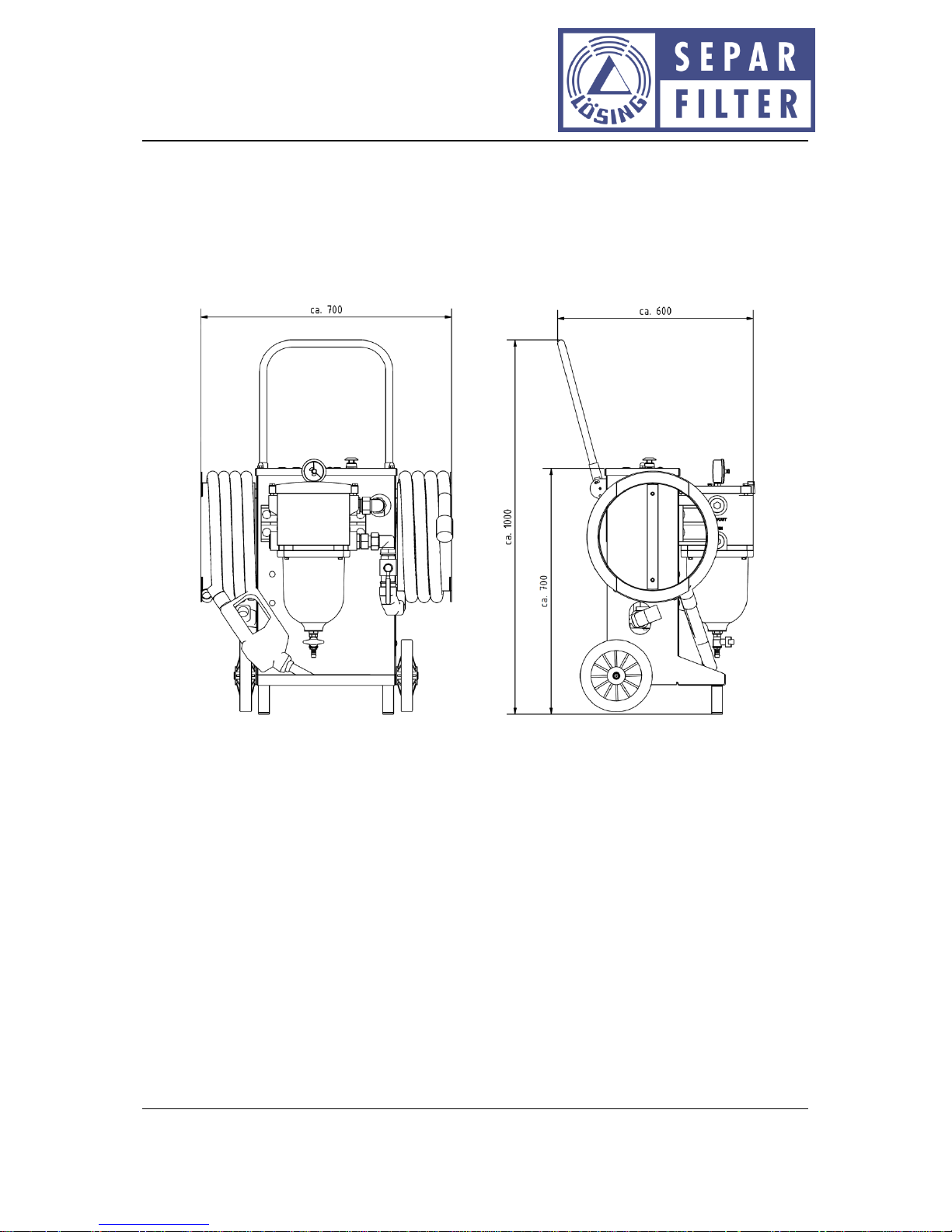
Dead weight (without fuel): 65 kg
The dimensions (tolerances < 5 mm) can be taken from the following drawing.
Page 10
Doc. No.: D10053.EN Rev.: 14 Page 10 of 29
Operating instructions: SWK-2000/40/WSA filter mobile
Willibrord Lösing
Filterproduktion GmbH
W. Lösing Filterproduktion GmbH • Am Walzwerk 2 • 45527 Hattingen
6 Transport grip
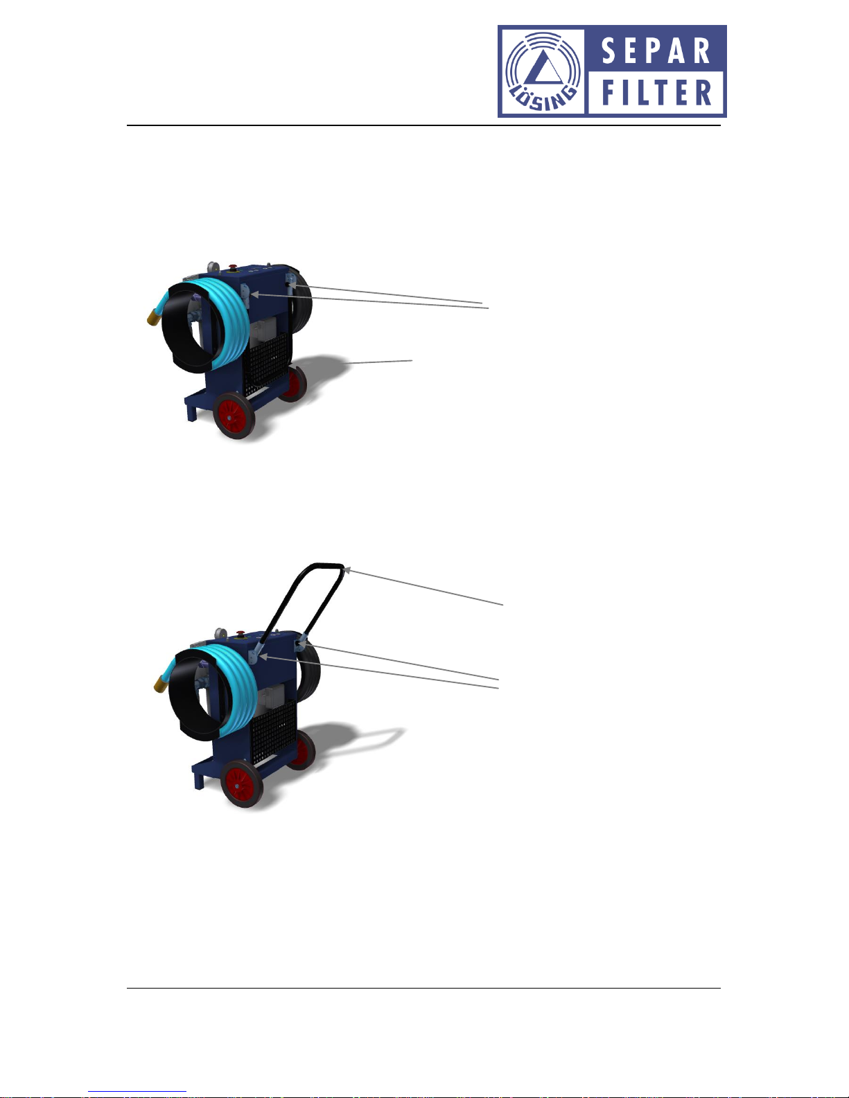
The filter mobile is equipped with a hinged transport grip. The transport grip can be fixed in three
settings. In the folded-in status (lowest position) the total height is approx. 750 mm.
For transport, the grip is lifted upwards (maximum height approx. 1000 mm). For that, the two
knurled screws must be loosened anti-clockwise so far until the transport grip can be pivoted
upwards. Pivot the transport grip up until the knurled screws can be turned into one of the upper
two bores. Tighten both knurled screws clockwise hand-tight for the fixing of the transport grip.
Folded-in transport grip
Knurled screws (one per side)
Opened-out transport grip
Knurled screws (one per side)
Page 11
Doc. No.: D10053.EN Rev.: 14 Page 11 of 29
Operating instructions: SWK-2000/40/WSA filter mobile
Willibrord Lösing
Filterproduktion GmbH
W. Lösing Filterproduktion GmbH • Am Walzwerk 2 • 45527 Hattingen
7 Electrical connections
The SWK-2000/40/WSA filter mobile is provided with two connections for supply voltages:
Connection 1: Plug connector for mains cables with plug incorporating grounding contact,
operating voltage 115 V AC to 230 V AC (removable)
Connection 2: Plug connector for cables with crocodile clips (battery operation), operating
voltage 12 V DC (removable)
The SWK-2000/40/WSA filter mobile is protected against incorrect polarity of the operating voltage
(12 V DC). However, any operation in case of pole-inversal of supply voltage is not possible.
The SWK-2000/40/WSA filter mobile is supplied as standard with plug incorporating grounding
contact. Operation with other mains power connections is also possible with separately available
adapter cables, as long as the electrical connected loads are maintained. The supply line for battery
operation is included in the scope of delivery. Further design implementations on request.
7.1 Mechanical connections
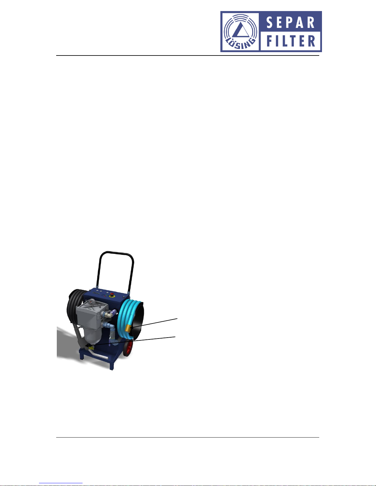
The SWK-2000/40/WSA filter mobile is provided with two fuel lines. The fuel suction pipe is
equipped filter-sided with a shut-off valve and at its end with a check valve, and the output line is
equipped with a fuel filling nozzle,
Check valve
Fuel filling nozzle
Page 12
Doc. No.: D10053.EN Rev.: 14 Page 12 of 29
Operating instructions: SWK-2000/40/WSA filter mobile
Willibrord Lösing
Filterproduktion GmbH
W. Lösing Filterproduktion GmbH • Am Walzwerk 2 • 45527 Hattingen
8 Connection
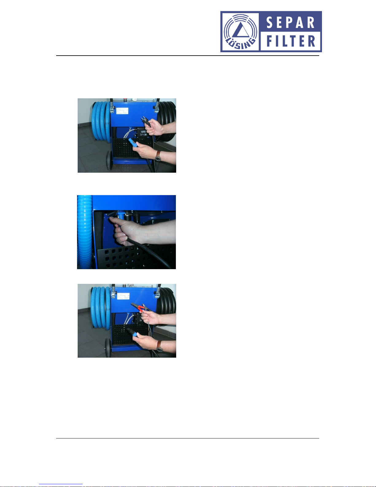
The SWK-2000/40/WSA filter mobile is connected with a suitable voltage supply.
Mains connection via delivered power cable (115 V AC; 230 V AC):
Insert power cable into the blue socket on the filter mobile and rotate clockwise until
engagement:
Battery connection using delivered battery lead (12 V DC):
Page 13
Doc. No.: D10053.EN Rev.: 14 Page 13 of 29
Operating instructions: SWK-2000/40/WSA filter mobile
Willibrord Lösing
Filterproduktion GmbH
W. Lösing Filterproduktion GmbH • Am Walzwerk 2 • 45527 Hattingen
Insert battery leads into black socket on the filter mobile and rotate clockwise until
engagement:
Clamp crocodile clips onto the battery. The red clamp onto the positive terminal and the
black clamp onto the minus pole. In case of batteries which are switched in series, it is to be
ensured that the crocodile clips are connected to only one battery (12 V).
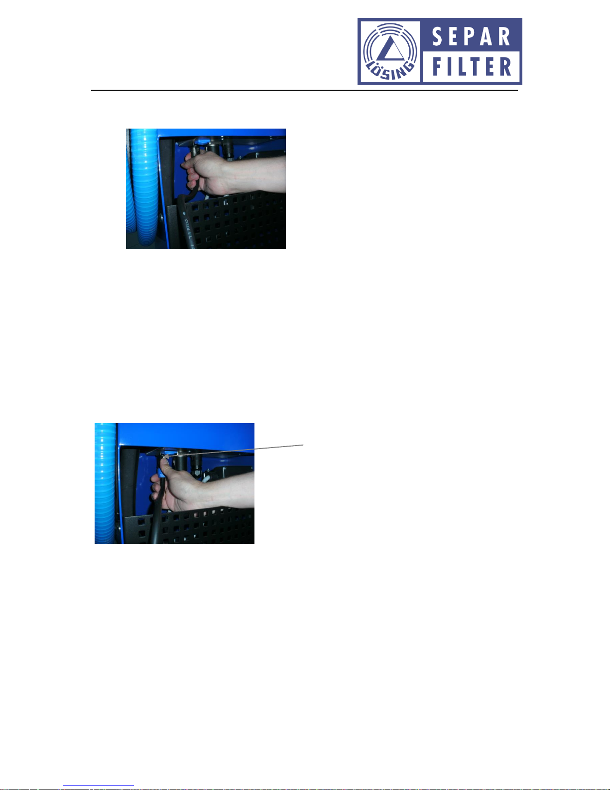
8.1 Network or battery connection cable dismantling
Both the plug connector of the power cable and the plug connector of the battery lead are equipped
with a mechanical interlocking.
For the dismantling of the network or battery connection cable, pull the interlocking of the plug
connector on the filter mobile with the thumbs downward and rotate plug connectors anti-clockwise
up to the stop. After that, the plug connector can be pulled simply from the socket.
Interlocking
Page 14
Doc. No.: D10053.EN Rev.: 14 Page 14 of 29
Operating instructions: SWK-2000/40/WSA filter mobile
Willibrord Lösing
Filterproduktion GmbH
W. Lösing Filterproduktion GmbH • Am Walzwerk 2 • 45527 Hattingen
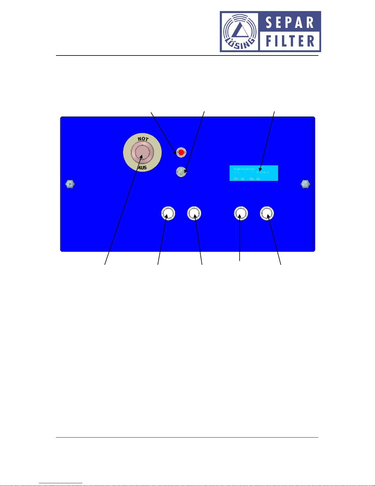
9 Indications and operating elements
For the operation of the SWK-2000/40/WSA filter mobile two buttons, an emergency switch, two
indication LED's, one display, one pressure indication and a shut-off valve are available.
Illustration 1: Indications and operating elements
Error
Power
- Timer +
- Motor +
Error indication
Ready to operate
Display
Emergency Off switch
Timer “-”
Timer “+”
“-”; slower
“+”; faster
Page 15
Doc. No.: D10053.EN Rev.: 14 Page 15 of 29
Operating instructions: SWK-2000/40/WSA filter mobile
Willibrord Lösing
Filterproduktion GmbH
W. Lösing Filterproduktion GmbH • Am Walzwerk 2 • 45527 Hattingen
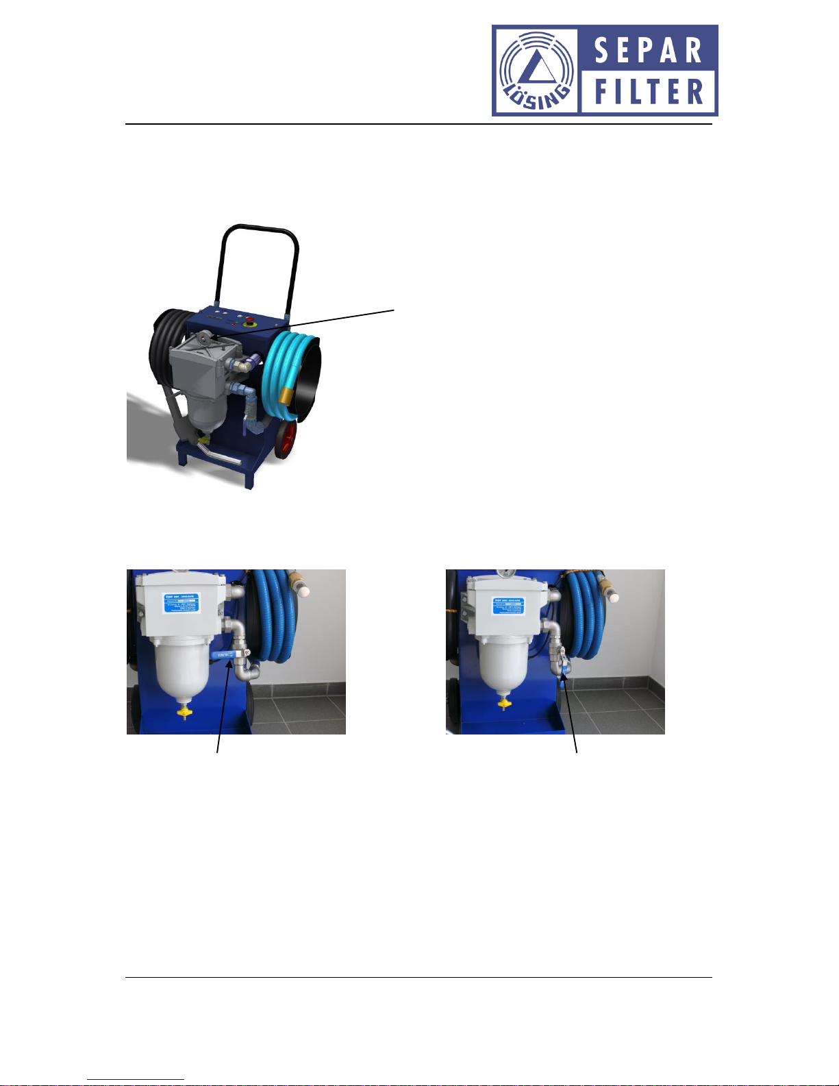
The SWK-2000/40/WSA filter mobile is equipped with a pressure indication. A dirt accumulation of
the filter element can be identified in good time using this instrument by the pressure decrease in
the filter system. This pressure indication is located in the cover of the filter casing.
10 Function
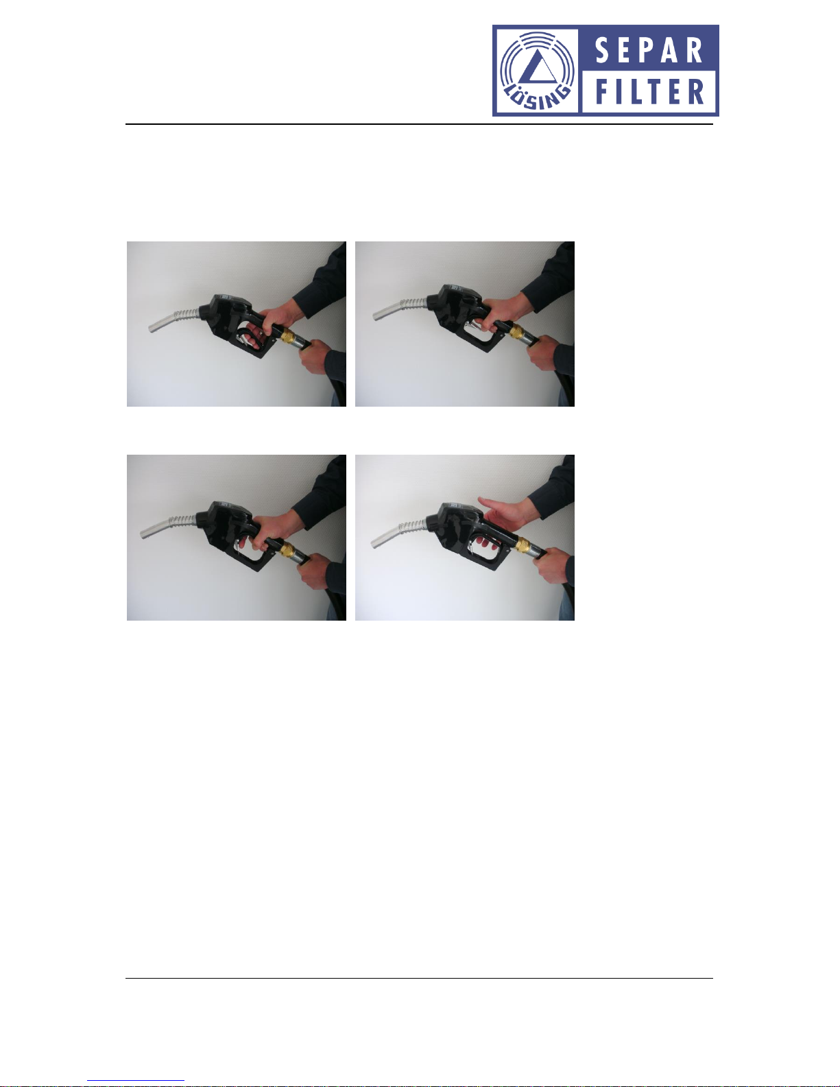
Attention! Before operational start-up of the pumps, the shut-off valve is to be opened.
Pressure
Shut-off valve
closed
Shut-off valve
opened
Page 16
Doc. No.: D10053.EN Rev.: 14 Page 16 of 29
Operating instructions: SWK-2000/40/WSA filter mobile
Willibrord Lösing
Filterproduktion GmbH
W. Lösing Filterproduktion GmbH • Am Walzwerk 2 • 45527 Hattingen
10.1 Fuel filling nozzle
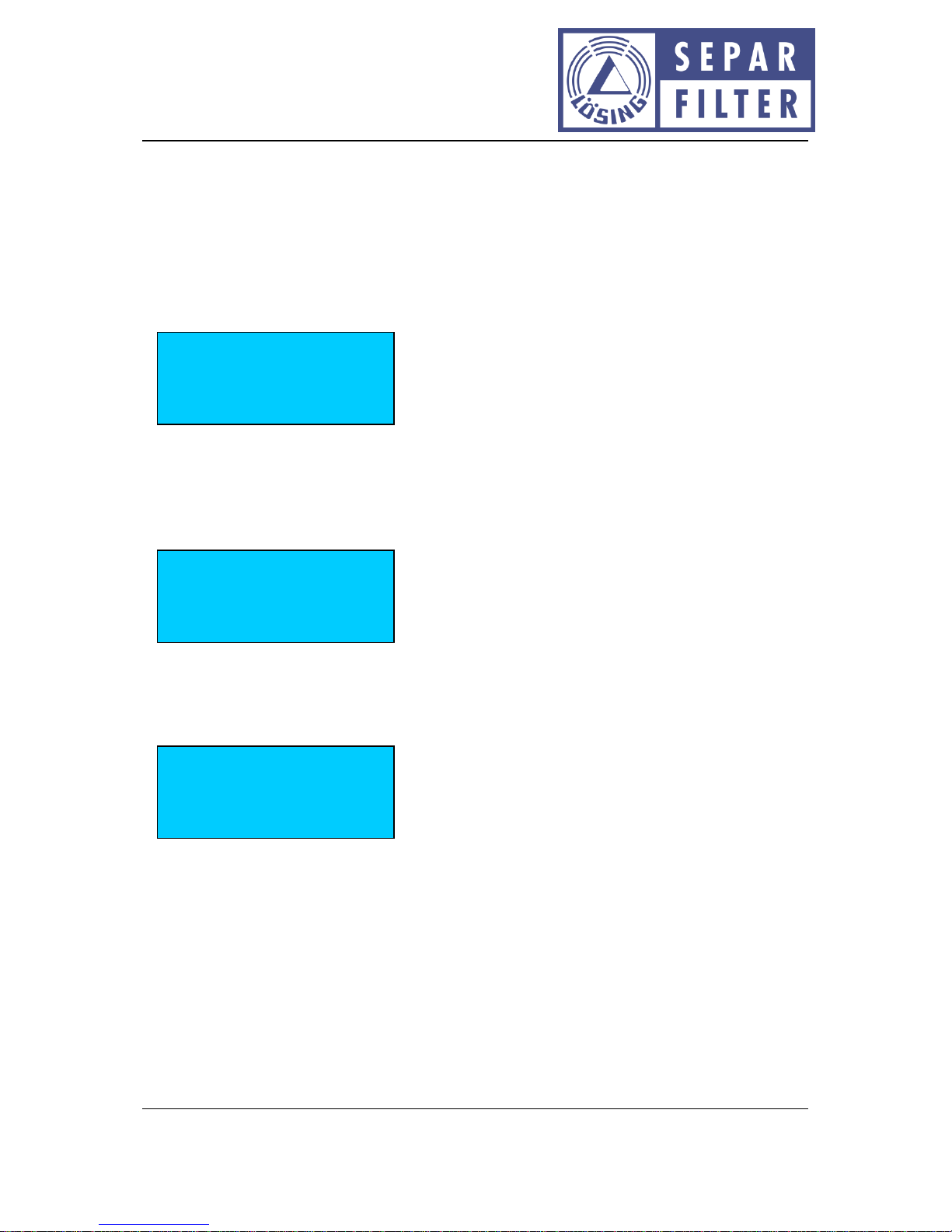
The fuel filling nozzle is equipped with a latching mechanism. In the engaged status, the fuel filling
nozzle is open. As soon as the fuel filling nozzle dips into the fuel during pump operation, the
interlocking is released and the fuel filling nozzle closed.
Push tapping lever of the gun
Engage interlocking lever. Fuel filling nozzle is now open.
Page 17
Doc. No.: D10053.EN Rev.: 14 Page 17 of 29
Operating instructions: SWK-2000/40/WSA filter mobile
Willibrord Lösing
Filterproduktion GmbH
W. Lösing Filterproduktion GmbH • Am Walzwerk 2 • 45527 Hattingen
10.2 Pump and filter operation
After connection to the supply voltage, the operating voltage is switched on by acknowledgement of
the emergency switch (pull switch button upwards).
The green operation indication (LED) and the display light up. After the initialisation (initialisation
signals always in German), the following switch-on signal is indicated on the display for approx. 2
seconds:
The version numbers, the serial number and the date of manufacture can also be other numerical
values, according to implementation.
After that, the selected operating modes are displayed for approx. two seconds:
You can find an explanation of the operating mode in Chapter 10.4.
After successful self-test, the display indicates:
The ”-” character in the second line at the left edge indicates the function of the left key and the ”+”
character in the second line at the right edge indicates the function of the right key. Dependent on
the font of the display employed, the characters can vary slightly at the left and right line edge. In
the lower line is displayed the temperature status of the electronics and pump motor. In this case
”TE: OK” means: the temperature of the electronics is within the planned range, and ”TM: OK”
means: the temperature of the pump motor is within the planned range. Before beginning the pump
and filter operation, the shut-off valve and the fuel filling nozzle are to be opened.
The filter mobile is now ready for operation.
Pump operation mode
Automatic
Dry-running monitor.
manually
Pump flow rate
- < > ~ 0 l/m +
TE: OK TM: OK
Lösing – Filtermobil
HW-V 1.0
SW-V 13.0
SNr.:000099-18.06.14
Page 18
Doc. No.: D10053.EN Rev.: 14 Page 18 of 29
Operating instructions: SWK-2000/40/WSA filter mobile
Willibrord Lösing
Filterproduktion GmbH
W. Lösing Filterproduktion GmbH • Am Walzwerk 2 • 45527 Hattingen
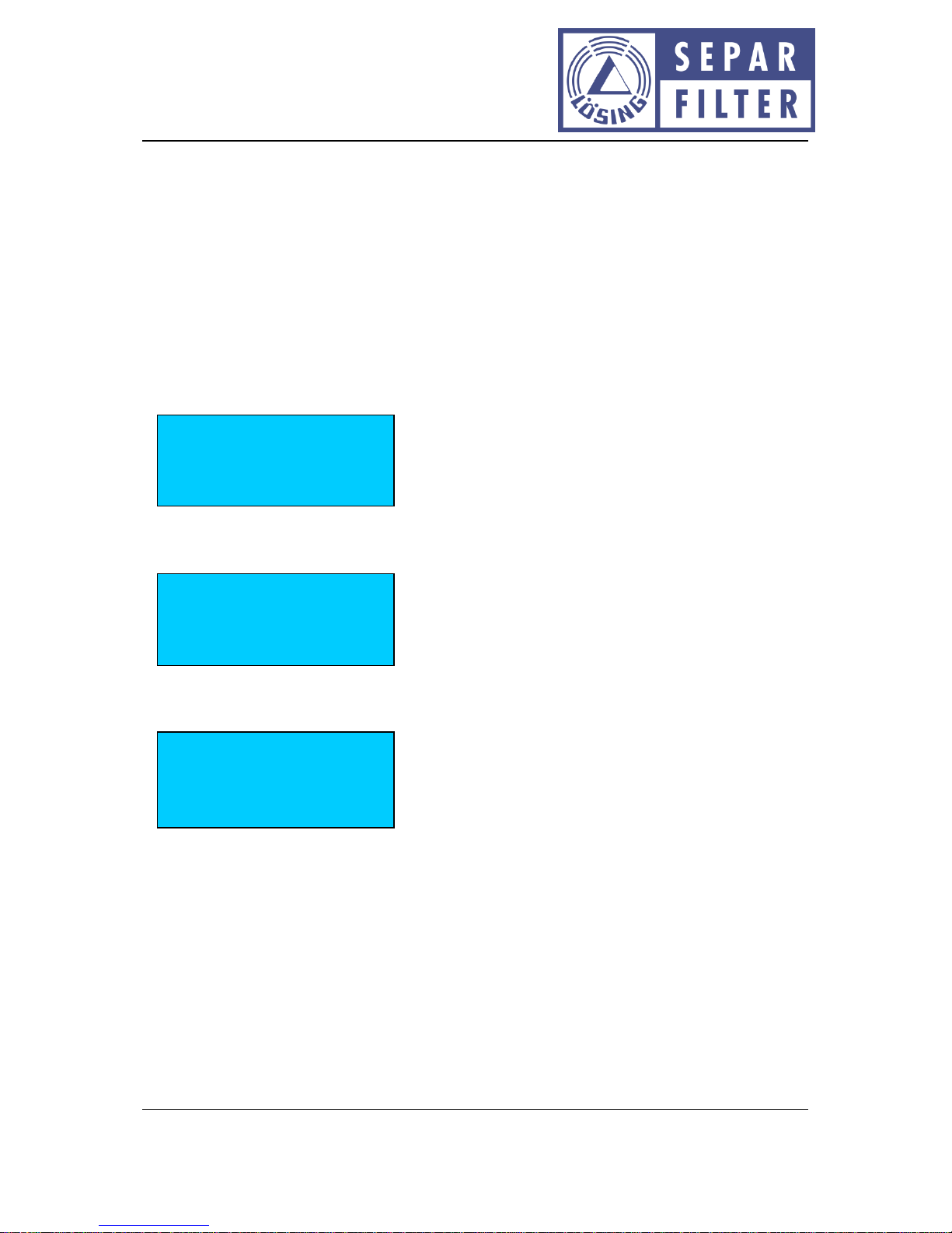
For the start of the fuel pump, the right-hand key ”+” must be pressed shortly. The pump ramps
slowly up to a supply capacity of approx. 15 l/min. Smaller flow rates cannot be adjusted. If the key
”+” is pressed longer, the supply capacity of the pump can be increased to approx. 40 l/min. The
instantaneous supply capacity can be read off in the display behind the brackets in l/min. The actual
supply capacity depends on many external influences, and can therefore deviate from the indicated
supply capacity. An actuation of the key ” – ” reduces the supply capacity. With an indication of 15
l/min, an actuation of the key ” – ” results in the disconnection of the pump. If both keys are pressed
simultaneously, the pump is also switched off. For the duration of the key activation, the key
function is displayed between the brackets.
Key ”+” activated:
Key ”-” activated:
Key ”+” and key ” – ” activated:
An actuation of the emergency switch (press down forcefully in the direction of front panel) ends all
pumping procedures and the electrics and electronics disconnect from the supply voltage.
Pump flow rate
- < + > ~ 24 l/m +
TE: OK TM: OK
Pump flow rate
- < - > ~ 22 l/m +
TE: OK TM: OK
Pump flow rate
- < + > ~ 24 l/m +
TE: OK TM: OK
Page 19
Doc. No.: D10053.EN Rev.: 14 Page 19 of 29
Operating instructions: SWK-2000/40/WSA filter mobile
Willibrord Lösing
Filterproduktion GmbH
W. Lösing Filterproduktion GmbH • Am Walzwerk 2 • 45527 Hattingen
10.2.1 Timer function
The filter mobile is equipped with a timer function, with which allows the pump to be operated for a
preselected time. The pumping procedure is ended automatically after this time.
10.2.1.1 Adjusting the required runtime
The runtime can be adjusted in intervals of 15 minutes, up to a maximum of 2 hours. In order to
initiate this setting-adjustment process, the key ”Timer +” must be pressed with pump operation
switched off. In the display, the following indication appears:
A minimum runtime of 15 minutes is already preset. As a result of actuation the keys ”Timer +” and
”Timer –”, the required runtime can be adjusted. If the keys ”Timer +” and ”Timer –” are activated
simultaneously, the procedure is interrupted and the control returns to the basic status. When the
timing has ended, this setting menu can be exited with the key ”+; faster”.
With the keys ”+; faster” and ”-; slower”, the required pumping capacity can be adjusted as
described in Chapter 8.2. The residual runtime of the pumps is updated continuously in the display.
After this time the pump switches off automatically and the filter mobile returns to the basic status.
Every time-controlled pump operation is implemented only once.
10.2.1.2 Timer operation interruption
The simultaneous actuation of the keys ”+; faster” and ”-; slower” or the actuation of the Emergency
Off switch interrupt the timer operation and end the pumping procedure. The filter mobile returns to
the basic status.
Pump flow rate
- < - > ~ 0 l/m +
Time left: 00:15:00
TE: OK TM: OK
timer adjustment:
runtime: 00:15:00
Page 20
Doc. No.: D10053.EN Rev.: 14 Page 20 of 29
Operating instructions: SWK-2000/40/WSA filter mobile
Willibrord Lösing
Filterproduktion GmbH
W. Lösing Filterproduktion GmbH • Am Walzwerk 2 • 45527 Hattingen
10.2.2 Fault reports
If the operation indication does not light up with proper connection of the supply voltage and after
the reset-acknowledging of the emergency switch, there is an internal defect. In this case, the repair
must be implemented by the manufacturer.
10.2.2.1 Operating voltage too high
If, in battery operation, a voltage of more than 15 V is connected by mistake (e.g. 24 V through series
switching of two 12 V batteries), a fault report appears in the display:
The fault report is deleted by connection of the correct operating voltage and a new start.
10.2.2.2 Operating voltage too low
If, in battery operation, a voltage of less than 10 V is connected by mistake (e.g. 6 V battery, as in
very old vehicles), a fault report appears in the display:
The fault report is deleted by connection of the correct operating voltage.
A T T E N T I O N
Failure: < 10 V!
A T T E N T I O N
Failure: > 12 V!
Page 21
Doc. No.: D10053.EN Rev.: 14 Page 21 of 29
Operating instructions: SWK-2000/40/WSA filter mobile
Willibrord Lösing
Filterproduktion GmbH
W. Lösing Filterproduktion GmbH • Am Walzwerk 2 • 45527 Hattingen
10.2.2.3 Temperature of the pump too high
For the protection of the pumps, the filter mobile is equipped with an automatic temperature and
load-dependent pump control. To avoid pump temperatures which are too high, this regulation
reduces the power consumption of the pumps as appropriate. As soon as this regulation intervenes
in the pump control, this status is indicated by ”!”.
If, during operation, the motor temperature of the pump exceeds the permissible limit value in spite
of regulation, the pump is switched off and the following signal appears in the display:
The pump can be switched on again only when the pump motor has cooled down.
10.2.2.4 Too high temperature of the electronic control
If, during operation, the temperature of the electronics exceeds the permissible limit value, the
pump is also switched off and the following signal appears in the display:
The pump can be switched on again only when the electronics has cooled down.
An excessive amount heat with the pump or electronics can have various reasons; amongst those are
too high ambient temperature and a too high viscosity of the pumped and filtered media.
Pump flow rate
- < - >! ~ 29 l/m +
TE: OK TM: OK
A T T E N T I O N
Electronic too hot
A T T E N T I O N
Drive too hot
Page 22
Doc. No.: D10053.EN Rev.: 14 Page 22 of 29
Operating instructions: SWK-2000/40/WSA filter mobile
Willibrord Lösing
Filterproduktion GmbH
W. Lösing Filterproduktion GmbH • Am Walzwerk 2 • 45527 Hattingen
10.3 Selection of the display-language
The signals in the display can be displayed in 8 different languages. In order to select the required
language, the filter mobile is connected to the supply voltage and the emergency switch activated. If
the keys ”+” and ”–” are activated simultaneously during switch-on procedure (unlocking of the
emergency switch), the menu for the selection of the required language is accessed.
The character ”<” behind the respective language shows the currently selected language. With the
key ”–” a change can be made between the different languages. The character ”<” then skips to the
next possible language. With the key ”+” the language is selected, behind which the character ”<” is
displayed momentarily. If e.g. German is selected, as can be seen in the above illustration, in the
display there appears the signal:
If e.g. Polish is selected, there appears:
The language selected in each case is stored and retained for the following operation, also when the
filter mobile is switched off and on again.
After the language selection, the filter mobile changes into standard operation, as described in the
previous sections.
Jezyk:
Polski
Sprache:
Deutsch
Deutsch <English
Nederlands Francais
Espanol Polski
Türkce Italiano
Page 23
Doc. No.: D10053.EN Rev.: 14 Page 23 of 29
Operating instructions: SWK-2000/40/WSA filter mobile
Willibrord Lösing
Filterproduktion GmbH
W. Lösing Filterproduktion GmbH • Am Walzwerk 2 • 45527 Hattingen
10.4 Automatic pump disconnection and dry-running monitoring
The filter mobile is equipped with an automatic disconnection of the pump motor. As soon as the
fuel filling nozzle dips into the fuel with on-going pumping, the fuel filling nozzle closes automatically.
So that the fuel pump does not continue to remain in this operating state unnecessarily, the
electronic control switches the pump off approx. 2 seconds after the fuel filling nozzle was closed.
Under certain circumstances (e.g. large net positive suction heads, low temperatures or operation
with highly viscous fuels) faulty disconnections of the pump motor can result. For such cases, the
automatic pump switch-off can be disabled.
The dry-running monitoring switches off the pumps if no fuel has been suctioned for longer than 5
minutes. For a secure function, the shut-off valve and the fuel filling nozzle must be open.
Under certain circumstances this function can also lead to faulty disconnections (e.g. if the fuel
indicates a very low viscosity). For such cases, the dry-running monitoring can also be disabled. If
the automatic pump disconnection or the dry-running monitoring, or both functions, have been
switched off, the operator is responsible for the manual disconnection to avoid damage.
10.4.1 Selection of the automatic pump disconnection and the dry-running
monitoring
The operating mode of the pump can be changed from automatic disconnection to manual
disconnection. In order to select the required operating mode, the filter mobile is connected to the
supply voltage and the emergency switch activated. If the timer keys ”+” and ” – ” (in this case the
two left-hand keys) are activated simultaneously during the switch-on procedure, the menu is
accessed for the selection of the required operating mode. In the display, the following signal
appears:
The timer keys “+” and “-” can now be released. With the keys “+” and “-” (in this case the two righthand keys), the operating mode can be selected.
Pump operation mode
<+> automatic
<-> manually
Page 24
Doc. No.: D10053.EN Rev.: 14 Page 24 of 29
Operating instructions: SWK-2000/40/WSA filter mobile
Willibrord Lösing
Filterproduktion GmbH
W. Lösing Filterproduktion GmbH • Am Walzwerk 2 • 45527 Hattingen
The key “+” selects the automatic operating mode, with which the pump motor is switched off
automatically after the closing of the tap. In the display the signal appears:
The key “-” selects the manual operation, with which the pump motor can be switched on and off
manually only. In the display the signal appears:
Directly after this signal, the selection menu for the dry-running monitoring appears.
With the keys “+” and “-” (in this case the two right-hand keys) the dry-running monitoring can be
switched on and off. The key “+” selects the automatic operating mode, with which the pump motor
is switched off after approx. 5 minutes in case of dry running. In the display the signal appears:
The key “-” selects the manual operating mode, with which the pump motor must be switched off
manually in case of dry running. In the display the signal appears:
Dry-running monitor
manually
Dry-running monitor
automatic
Dry-running monitor
<+> automatic
<-> manually
Pump operation mode
manually
Pump operation mode
automatic
Page 25
Doc. No.: D10053.EN Rev.: 14 Page 25 of 29
Operating instructions: SWK-2000/40/WSA filter mobile
Willibrord Lösing
Filterproduktion GmbH
W. Lösing Filterproduktion GmbH • Am Walzwerk 2 • 45527 Hattingen
10.5 Water sensor
After switching on the operating voltage, the water indication, independent of the medium in which
the sensor surfaces are located, does not display any water. About 1 second later, the measurement
procedure starts. The water sensor implements the necessary measurements over more than two
surfaces in the medium to be examined.
After the assessment, the result is output over the display and the red LED. The indication is
implemented in all cases delayed, in order to avoid a flickering of the indication in case of fluctuating
medium.
Normal operation: The sensor is flushed with fuel. The red LED remains dark. In the display,
no signal is output.
Water in the fuel: The sensor is flushed with water. The pump is switched off. The red LED
lights up and the following signal is output in the display:
This signal remains present until the shutdown of the operating voltage,
even when no more water flushes the sensor. The filter mobile can be
put into operation again only when the water has been removed from
the bowl, as described in Chapter 11.1.1.
Faults in the sensor: The red LED changes into flashing mode. In the display the signal ”Too
much water” appears in the same rhythm. After removal of the fault, red
LED and the display again indicate the result of the measurement.
A T T E N T I O N
too much water
Page 26

Doc. No.: D10053.EN Rev.: 14 Page 26 of 29
Operating instructions: SWK-2000/40/WSA filter mobile
Willibrord Lösing
Filterproduktion GmbH
W. Lösing Filterproduktion GmbH • Am Walzwerk 2 • 45527 Hattingen
11 Notes on use
The SWK-2000/40/WSA filter mobile may not be employed in case of damage to the filter casing, the
supply lines and the electrical cables. In this case, repair is necessary with the manufacturer.
The water sensor may not be employed with damaged measurement tip. For better identification of
damage, the measurement tip is painted green. Scratches or paint-free surfaces indicate damage to
the sensor and require the replacement of the affected sensor.
11.1 Maintenance
Before all maintenance work the filter mobile is to be disconnected from the supply voltage, the
shut-off valve is to be closed and both fuel lines may not be immersed in liquids.
11.1.1 Water drain
If the filter bowl is filled with water up to the installation level of the water sensor, this filling level is
reported over the water indication (red LED on the front panel of the filter mobile). The collected
water must be drained off now at the latest.
For a precise description of the procedural method, see:
" Installation instruction SEPAR english.pdf"
11.1.2 Filter change
According to dirt accumulation, the filter element must be changed at regular intervals. Before the
change, any water and dirt which are still present in the filter system must be drained off via the
drain valve into a suitable container.
For a precise description of the procedural method, see:
" Installation instruction SEPAR english.pdf"
11.1.3 Sensor technology
The water sensor is wear-free and maintenance-free. However, it must be ensured that the sensor
surfaces indicate no contamination or damage in order to obtain unambiguous results of
measurement. If the sensor should indicate any damage, the sensor must be replaced. Repair is not
possible.
11.1.3.1 Dismantling and installation of sensor
Before the sensor removal, the filter is to be emptied completely (see Chapter Filter change). The
sensor is bonded in, however, it can easily be removed from the filter bowl with a matching openend wrench. The removed sensor can now be examined for dirt accumulation and damage. If no fault
is detectable, the sensor can be re-installed after cleaning of the sensor and filter bowl (see Chapter
11.2 and 11.311.3).
Page 27

Doc. No.: D10053.EN Rev.: 14 Page 27 of 29
Operating instructions: SWK-2000/40/WSA filter mobile
Willibrord Lösing
Filterproduktion GmbH
W. Lösing Filterproduktion GmbH • Am Walzwerk 2 • 45527 Hattingen
The removed sensor is sealed with the enclosed O-ring. The screw thread of the water sensor is
coated with a suitable, non-alcoholic and soluble bolt-securing agent (e.g. Delo-ML 5298) and
secured against falling out by this. The sensor thus prepared is screwed hand-tight into the filter
bowl. The restart of operation may not be implemented until after the complete drying of the boltsecuring agent. The mandatory drying time depends on the employed bolt-securing agent and is to
be looked up in the relevant data sheets.
11.2 Filter bowl cleaning
Only clean diesel oil should be employed for the cleaning of the filter bowl.
For a precise description of the procedural method, see:
" Installation instruction SEPAR english.pdf"
11.3 Water sensor cleaning
After removal, the water sensor can be cleaned with a soft cloth. In the case of fixed-adhering
contamination, a non-alcoholic, standard household cleaner may be applied with the cleaning cloth.
The cleaning agent must be completely removed after that. The water sensor may not be employed
until after complete drying, as described in Chapter 11.1.3.1.
The employment of sharp cleaning tools or sharp and peaked objects can lead to damage to the
sensor surfaces and therefore must be avoided.
Page 28
Doc. No.: D10053.EN Rev.: 14 Page 28 of 29
Operating instructions: SWK-2000/40/WSA filter mobile
Willibrord Lösing
Filterproduktion GmbH
W. Lösing Filterproduktion GmbH • Am Walzwerk 2 • 45527 Hattingen
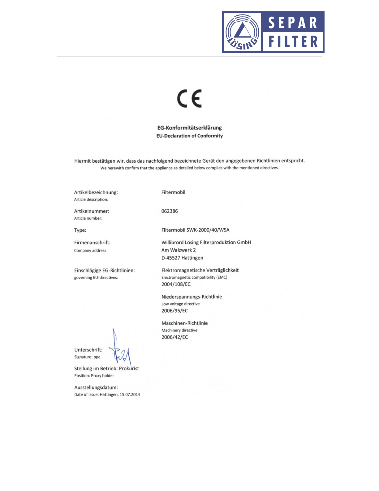
12 Declaration of conformity
Page 29

Doc. No.: D10053.EN Rev.: 14 Page 29 of 29
Operating instructions: SWK-2000/40/WSA filter mobile
Willibrord Lösing
Filterproduktion GmbH
W. Lösing Filterproduktion GmbH • Am Walzwerk 2 • 45527 Hattingen
13 Index
Automatic pump disconnection 23
Bolt-securing agent 27
Cleaning agent 27
Display 14
Dry running monitoring 23
Emergency switch 14
Hardware version 8
Language selection 22
Measurement tip 26
Motor temperature 21
Notes on use 25
Operating voltage 8
Sensor surface 25
Shut-off valve 14
Software version 8
 Loading...