

Page 1
INSTRUCTION MANUAL
http://www.separel.com
SEPAREL
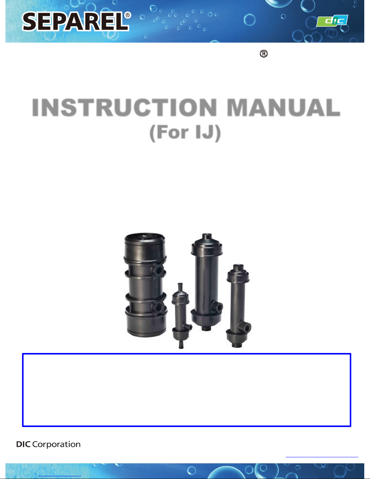
EF ‘External Flow’ Small Size Series
・EF-MICRO
・EF-G2 Series
・EF-G3 Series
・EF-G5 Series
Before using the SEPAREL® EF small size series, be sure to read this instruction manual
to ensure safe andproper use.
DIC will not have any liability to a customer or end user in connection with any costs and
damages arising directly or indirectly from any defective modules.
We are not responsible for any usage, installation, or any other handling done by the
customer. The module must be used, installed, and handled responsibly by the customer.
(For IJ)
Hollow Fiber Membrane Module
Ver. 1. 5
June 3, 2016
Application Materials Product Division
Page 2
■ About this Instruction M anual
This instruction manual explains how to handle SEPAREL® EF small size
degassing modules, such as the EF-MICRO, EF-G2, EF-G3, and EF-G5 series,
with precautions to be followed for your safety.
Before using the SEP AREL® EF small size series, be sure to read this
instruction manual to ensure safe and proper use.
Depending on use conditions, proper methods for usage and storage may differ
even though there are descriptions about usage methods, storage methods, and
risks associated with the product module within this manual.
Please note that this manual does not describe all information about risks
related to usage and storage of the product.
Although the content of this instruction manual is based on reliable testing and
measurement results, no guarantees are provided for its accuracy.
DIC does not have any responsibility for anything described or not described in
this manual.
The details of this instruction manual may be modified for improved reliability of
the SEPAREL® EF series or to account for changes in its design.
2
2
Application Materials Product Division
INSTRUCTION MANUAL
Page 3
3
3
Application Materials Product Division
INSTRUCTION MANUAL
■Warranty, Warranty Period
【Warranty】
At the time of delivery, DIC warrants that the Separel module will be free from defects in material and
workmanship and meet the specifications supplied to the customer by DIC.
【 Warranty Period 】
The following Warranty Period is applied only if customer use of the Separel module is in accordance with the
instructions contained in this manual, the specification sheet, any applicable Cleaning Guides and the Warranty
Statement.
(1) Water
Maximum 12 months from the date of delivery of the module
- This warranty period is applied only if customer refers to P.11, 3-3 (1).
- The above warranty will be voided in the event that water of unspecified quality is used.
(2) Liquids other than water
- Water-Based Liquid : Maximum 12 months from the date of delivery of the module*1
- Non-Water-Based Liquid : Maximum 6 months from the date of delivery of the module*1
*1 The warranty periods shown above are strictly to demonstrate the maximum warranty period available for
the
modules. Any actual warranty period will be based upon the results of compatibility tests of the module
with
all liquids which may come in contact with the module. The compatibility testing procedures will be
informed
to the customer by DIC. It is the customer’s responsibility to conduct the compatibility tests and
provide
the results thereof to DIC. In accordance with the results of the compatibility test, any warranty period
will
be determined through consultations between DIC and the customer. DIC and the customer will agree in
writing
to the warranty period, as well as, terms of use for the module (“Warranty Statement”).
If a liquid other than water (2) is used, only several SEPAREL products are applicable—please refer to Table 1
below.
Page 4
■ Regarding Reproduction and Photocopying of this Manual
◆ Reproduction of thi s manual in whole or in part is strictly prohibited.
◆ The content of this manual are subject to change without notice.
◆ SEPAREL® is a registered trademark of the DIC Corporation.
4
4
Application Materials Product Division
INSTRUCTION MANUAL
【Warranty Remedy】
During the applicable warranty period as specified in the Warranty Statement, any defective
module will be replaced free of charge by DIC in cases where a defect is found under normal
use in accordance with this instruction manual and under use and storage conditions
specified in the specification sheet and Warranty Statement.
This is the sole remedy available to the customer under this warranty. DIC will not have any
liability to a customer or end user in connection with any costs and damages arising
directly or indirectly from any defective modules.
We are not responsible for any usage, installation, or any other handling done by the
customer. The module must be used, installed, and handled responsibly by the customer.
The above warranty will be voided in the event that a liquid which has not been
specified for use between the customer and DIC, as specified in the Warranty
Statement, is used in the module or by any other use, installation or handling that is
not in accordance with the instructions contained in this manual, the specification
sheet and Warranty Statement.
This module is consumable. DIC recommends that customers replace the module
within the warranty period.
Page 5
5
Contents
1. General Precautions P. 5
2. Upon Receipt P. 5
3. Installation P. 5
4. Start-Up P. 9
5. Shutoff and Storage P. 10
6. Restart P. 11
7. Maintenance P. 11
Reference Data
1. Basic Principles of Degassing P.11
2. Vacuum Pressure Degree P.12
3. Setting Value of Vacuum Pressure Degree P.13
4. Range of Liquid Flow Rate P.14
5. Inner Volume P.15
6. Trouble shooting P.16
Contacts P.17
5
Application Materials Product Division
INSTRUCTION MANUAL
Page 6
1. BASIC PRECAUTIONS
2. UPON RECEIPT
6
6
1-1. Maintain use, handling, and storage conditions desc ribed in specificatio ns.
1-2. SEPAREL is consumable. We recommend replaceme nt wi thin the warranty period.
1-3. We are not responsible for any usage, installation, or other handling done by the customer.
Make sure that the pr oduct is used, installed, and handled responsi bly.
1-4. Do not feed the following li qui ds into SEPAREL–oxidiz ing agents(highly concentrated
chlorine water, ozone water, etc.), strong aci ds, str ong bas es, or g ani c solvents, alcohol ,
oils, or any other l i q ui d which is not compatible with the liquid and materials that SEPAREL
modules are composed of.
1-5. Do not remove the end-cap of SEP AREL module s..
In cases where liquid that has not been deemed compatible by DIC is used,
no warranty will apply to the product.
2-1. Check the label and shape of the module to confirm that the type and series number
are the same as that of which you ordered.
2-2. Check whether no damag e was sustained during transportatio n. If you find any
damage, notify your sales representativ e immediate ly.
2-3. Do not physically shock or shake the SEP AREL module during unloading or storage.
Application Materials Product Division
INSTRUCTION MANUAL
Page 7
7
7
3. INSTALLATI ON
3-1. Place of Installation:
Install SEPAREL in accordance w ith conditions specified in the specification s heet,
● No exposure to direct sunlig ht
● No physical shock or shaking
● No contact with dust, moisture, corrosi v e gas, or liquid
● Easy access for maintenance, inspect ion, repair, and replacement
3-2. Method of Installation:
● Set the vacuum port downward to smoothly pur ge liq uid der iv ed from vapor.
● If you fix SEPAREL with a U-band, make sure not to loosen the fitting. Do not apply too
much pressure when fix ing SEPAREL with a U-band as too much pressure may damage
the module. Putting a cushion between SEPAREL and U-band may prevent damage to
the module.
3-3. Connection of the SEPAREL Module:
● Clean pipe/tube before connecti ng to prev ent /r emov e dust, rust, oil, etc.
● Do not apply too much pressur e to the connection.
● Do not shake or shock the SEP AREL module. Shaking or shocking SEPAREL
may damage the module even if it is a light impact.
●Because the housing of the SEP AREL modul e is composed of PP, polypropylene,
excess pressure to the connector may cause damage to the connecting port. Excess
pressure to connecting port may shav e thr ead and cause resin par ti c les to appear in the
liquid side.
● Do not touch hollow fibers.
● When you add a connector, adjust the insertion depth and not the screw part to touch
hollow fibers. I f the scr ew part touches the hollow fiber s, the hol l ow fibers may become
damaged.
● Depending on the type of connector, recommende d conditi ons of connector insertion
may differ . For detailed condition s, includi ng torq ue value, contact us.
● The liquid feeding pump is recommen ded to be placed i n front of the SEPAREL module.
● When you uninstall the SEP ARE L module, be car eful to not damage it.
Application Materials Product Division
INSTRUCTION MANUAL
Page 8
8
8
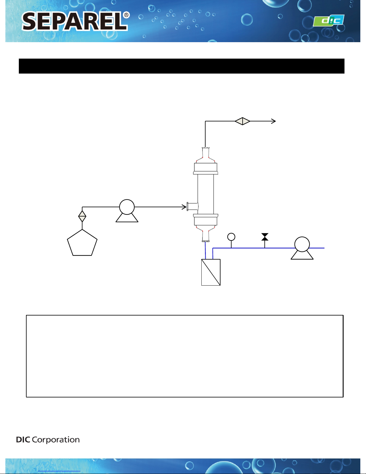
<Example of Installation>
The above example is for your reference.
Depending on use conditions, the above example may not be suitable.
※Optimal flow direction differs by use conditions and the above flow
direction is not always the correct direction. For suitable flow direction,
contact us.
Liquid Feeding
Pump
Liquid Tank
Filter
Vacuum
Pump
Leak Valve
Trap
Vacuum
Meter
Degassing
Module
Filter
3. INSTALLATI ON
Application Materials Product Division
INSTRUCTION MANUAL
Page 9
2) Liquid Out:
● There is a possibili ty that particles ar e generated by the SEPAREL module. To
prevent a problem with such particle occurrence, install a filtration filter behind the
module. The most suitable filtration si ze depends on your use conditions. For more
details, please contact DIC.
● Note that back pressure t o the SEPAREL module sho u l d be avoided.
3)Vacuuming:
● Installed v acuum l i nes must always be facing downwards. If it is pointed upwards,
liquid generated from v apor may block the vacuum li ne.
● Install a trap to detect leaked liquid and to prevent the vacuum pump from damag e
due to vapor and leaked liquid. A trap is also effective in preventing leaked liq uid
from feeding into other modules using the same vacuum li ne.
9
9
Application Materials Product Division
INSTRUCTION MANUAL
3. INSTALLATI ON
1)Liquid In:
● Install security devices, such as a pressure reducing valve and/or safety valve,
to make sure that pressure will not be beyond the maximum operating pressure.
● If you use a solenoid valve, select one which dose not cause sudden opening/shutting.
● If you use two modules in parallel, properly measure the liquid flow into both modules
and ensure that liquid flow is equal.
● If impurities and large particles remain in liquid, install a filter in front of the
SEPAREL module.
● Use RO water or higher quality water for the water supply.
▼In the event water of a water quality lower than RO water is used:
①Please ensure the remaining chloride concentration is, ≦ 1mg/L".
※ You can use water with over 1mg/L, but any warranty period will be determined through
consultations between DIC and the customer.
② To stop performance degradation by fouling in the film surface and clogging by
particle debris, please refer to the following table and use a pre-filter.
Specifically, since soluble compounds included in well wa ter, a branch and tap water are
easy to penetrate filtration and adhere to the surface of the filtration membrane, please
use water in combination with the recommendations in following table.
If you have any questions, please contact DIC Corporation.
Liquid in phase
1.0 micron filter
Page 10
4. START UP
10
10
4-1. Open a valve on the outlet side first. Next, open a valve on the inlet side graduall y t o
make the liquid flow r ate and pressure lower t han the des ignated v alue for ac tual use
until liquid is filled. Do not flow liquid at a very high flow rate nor at a very high pressure.
Even if it is instantaneou s , very high flow rates or press ur e may damage hollow fibers
and cause leakage. For efficient remov al of remainin g air in the liquid ar ea of
SEPAREL modules, filling the liquid with a vacuum is recommended . During the
vacuuming proc ess , c heck the ai r ti g htnes s of the vacuum line and not the air that
is leaked from pipe, connector , and SEPAREL module .
4-2. Observe liquid qual i ty, temperature, and pr ess ur e specified in the s peci fication sheet.
4-3. Do not flow oxidizi ng agents , s uch as hi g hl y concentrated chlorine water and ozone
water, strong acids, strong bases, organic solv ents, oil, or any other liqui d w hich has
not been confirmed as compatible by DIC. The warranty wi l l not apply i f liquid, which
has not been confirmed as compatible by DIC, is used.
4-4. Do not change the flow r ate dr amatic ally in order to ensur e that the hollow fibers ar e
not damaged by drastic pressure fluctuations.
4-5. If vacuum pressure is v er y strong, and condi ti on s are close to a perfect vacuum
situation, stop the vacuum pump when l iquid flow has stopped. S tr ong vacuuming for
an extended period of time w ithout liq uid flow may freeze and damage hollow fibers vi a
vaporization heat and li qui d may leak from the damaged hollow fibers .
4-6. Check the items below periodical ly. If obvious deterioration is found, r eplace w ith a
new degassing module .
Item Points to be Checked
Liquid Inlet Pressure
Do not exceed maximum pressure specified in the specification sheet.
Liquid Temperature ・Do not exceed the maximum temperature specified in the specification sheet.
・Do not fall below the minimum temperature specified in the specification sheet.
Pressure Drop Significant increase fr om initial value may be caused by clogging of hollow fiber
or liquid flow path. In this case, replacement or cleaning is necessary.
Drain/Trap
in Vacuum Line
Continuous leaking of liquid to the vacuum means the product is reaching the
end of its lifetime and replacement with a new degassing module is necessary.
Application Materials Product Division
INSTRUCTION MANUAL
Page 11
5. SHUTOFF AND STORAGE
11
11
5-1. Open the leak valve in the vacuum line. After v acuum is released, stop t he vacuum
pump.
5-2. Close the valve on the ink inlet side and then close the valv e on the liquid outlet side.
5-3. Handling during Shutoff Period:
1) Store under the conditions spec ified by the specificatio n sheet.
2) If the shutoff period is extensiv e, remove the SEP AREL modules and store after
cleaning and dr yi ng completel y. If it is difficult to uninstall t he SEPAREL module, fill it
with liquid that is compatible with SEPAREL and close all li quid and v acuum ports
completely. Even liquid that is compatible with degassing module materials can lead
to bacteria generation if it is left in the module during shutoff periods. The
generation of bacteri a may have a negative i mpact on product quality.
Application Materials Product Division
INSTRUCTION MANUAL
Page 12
12
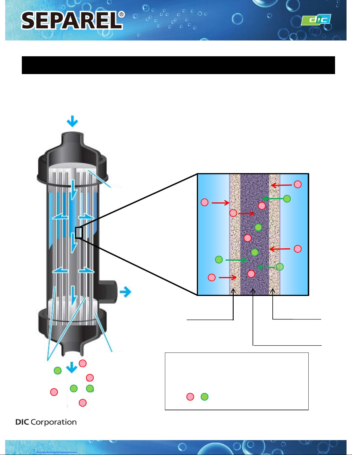
REFERENCE DAT A 1: Basic Principles of Degassing
Sealing Resin
Sealing Resin
Liquid
IN/OUT
Liquid
IN/OUT
Liquid
: Dissolved gas
12
Vacuuming
Liquid
Image of Hollow Fiber Cross-section
Hollow Fiber
Membrane
Hollow Fiber
Membrane
Inside of Hollow Fiber
for Vacuuming
Hollow Fibers
By vacuuming inside the hollow fiber ,
only gas can pass through hollow fiber
membrane and is removed from liq uid.
Application Materials Product Division
INSTRUCTION MANUAL
Page 13
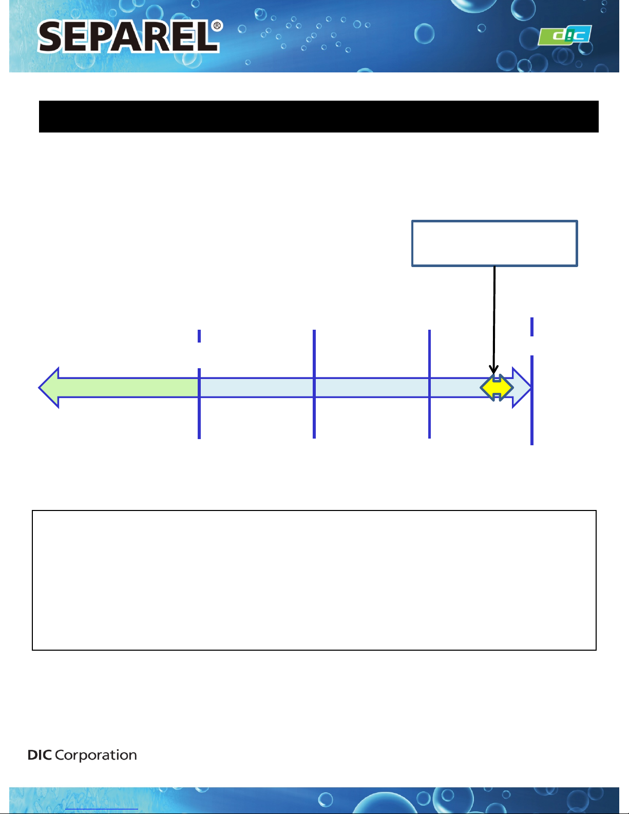
REFRENCE DATA 2: Vacuum Pressure Degree
13
Perfect Vacuum
Atmosphere Pressure
Pressurization Vacuuming
Absolute
Pressure
1 atm
=101.3 kPa(abs)
= 1013 mbar(abs)
= 760 Torr
Gauge
Pressure
- 1 atm
= - 101.3 kPa
= - 1013 mbar
= - 760 Torr
0
0
0.65 atm
= 65.8 kPa(abs)
= 658 mbar(abs)
= 494 Torr
0.35 atm
= 35.5 kPa(abs)
= 355 mbar(abs)
= 266 Torr
- 0.35 atm
= - 35.5 kPa
= - 355 mbar
= - 266 Torr
- 0.65 atm
= - 65.8 kPa
= - 658 mbar
= - 494 Torr
Recommended range of
vacuum pressure degree
(Refer to Reference Data 3)
13
< Absolute Pressure>
For vacuuming conditi ons, ev er y value should be 0 or plus. It cannot be minus.
<Gauge Pressure>
For vacuuming conditions, ev ery value should be 0 or minus. It cannot be plus.
(Reference: Absolute pressure -Gauge pressure =1atm)
※ The value for maximum pressure resistance is indicated by gauge pressure.
● Note that the vacuum pressure degree in our data sheet is mainly indicated
by absolute pressure, not by gauge pressure.
Application Materials Product Division
INSTRUCTION MANUAL
Page 14
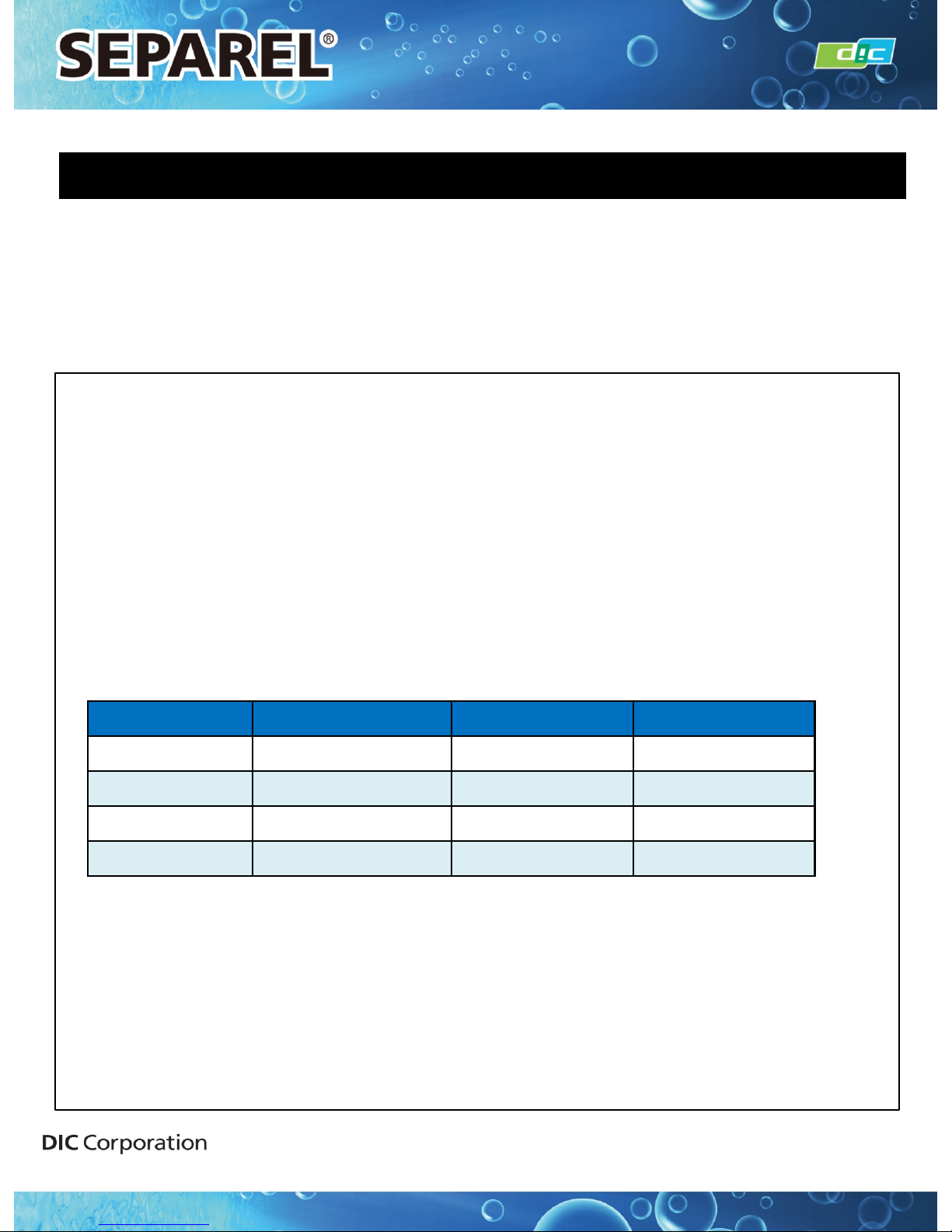
REFRENCE DATA 3: Setting Value of Vacuum Pressure Degree
14
Temperature (℃)
kPa(abs) Torr mbar
15 1.7 12.8 17
20 2.3 17.3 23
25 3.2 24 32
30 4.2 31.5 42
14
1. For Water or Aqueous Liquid
Recommended Deg ree of Vacuum: 5kPa(abs) ~ 10kPa(abs)
= 50mbar(abs) ~ 100mbar(abs)
※The above pressure is the recommended value when using the module at 15-30℃.
When using the module at temperatures lower than 15℃ or higher than 30℃,
please contact DIC for more details.
※The above vacuuming pr essur e is not suitable for every application. Dependi ng on
applications, c ompositio n, and target degassing performance , the most suitable
vacuuming v alue may be differe nt from the abov e v alue.
<Reference: Saturated Water Vapor Pressure>
2. For Non-Aqueous Liquid.
Recommended Vacuuming Degree: We recommend setting w eaker degrees (hig her
in
value) than the recommended saturated vapor pressure of the liquid.
Ex:In cases where saturated vapor pressure is 8kPa(abs), we recommend a weaker vacuum
degree than 10kPa(abs).
As the vacuum pressure degree approaches a perfect vacuum, degassing
performance is improved. However, if the vacuum pressure degree is too strong
yet close to perfect pressure, liquid may evaporate and penetrate through the
membrane. As a result, the composition of liquids may change. Therefore, DIC
recommends following the exact vacuum pressure degree.
Application Materials Product Division
INSTRUCTION MANUAL
Page 15
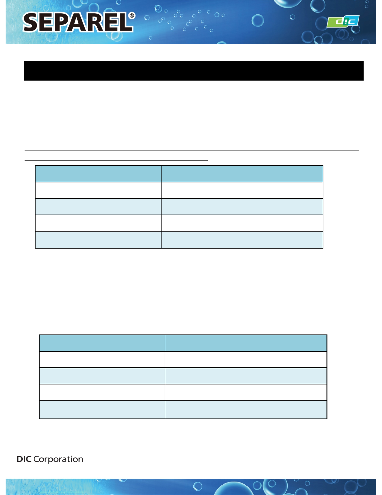
REFERENCE DATA 4: Range of Liquid Flow Rate
15
Product Maximum Pressure Resistance
EF-MICRO 0.2 MPa (= 2 bar)
EF-G2 Series 0.2 MPa (= 2 bar)
EF-G3 Series 0.2 MPa (= 2 bar)
EF-G5 Series 0.2 MPa (= 2 bar)
Product
Flow area
EF-MICRO 0.5 ~ 10 ml/min
EF-G2 series 1 ~ 60 ml/min
EF-G3 series 5 ~ 300 ml/min
EF-G5 series 10 ~ 1500 ml/min
15
Make sure that the l i q ui d feedi n g pressure at the inlet por t i s low er than t he max i mum
pressure value descr ibed in the specifica tio n sheet.
If the feeding pressure exceeds the max imum v alue, even momenta ril y, the hollow fiber may
be damaged and i nk may leak i nto the vacuum line.
※ The warranty will not apply in cases w here liq uid feeding pres sure exc eeds the maximum
pressure value specified in the specification sheet,
Even if liquid feeding pressure i s lower than the specified maximum pressure, an i ncr eas ed
flow rate will cause lesser degassing performan ce. On the other hand, if the flow rate is too
low, degassing cannot be efficient. Therefore, DIC supplies recommend ed flow ranges in the
table below.
※ The recommended flow range below w as calculated w hen using wat er. In the case of
high viscosity liquid, a suitable flow rang e w ill be more narrow.
Application Materials Product Division
INSTRUCTION MANUAL
Page 16
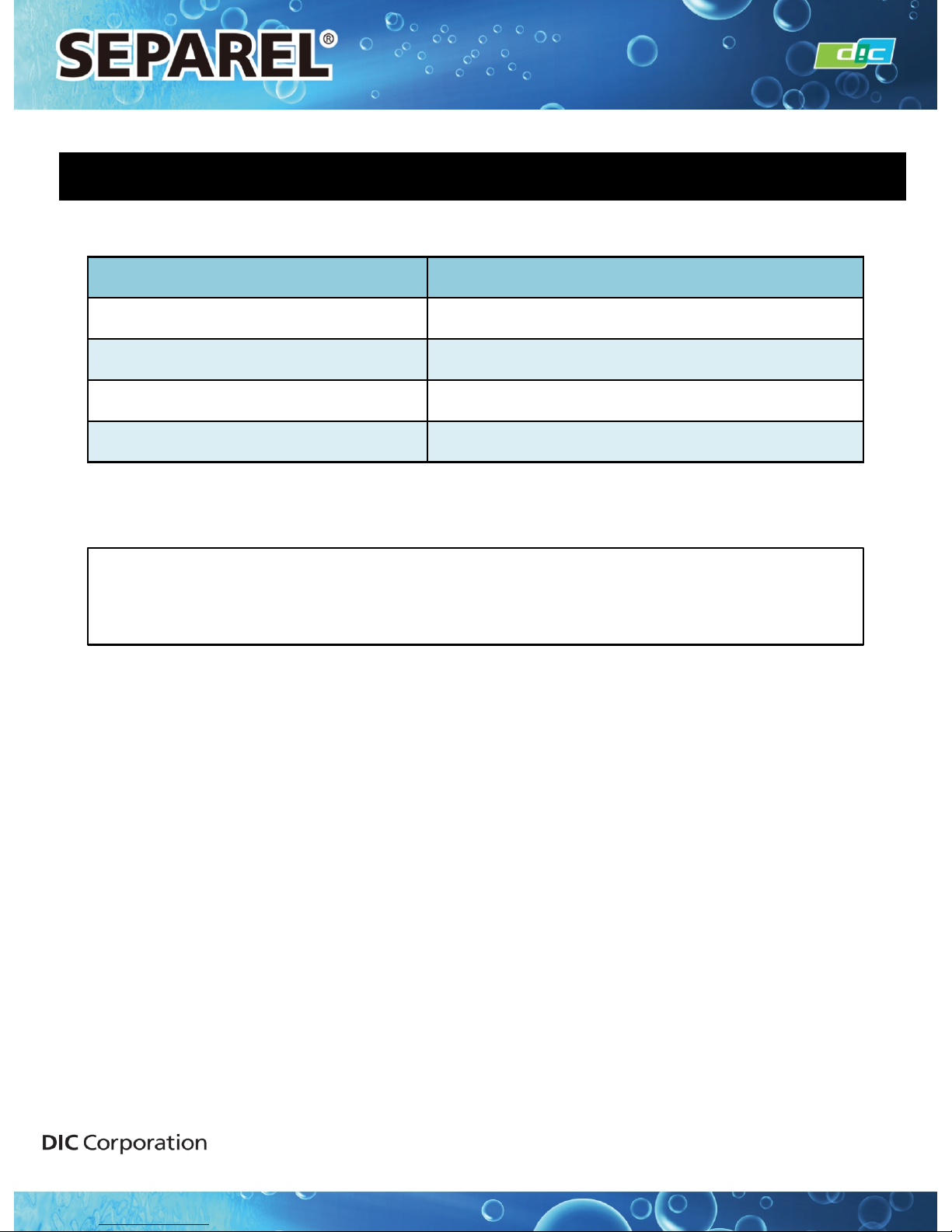
REFERENCE DATA 5: Inner Volume
16
Product
Inner Volume at Liquid Part
EF-MICRO
Approx. 4 ml
EF-G2 Series
Approx. 11 ml
EF-G3 Series
Approx. 40 ml
EF-G5 Series
Approx. 85 ml
The above values are for reference and are not guaranteed values.
Actual volume may differ by connection type.
16
Application Materials Product Division
INSTRUCTION MANUAL
Page 17
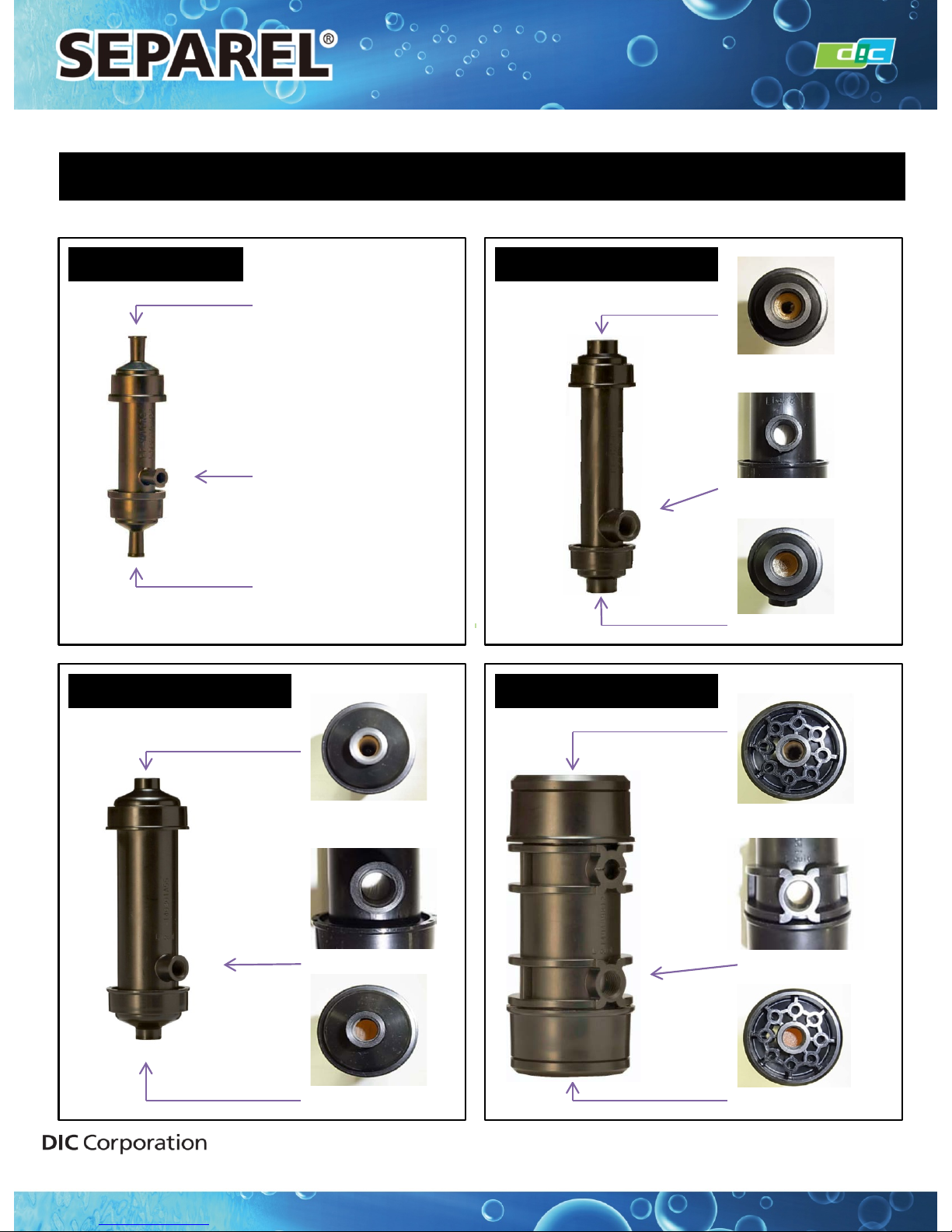
17
Liquid IN/OUT
Liquid IN/OUT
V acuum Port
EF–MICRO
REFERENCE DATA 6: Image of Connecting Port
EF–G2 Series
Liquid IN/OUT
Liquid IN/OUT
V acuum Port
EF–G3 Series
V acuum Port
Liquid IN/OUT
17
EF–G5 Series
V acuum Port
Liquid IN/OUT
Liquid IN/OUT
Liquid IN/OUT
INSTRUCTION MANUAL
Application Materials Product Division
Page 18
Contacts
18
DIC Corporation
Membranes Sales Department
Application Materials Product Division
DIC Building, 7-20, Nihonbashi 3-chome, Chuo-ku, Tokyo 103-8233, J apan
TEL: +81(3)6733-5944
FAX: +81(3)6733-5960
URL: http://www.separel.com
North, Central, and South America
DIC International (USA), LLC
Address: 35 Waterview Boulevard,
Parsippany, NJ 07054, U.S.A.
TEL: +1-973-404-6600
FAX: +1-973-404-6601
Europe and Middle East
DIC Europe GmbH
Address: Immermannstraße 65 D
D-40210 Düsseldorf, Germany
TEL: +49-211-1643-0
FAX: +49-211-1643-88
China
DIC (Shanghai) Co., Ltd
Address: 12thFl. Metro Plaza, No 555 Lou Shan
Guan Road, Shanghai 200051,
People’s Republic of China
TEL: +86-21-6228-9911
FAX: +86-21-6241-9269
Korea
DIC Korea Corporation
Address: 3rdFl., The Korea Chamber of
Commerce & Industry, 39, Sejong-Daero,
Jung-Gu, Seoul, 100-743, Republic of Korea
TEL: +82-2-317-6200
FAX: +82-2-752-1059
Oceania,
Asia except for Japan, China, and Korea
DIC Asi a Pacific Pte. Ltd
Address: 19 International Road,
Jurong, Singapore 619623
TEL: +65-6261-0644
FAX: +65-6265-5256
<Worldwide Contacts Outside of Japan>
Taiwan
DIC T aiwan Ltd.
Address: Room 801, 8thFl., Chang An Bldg.,
No. 18, Chang An East Road, Section 1,
Taipei, Taiwan
TEL: +886-2-2551-8621
FAX: +886-2-2562-9240
Application Materials Product Division
INSTRUCTION MANUAL
 Loading...