

SEOWON INTECH SWC-5100 User Manual

VoIP CPE
SWC-5100 Series User Manual
SEOWON INTECH

Contents
Introduction to the Product
------------------------------------- 3
-------------------------------------------
Functional
Features
LED Information
Rear Side Information
Configuration
Network Configuration
Package Configuration
PC Configuration(Windows XP)
3
---------------------------------------------- 3
----------------------------------------- 4
------------------------------------------------ 5
----------------------------------------- 5
----------------------------------------- 6
----------------------------------- 7
How
to
check
your
IP
address
CPE built-in Web ServerAccess
CPE Setup on the web page
LAN(LAN Configuration)
LAN(MAC Address)
-----------------------------------
10
-------------------------------- 11
------------------------------------ 12
--------------------------------------- 12
------------------------------------------- 13
LAN(Status)
Switch(Bridge & Router)
Switch(VLAN)
Switch(Filter)
Switch(Status)
VoIP(SIP Server Setting)
VoIP(RTP & VoIP Setting)
------------------------------------------------
13
--------------------------------------- 14
----------------------------------------------- 15
----------------------------------------------- 16
---------------------------------------------- 19
--------------------------------------- 20
-------------------------------------- 22
----------------------------------------
VoIP(Call
Forwarding)
VoIP(Status)
Application(Firewall)
Application(DMZ & Port Forwarding)
Application(VPN pass through)
Admin(Version)
Admin(Password)
A
dmin(CPE Upgrade
)
23
----------------------------------------------- 23
------------------------------------------ 24
------------------------------ 25
---------------------------------- 27
---------------------------------------------- 28
-------------------------------------------- 28
----------------------------------------- 2
9
(
pg )
Admin(Reboot/Default Setting)
OTA
System Log
Wizard
Trouble Shooting
Operating Information
9
---------------------------------- 30
--------------------------------------------------- 32
----------------------------------------------------------- 33
--------------------------------------------------------------------- 34
-------------------------------------------- 36
Product Warranty and Customer Support
Warranty Information
----------------------------------------
37
-------------------------- 38
----------------------------------------- 39

Introduction to the Product
This product receives external WiMAX signals to construct in-building infrastructure on a
WiMAX network, and is covered by Ethernet network internally. The product serves as a
relay as well as an internet router.
However, the purpose of the product is mostly to supply signals to users, with the
emphasis being its relay rather than its modem functions.
It is also a wired and wireless internet router that enables several systems to share a
single internet address supplied by a high-speed internet service provider.
Function Features
IEEE802.16e WiMAX
Support
Wave1 = DL : 10Mbps / UL : 4Mbps
Wave2 = DL : 30Mbps / UL : 6Mbps
IEEE802.3u Ethernet Support 10/100Mbps wired LAN connectable
Functional
Features
RJ-11 VoIP Support
1 x RJ
-11
for Analog Telephone Service
LAN Port 1 Port 10/100Mbps Ethernet Switch built-in
Cable Auto Sense Straight (Direct) or Cross Cable auto sensing
NAT function
Supports up to 253 wired and wireless connections and internet
router*
Firewall function Manages basic firewall and IP/Port/based access
LED Information
LED Indicator Function
PWR Power Supply status (On at Power ON)
LAN ON when connected to PC, Flashing at communication
3
PHONE ON when connected to Telephone, Flashing at communication
RSSI
Representation WiMAX received signal strength indication(RSSI), on when
the mode was selected router.
Introduction to the Product
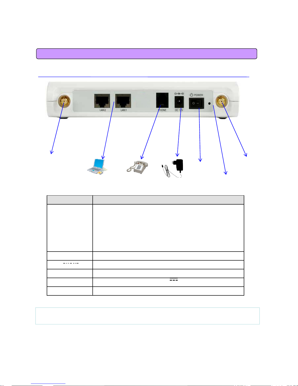
Rear Side Information
Antenna1
WiMAX
Antenna2
WiMAX
Power
Item Details
External Antenna
Antenna1 : WiMAX Diversity
A
ntenna2 : WiMAX Main
Diversity
Main
Switch
Hardware
Reset
PC
TelePhone
Power Adapter
Separable external antenna
User external type antenna attachable
* Antenna Classification
- 2.3G : M23
- 2.5G : M25
- 3.5G : M35
LAN PC or Hub connection
PHONE
Teleph
one connection
DC 12V Power Adapter connection (DC 12V 2.0A )
POWER Power On/Off Switch (Switch between On/Off by pressing right or left)
RESET Restore the VoIP CPE Factory Default
4
[Note] If you lost LOGIN password fo
r
routerorIP address afterchange, use the Reset
switch to restore its original Factory Default settings.

Configuration
Network Configuration
Telephone
To
verify
the
normal
operation
of
the
router
,
check
the
following
LEDs
after
connecting
the
router, modem, and PC with a LAN cable, as follows:
LED Normal Operation Actions to take if not illuminated
PWR ON when connecting adapter Check for adapter power failure
ON when cable is connected
LAN
normally
Check cable connection and PC power supply
PHONE
On when Phone cable is connected
normally
Check cable connection and Telephone
WiMAX
RSSI
Represents WiMAX received signal
strength indication (RSSI), ON when
in router mode
Check that router mode is selected
If one or more LED lights is not in “normal operation”, take the actions specified in the
table.
Install a router after connecting to the network.
If normal connection between router and PC is checked, you have to set up the PC and
router.
PC setup is to control network configuration for Windows 98, Windows 2000, or Windows
XP to use the Internet while the PC is connected to a router.
5
Routersetup is to connect a routerto the Internet. Please refe
r
to the CPE Setup chapte
r
.
Configuration
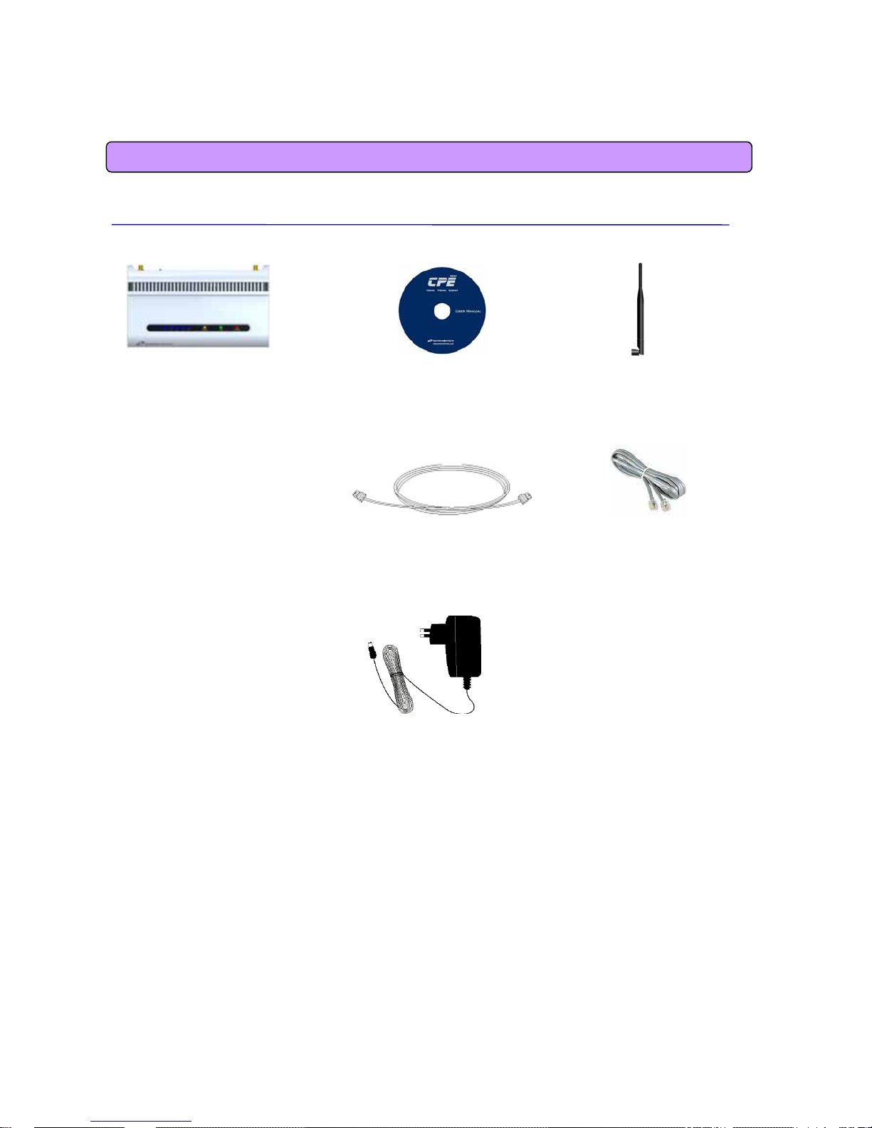
Package Contents
Main Unit CD Antenna X 2
UTP Cable Telephone Cable
Adapter
6
Configuration
PC Configuration (Windows XP)
This procedure is used to restore Windows XP’s TCP/IP setup to the default values. If
Windows has just been installed for the first time on the PC, no changes should be
required, but you should check to confirm that all values are normal according to the
following.
After completing the TCP/IP setup of the PC, connect PC and CPE with a LAN cable and
turn CPE on before Windows starts up to determine whetheran IP address is obtained
from CPE automatically.
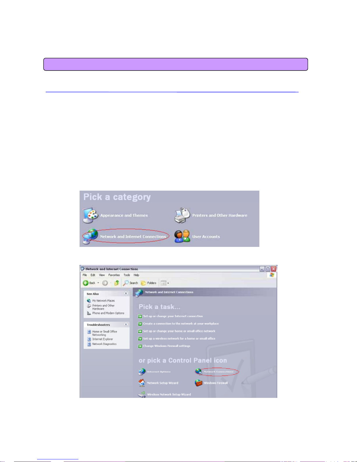
• Click the Windows Start button, and select Settings >> Control Panel from the menu.
• Double-click the “Network Connection” icon in the Control Panel.
<Double-click the Network and Internet Connections> …
7
<Double-click the Network Connection>

• Double-click the Local Area Connection from the Network Connection list to select it.
Configuration
<Double-click the Local Area Connection>
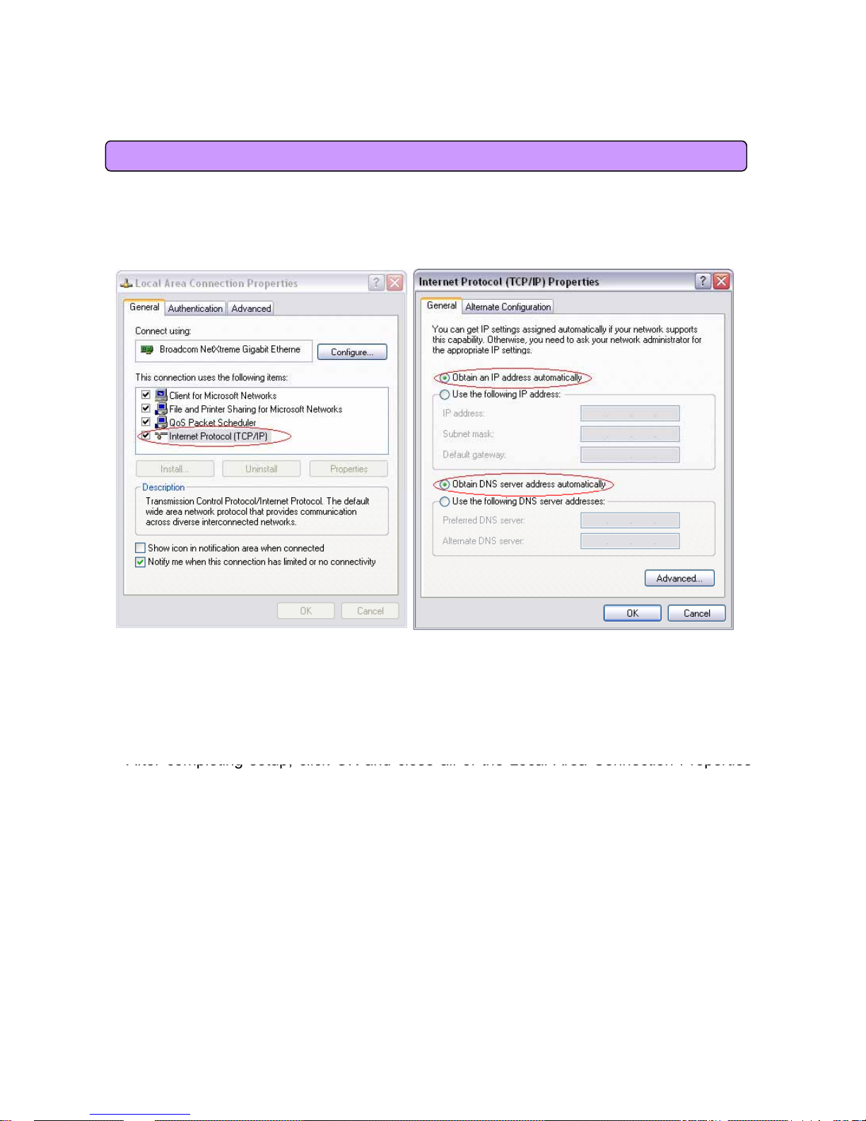
• Click “Properties” in the Local Area Connection Status window.
8
<Click Properties>
Configuration
•Double-clic
k
Int
erne
t
Prot
oco
l
(TCP/IP)
t
oopenitsProperties window, an
d
th
en selec
t
“Obtain an IP address automatically” and “Obtain a DNS Server address automatically”.
<Select the
‘Obtain an IP address automatically’ ,
‘Obtain a DNS Server address automatically’
and click OK>
<Double-click TCP/IP >
•
After
completing
setup,
click
OK
and
close
allofthe
Local
Area
Connection
Properties
windows.
• When TCP/IP setup is completed, an IP address is automatically assigned by CPE. For
automatic assignment, the PC and the CPE should be connected with a LAN cable. If they
are not connected with a cable, connect them with a LAN cable and restart the PC.
• You can check the automatic IP address assignment by using the ipconfig command
from the Command Prompt.
9
 Loading...