

Introduction to the Product
Thank you for choosing SLC-120T42OGA, Outdoor CPE.
SLC-120T42OGA is oers better performance over Outdoor CPE given
that LTE reception is not impeded.
It oers easy installation, reliable network connection, advanced
security & authentication features, and more.
Please read this User Manual carefully to learn about the SLC-120T42OGA.
It will help you to meet your diverse communication needs, at home
and at the oce.
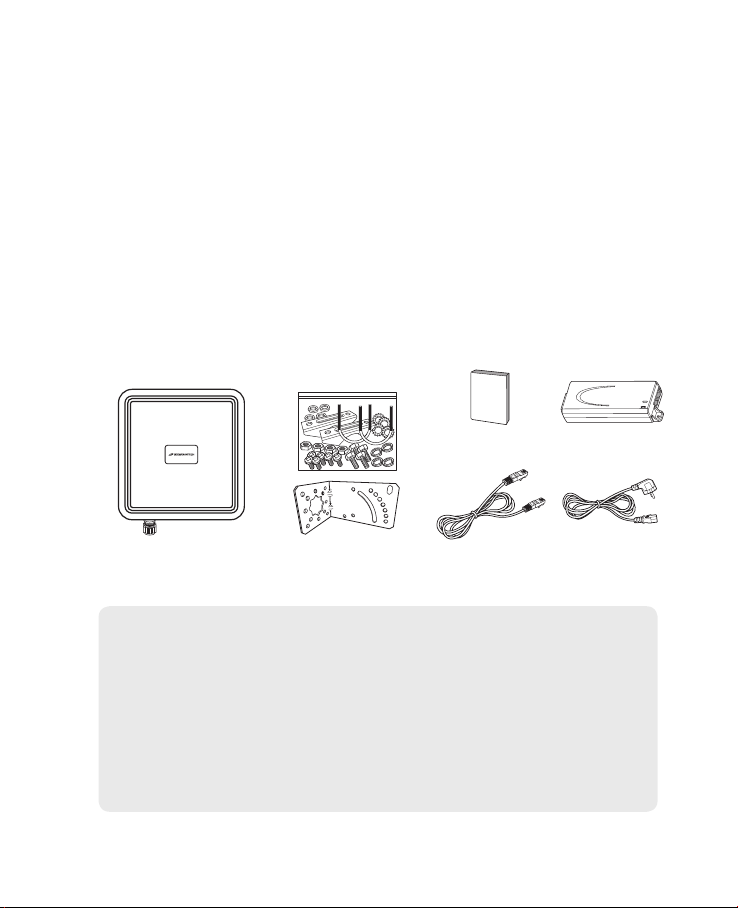
1. Package Contents
User Manual PoE
Main Unit Mounting Kits
Note :
- Please note that it performs the best with the accessories which are contained
in the package, and the manufacturer will not be responsible for defects/
damage or shortened product life resulting from the use of product in
conjunction or connection with accessories, products, or ancillary/peripheral
equipment not approved by the manufacturer.
- Please use the product with accessories which are contained in the package.
- The components, appearance of the product, specications and etc. are subject
to change without prior notice for performance improvement.
LAN Cable
AC Code
(100~240V)
1
2. Functional Features
Function Features
Model Name SLC-120T42OGA
Technical Standard
Frequency Band
LTE
Max. Transmit Power
Antenna
HPBW (3dB Beam Width)
External Interface
LED
Indicators
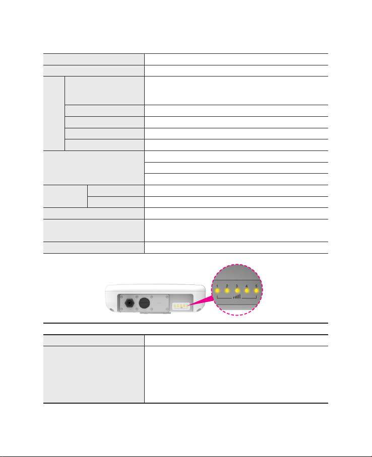
3. LED Presentation
Operating Temperature -40° to +70°C
Power Supply
Dimension 275(W) x 285(D) x 78(H)mm
Power Sharing with Signal Strength
Signal Strength 5 LEDs with 1 color (5 Level display)
LTE 3GPP Release 12, Category 15, TDD Conguration 2
DL : 580Mbps (4x4 MIMO-2Layer, 4CA, 256QAM),
UL : 30Mbps (2CA, 64QAM)
43(3650 ~3700MHz)
23dBm (+3, -4dB)
Internal Patch Antenna, 4x4 MIMO, 10.59dBi Gain
+/- 45 degree Dual Linear / Directional
1 x Gigabit Ethernet RJ45 LAN port
1 x Mini USIM Card Slot
1 x Reset button
IEEE 802.3af, Giga PoE Injector
(Input : 100~240VAC, Output : 48V/0.45A)
3. LED Presentation
Status icon & LED indicator
Boot in progress Blinking Yellow LED (1), Blinking period = 1sec
Number of LED depending on signal strength
- Most Strong Signal : Five yellow LED
Network connection
- Strong Signal : Four yellow LED
- Middle Signal : Three yellow LED
- Weak Signal : Two yellow LED
- Very Weak Signal : One yellow LED
2
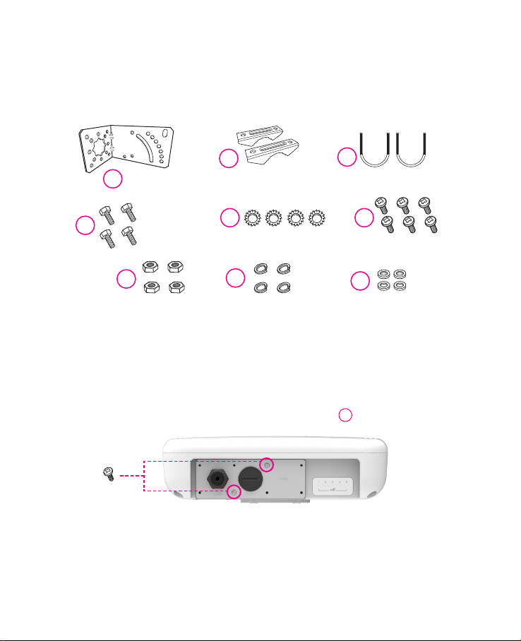
4. Mounting Conguration
Package List
You need the following :
2
One Bracket Mounting Bar(2ea) Mounting U-Bolt(2ea)
1
4
Bolts(4ea)
7
Nuts(4ea) Spring Washers(4ea)
5
Toothed lock washer(4ea)
8
5. Assembly sequence optimization
Step 1
Remove the two Bolt M3 from the outdoor CPE.
* Remaining 6 screws are enclosed in the mounting kits as
(2ea)
3
6
Bolt M3(6ea)
9
Washer(4ea)
6
3
Step 2 (Installing USIM Card)
Carefully insert the USIM Card into USIM slot.
USIM
card
CAUTION :
The surface of IC(metal) should be facing downward
from the USIM card.
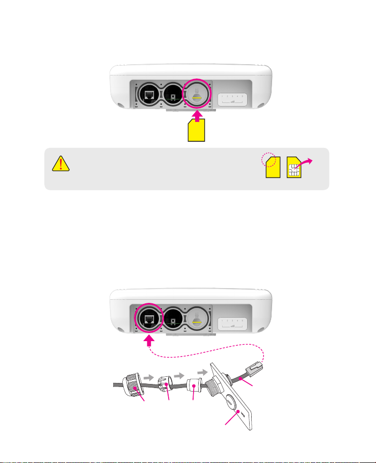
Step 3
Remove the cap by turning. Then follow the next steps as shown below.
1. Remove the cap.
2. Put A, B, Cap and Aluminum plate to cable line in order.
3. Plug the cable line into the LAN hole of outdoor CPE.
4. Connect A and B in order.
5. Lastly, connect Cap to Aluminum plate by turning.
Cable line
Cap B A
Aluminum plate
4
IC
USIM card

Step 4
Assemble the Aluminum plate and outdoor CPE using the screws Bolt M3(8ea).
6
(8ea)
LAN
Cable line
Step 5
Attach item 1 to the back side of the device using item 4 as shown.
(Insert item 5 into item 4 before installing)
5
4
1
Step 6
Install the device to pole using item 2 and 3, tighten the bracket by using item
7, 8 and 9.
7 8 9
3
2
5
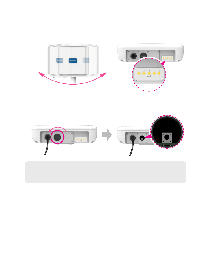
Step 7
Adjust the device, using the dierent position on the bracket.
Check the LED light (1~5).
RESET Button(When the device turned On)
- Press the reset button once : Device reboot
- Press and hold the reset button 5sec : Factory reset
Turn left: Open
Turn right: Closed
Note : If you forget the Login password for the Outdoor CPE or IP address after
making changes, use the reset button to restore the Outdoor CPE to its
original factory default settings.
RESET Button
6
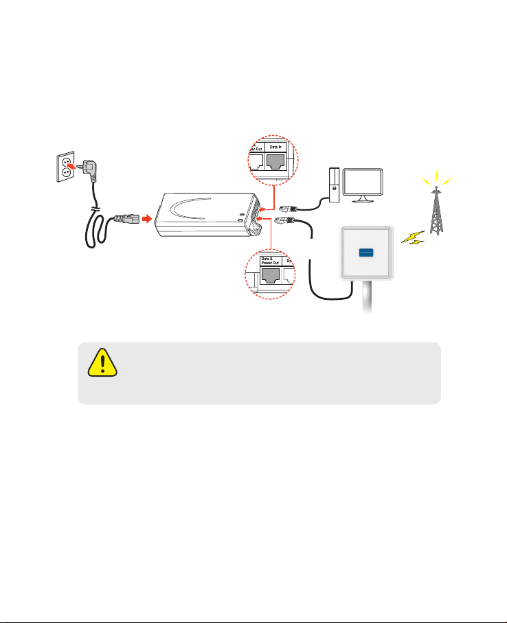
Conguration
1. Network Conguration
External Network
Data IN
LAN Cable for PC or
AC Code
100~240V
AC IN
Safety precaution : Do not allow the PSE adapter to get wet.
Keep it inside of the building. Liquid could damage your device or
cause you injuries. Water damage can void your warranty.
It is recommended to use the accessory provided.
PoE Injector
Data &
Power Out
Install a Outdoor CPE after connecting to the network.
If normal connection between Outdoor CPE and PC is checked, you have to
set up the PC and Outdoor CPE. The purpose of PC setup is to control
network conguration for Windows Windows 7/8/10 or Mac OS X to use the
Internet while the PC is connected to a Outdoor CPE.
The purpose of Outdoor CPE setup is to connect the Outdoor CPE to the
Internet. Please refer to the Outdoor CPE Setup chapter.
WiFi Access Point
LAN
Cable
Outdoor CPE
Internet
7
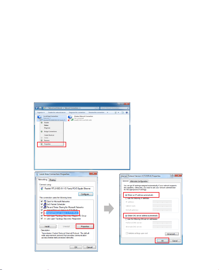
2. PC Conguration(Windows 7)
Most computers already have TCP/IP conguration enabled. For your computer to support CPE, please verify that the IP address and DNS settings are
automatically generated in the Local Area connection of your Internet Protocol (TCP/IP) properties.
• In a Windows environment :
• Click “Start” button >> Click “Control Panel” >> Click “Network and Inter
net Connection” >> Click “Network Connection” >> Right-click “Local Area
Connection” and S elect “Properties” >> Select “Internet Protocol 4 (TCP/
IPv4)” and click “Properties” >> Select “obtain an IP address automatically”
and “obtain DNS server address automatically” >> Click “OK” .
8
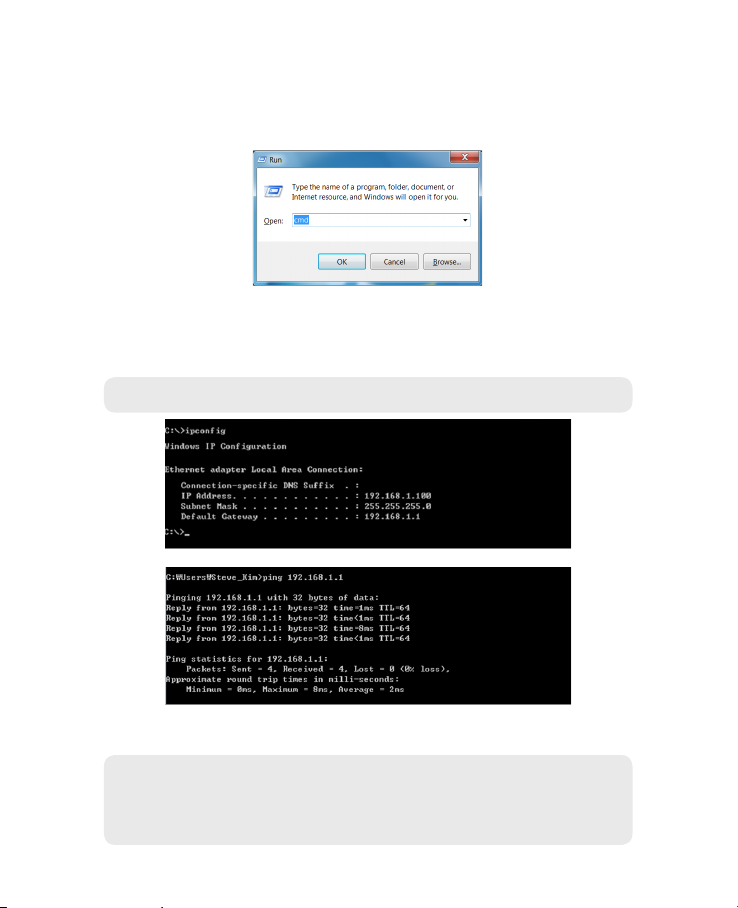
3. How to check your IP address
• Open the Command Prompt window by clicking the “Start” button and
selecting “Run”. Enter “cmd”, and click the “OK” button.
<Run cmd>
• When the Command Prompt window opens, enter the “ipcong”
command to verify the IP address, Subnet mask, and Gateway, which are
automatically assigned to your PC.
Note : PCs connected to Device will receive own assigned IP address.
<Verify IP address>
• If the host can reach the device using the ping command, the device has
successfully attached.
Note : If an IP address is not assigned, check the following. and Then restart
the PC and check whether an IP address is assigned.
- LAN cable connection between PC and CPE
- Check TCP/IP setup details
9
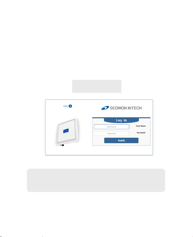
Log-in to Web Interface
The Web Browser allows you to manage the Device and to view.
In the Address Bar :
• Go to WEB “http://192.168.1.1” then press ENTER to access the login screen.
• The default one is “user” for both User Name and Password.
• You can change the Password after logging in
(User Name and Password are case-sensitive).
Username = user
Password = user
Note : The Web Interface can be accessed by entering http://192.168.1.1 in
the Address Bar, regardless of the network connection status.
When there is no input for 1 hour after your login to the Web Interface,
you will be automatically logged out.
10

Setup on the web page
1. Dashboard
• Select “Dashboard” from the left menu.
• You can see the Mobile Network, LTE, Network, Firewall, Monitoring and
Firmware Information.
11
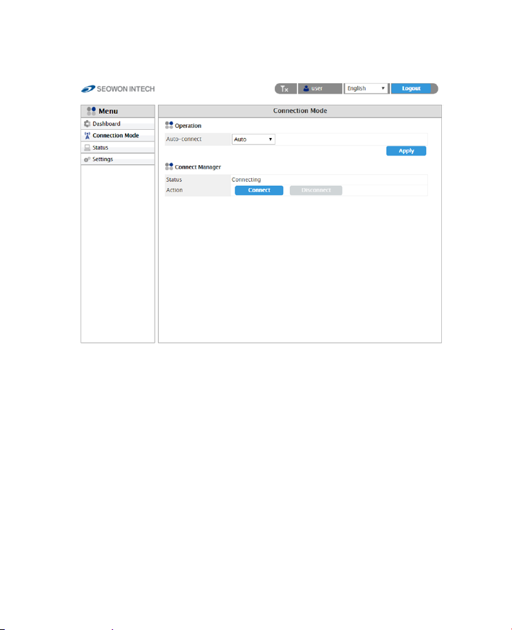
2. Connection Mode
• Select “Connection Mode” from the left menu.
• You can select operation mode Auto or Manual.
• You can see the status of Connect Manager.
• Start LTE Connection by clicking “Connect” or stop by clicking
“Disconnect” button.
12
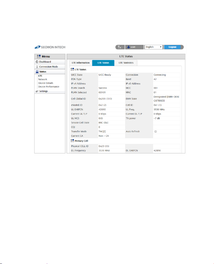
3. Status
3.1 LTE
• Select “Status” → “LTE” from the left menu.
• You can see the LTE Information, Status and Statistics by clicking each tab.
13
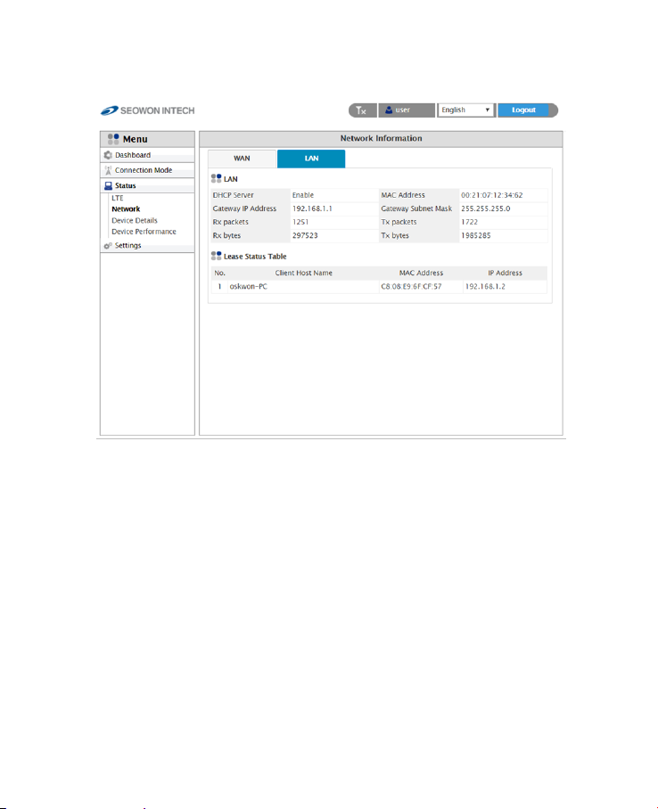
3.2 Network
• Select “Status” → “Network” from the left menu.
• You can see the WAN, LAN status and Lease Status Table.
14
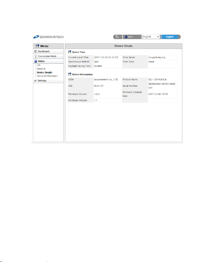
3.3 Device Details
• Select “Status” → “Device Details” from the left menu.
• You can see the device time and device information.
15

3.4 Device Performance
• Select “Status” → “Device Performance” from the left menu.
• You can see the system performance such as CPU, memory, UL/DL data
rate and rewall status.
16

4. Settings
4.1 LTE
4.1.1 Cell Selection
• Select “Settings” → “LTE ” → “Cell Selection” from the left menu.
• You can change the mode “Full Band” or “Frequency”.
• You can see the status of band and you can change the band.
• Check the box and click the “Apply” button.
17

4.1.2 Cell Lock
• Select “Settings” → “LTE ” → “Cell Lock” from the left menu.
• You can add current cell to lock or delete cell to unlock in the list.
• You can manually add cell by clicking “Add+” button.
• Finish setup by clicking the “Apply” button.
18

4.1.3 SIM Management
• Select “Settings” → “LTE ” → “SIM Management” from the left menu.
• You can see the current status of SIM.
• Only the button operation is enabled to match the current status.
- If you SIM card is locked, PIN Status shows “PIN ENABLED NOT VERIFIED”.
- Then you should enter the PIN code and click the “Verify” button.
- After success unlock PIN then you can attached the LTE network.
- You can set new PIN code by unblocking with PUK code.
- If you failed to unblock PIN, you never use this SIM card.
19

4.1.4 Default PDN
• Select “Settings” → “LTE ” → “Default PDN” from the left menu.
• You can set the PDN data such as APN, Authentication Type and PDN
type(IPv4, IPv6).
• Put in the data to box then click “Apply” button.
• If you set wrong data, the device doesn’t attach the LTE network.
20

4.1.5 Multiple PDN
• Select “Settings” → “LTE ” → “Multiple PDN” from the left menu.
• You can set the multiple PDN data for IMS, admin, App service.
• Select “Cid”, check “Enable”, put in the data to box then click “Apply”
button.
21

4.1.6 Internet MTU
• Select “Settings” → “LTE ” → “Internet MTU” from the left menu.
• You can change the internet MTU size.
• Put in the data to box then click “Apply” button.
22

4.1.7 IPv6 Settings
• Select “Settings” → “LTE ” → “IPv6 Setup” from the left menu.
• You can Enable or Disable IPv6 function by selecting the list.
• You can set DHCPv6 Auto-conguration mode by selecting the list.
• You can set DNS Server Address Mode to “Auto” or “Manual”.
• After selecting the each mode, put in the data to all boxes.
• Finish setup by clicking the “Apply” button.
23

4.2 Network
4.2.1 Switch
• Select “Settings” → “Network” → “Switch” from the left menu.
• You can select Switch Mode to “NAT” or “BRIDGE”.
• Finish setup by clicking the “Apply” button.
24

4.2.2 DHCP Server
• Select “Settings” → “Network” → “DHCP Server” from the left menu.
• Congure DHCP Server Setting.
- IP address is used in the LAN cable that the device manages.
- Setup IP address in “Gateway IP Address/ Gateway Subnet Mask” text boxes.
- Initial Value is “192.168.1.1/255.255.255.0” and only the last byte in “Gateway
Subnet Mask” box can be modied.
- Finish setup by clicking the “Apply” button.
25

4.2.3 Port Management : DMZ/Port Forwarding/Port Triggering
• Select “Settings” → “Network” → “DMZ” from the left menu.
• Congure DMZ(Demilitarized Zone)
- Select whether or not to enable the DMZ function.
- You can set “Redirect ICMP To The Host” and “Exclude Web Server Port”.
- Set the IP address to have all ports opened in “Private LAN IP Address” content.
- Finish setup by clicking the “Apply” button.
26

• Select “Settings” → “Network” → “Port Forwarding” from the left menu.
• Congure Port Forwarding
- Enter the Name.
- Select one of the listed Protocols (BOTH, TCP, UDP).
- Enter Start Port, End Port, Destination IP and Destination Port.
- Click the “Add” button when you nished.
- You can change the data by clicking “Edit” or “Del” button in the list.
27

• Select “Settings” → “Network” → “Port Triggering” from the left menu.
• Congure Port Triggering
- Enter the Name.
- Select one of the Port Type(RANGE or SINGLE).
- Select Trigger Protocol and Open Protocol(ALL, TCP, UDP)
- Enter Trigger Port Range and Open Port Range.
- Click the “Add” button when you nished.
- You can change the data by clicking “Edit” or “Del” button in the list.
28

4.2.4 VPN Conguration
• Select “Settings” → “Network” → “VPN Conguration” from the left menu.
• You can set VPN mode by selecting “GRE”, “ L2TP” or “PPTP”.
• After selecting the mode, put in the data to all boxes.
• Then click “Add” button.
• Finish setup by clicking the “Apply” button.
29

4.2.5 VPN Passthrough
• Select “Settings” → “Network” → “VPN Passthrough” from the left menu.
• The device support 2 types of service : PPTP Service, L2TP/IPSEC Service.
• Select the type(s) of VPN pass-through to use with the checkboxes.
• Finish setup by clicking the “Apply” button.
30

4.2.6 UPnP
• Select “Settings” → “Network” → “UPnP” from the left menu.
• Select whether or not to Enable the Universal Plug & Play function.
• Finish setup by clicking the “Apply” button.
• When UPnP Client is connecting, it will appear on the Client List.
31

4.2.7 QoS
• Select “Settings” → “Network” → “QoS” from the left menu.
• To set the QOS, check “Shaping”.
The desirable service quality class can be set.
- Setup download speed in “Download(kbps)” text box.
- By selecting “Upload” and “Download” in the list, you can adjust each speed.
- Setup IP address/mask, protocol, port and rate.
- Click the “Add” button after setting all items.
- Finish setup by clicking the “Apply” button.
32

4.2.8 DDNS
• Select “Settings” → “Network” → “DDNS” from the left menu.
• Set the DDNS environment
- If you want to set the DDNS, check “Enable” in the checkbox to enter necessary
inputs.
- After entering all the necessary information for DDNS Setting, nally, click the
“Apply” button to nish setting.
33

4.3 Firewall
4.3.1 Basic
• Select “Settings” → “Firewall” → “Basic” from the left menu.
• If you want to use the default Firewall function, check the “Enable”
checkbox.
• You can set other rewall rules as Ping, HTTP, HTTPS login and Multicast
Filter.
• If you want to use SIP ALG function, check enable and type port number
in the box.
• For lter set up, select the lter item (IP, MAC, ACCEPT, DROP, BOTH, etc)
and ll the blank.
• Finish setup by clicking the “Add” button.
• You can also delete the lter rule by clicking “remove” button in the
Filter List.
34

4.4 User Management
4.4.1 Account
• Select “Settings” → “User Management” → “Account” from the left menu.
• Set the password to be given to the administrator who manages the
device.
• Enter the new password.
• Finish setup by clicking the “Apply” button.
35

4.4.2 Language
• Select “Settings” → “User Management” → “Language” from the left menu.
• Select the Language.
• Finish setup by clicking the “Apply” button.
36

4.4.3 Restore Default
• Select “Settings” → “User Management” → “Restore Default” from the
left menu.
• To initialize all congurations the device, click “Apply” button.
• If you want to save, remove or reset this conguration click the button.
• The device will reboot automatically and it takes about 70 seconds.
37

4.4.4 Reboot
• Select “Settings” → “User Management” → “Reboot” from the left menu.
• To reboot by software, click “Apply” button.
• The device will reboot automatically and it takes about 60 seconds.
38

4.4.5 Date and Time
• Select “Settings” → “User Management” → “Date and Time” from the
left menu.
• Congure Time Zone.
- If you want to set the NTP Client, select “Enable”.
- Set the “Time Server”.
- Select the “Time Zone Select”.
- If you want to set the “Daylight Saving”, check “Enable Daylight Saving”.
- If you want to set the duration of “Daylight Saving”, set the below.
- Finish setup by clicking the “Apply” button.
- Changed conguration is applied immediately.
39

4.4.6 Remote Management
• Select “Settings” → “User Management” → “Remote Management” from
the left menu.
• You can set HTTP Server port and HTTPS Server port.
• If you want to set https server, check “Enable” and type Port Number.
• Finish setup by clicking the “Apply” button.
40

4.5 Firmware Management
4.5.1 Software
• Select “Settings” → “Firmware Management” → “Software” from the
left menu.
• Select the rmware le by clicking the “Browse…” button.
• To start the rmware update, click “Update” button.
• The device will be restart automatically.
41

4.6 Monitoring
4.6.1 Iperf
• Select “Settings” → “Monitoring” → “Iperf” from the left menu.
• You can use iperf by clicking the “Enable” button.
• Set the all data in the eld.
• Finish setup by clicking the “Apply” button.
• Whenever you want to see the result, click “Refresh” button.
42

4.6.2 Diagnostic
• Select “Settings” → “Monitoring” → “Diagnostic” from the left menu.
• Congure the Ping.
- If you want to test ping, enter IP Address to “IP Address (URL)”.
- Set the all data in the eld.
- Click the “Apply” button to test.
- The results come out below.
43

• Congure the Trace route.
- If you want to test trace route, enter IP Address to “IP Address (URL)”.
- Select the “Set Maximum TTL” and “Set the number of queries at each TTL”.
- If you want to see report consisting of IP Address, check the “Report IP
Address Only”.
- Click the “Apply” button to test.
- The results come out below.
44

4.6.3 Log
• Select “Settings” → “Monitoring” → “Log” from the left menu.
• The device support 2 types of log : System log and Kernel log.
• Congure System log.
- Check “Enable” in “System log Enable/Disable”.
- Check “System log” in “View System Log”.
- Click “Refresh” button or “Clear” button for each action.
- If you want to download the log to your PC, click “Download” button.
45

• Congure Kernel log.
- Check “Kernel log” in “View System Log”.
- Check “Detailed” or “Simple” in below.
- Click “Refresh” button or “Clear” button for each action.
- If you want to download the log to your PC, click “Download” button.
Restrictions on the operation of base and fixed stations.
This equipmentis subject ti the registrations rules of Section 90.1331 for restrictions
on the operation of base and fixed stations. It can only be sold marketed to licenses
and cannot be sold to the general public. The license holder is responsible, prior to
operation, to register the device in the database and only operate the equipment at
the registered fixed location and not at any other location.
46

SEOWON INTECH.CO.,LTD.
R&D Center 69, LS-ro 115beon-gil, Gunpo-si, Gyeonggi-do, Korea 15809
TEL +82-31-428-9531/ FAX +82-31-428-9537 / E-mail sales@seowonintech.co.kr / www.seowonintech.co.kr/en
The content in this document can be modied without prior notice for improving performance or function of deviec.
copyright © 2018 by SEOWONINTECH ALL Pictures cannot be copied without permission.
 Loading...