

SEOWON INTECH SLC-120T42O Quick Guide
www.seowonintech.co.kr
Quick Installation Guide
LTE Network Outdoor CPE
SLC-120T42OGA
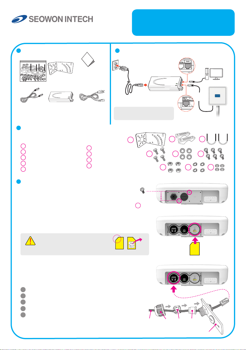
Package Contents Connection Diagram
AC Code
(100~240V)
AC IN
NOTE : It is recommended to
use the accessory provided.
PoE Injector
Mounting Kits
LAN Cable PoE
Quick
Installation
Guide
AC Code
(100~240V)
Mounting Conguration
You need the following :
1
One Bracket
2
Mounting Bar (2ea)
3
Mounting U-Bolt (2ea)
4
Bolts (4ea)
5
Toothed lock washer (4ea)
6
Bolt M3 (6ea)
7
Nuts (4ea)
8
Spring Washers (4ea)
9
Washer (4ea)
1
4
7 8 9
Assembly sequence optimization
Step 1
Remove the two Bolt M3 from the outdoor CPE.
* Remaining 6 screws are enclosed in the mounting kits as
Step 2 (Installing USIM Card)
Carefully insert the USIM Card into USIM slot.
(2ea)
6
2
5
Data IN
Data &
Power Out
LAN Cable for PC or
WiFi Access Point
LAN
Cable
Outdoor CPE
3
6
CAUTION : The surface of IC(metal)
should be facing downward from
the USIM card.
USIM card
Step 3
Remove the cap by turning. Then follow the next steps
as shown below.
1
Remove the cap.
2
Put A, B, Cap and Aluminum plate to cable line in order.
3
Plug the cable line into the LAN hole of outdoor CPE.
4
Connect A and B in order.
5
Lastly, connect Cap to Aluminum plate by turning.
IC
Cable line Cap B A
Aluminum plate
USIM
card
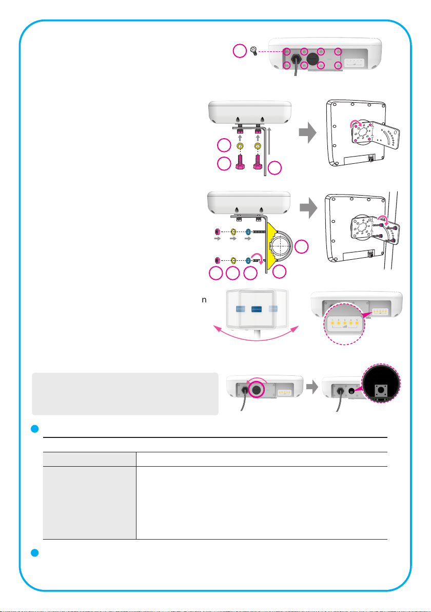
Step 4
Assemble the Aluminum plate and outdoor CPE
using the screws Bolt M3(8ea).
Step 5
Attach item 1 to the back side of the device
using item 4 as shown.
(Insert item 5 into item 4 before installing)
6
(8ea)
LAN
Cable line
5
4
Step 6
Install the device to pole using item 2 & 3,
tighten the bracket by using item 7 & 8 & 9.
8 97
Step 7
Adjust the device, using the dierent position
on the bracket. Check the LED light (1~5).
RESET Button (
- Press the reset button once : Device reboot
- Press and hold the reset button 5sec : Factory reset
NOTE : If you forget the Login password for the
Outdoor CPE or IP address after making changes,
use the reset button to restore the Outdoor CPE to its
original factory default settings.
When the device turned On)
Turn left: Open
Turn right: Closed
LED Presentation
Status icon & LED indicator
Boot in progress Blinking Yellow LED (1), Blinking period = 1sec
Number of LED depending on signal strength
- Most Strong Signal : Five yellow LED
Network connec-
tion
- Strong Signal : Four yellow LED
- Middle Signal : Three yellow LED
- Weak Signal : Two yellow LED
- Very Weak Signal : One yellow LED
1
3
2
RESET Button
Log-in to Web Interface
- Go to WEB "http://192.168.1.1" then press ENTER to access the login screen.
- The default one is user for both User Name and Password.
 Loading...