

SEOWON INTECH ESLC-120T42OGA User Manual
User manual
SLC-120T42OGA
LTE Network Outdoor CPE
www.seowonintech.co.kr

Contents
Introduction to the Product
1. Package Contents
2. Functional Features
3. LED Presentation
4. Mounting Conguration
5. Assembly sequence optimization
Conguration
1. Network Conguration
2. PC Conguration(Windows 7)
3. How to check your IP address
Log-in to Web Interface
Setup on the web page
1. Dashboard
2. Connection Mode
3. Status
3.1 LTE
3.2 Network
3.3 Device Details
3.4 Device Performance
4. Settings
4.1 LTE
4.1.1 Cell Selection
4.1.2 Cell Lock
4.1.3 SIM Management
4.1.4 Default PDN
4.1.5 Multiple PDN
4.1.6 Internet MTU
4.1.7 IPv6 Settings
4.2 Network
04
4.2.1 Switch
05
4.2.2 DHCP Server
05
4.2.3 Port Management
06
4.2.4 VPN Conguration
06
4.2.5 VPN Passthrough
4.2.6 UPnP
4.2.7 QoS
10
4.2.8 DDNS
10
4.3 Firewall
11
4.3.1 Basic
4.4 User Management
13
4.4.1 Account
14
4.4.2 Language
14
4.4.3 Restore Default
4.4.4 Reboot
15
4.4.5 Date and Time
4.4.6 Remote Management
16
4.5 Firmware Management
17
4.5.1 Software
18
4.6 Monitoring
19
4.6.1 Iperf
4.6.2 Diagnostic
4.6.3 Log
20
21
Troubleshooting
22
Safety Information
23
24
Legal Information
25
26
Warranty Information
27
28
29
32
33
34
35
36
37
38
39
40
41
42
43
44
45
46
48
50
51
52
53
03

Introduction to the Product
Thank you for choosing SLC-120T42OGA, Outdoor CPE.
SLC-120T42OGA is oers better performance over Outdoor CPE given
that LTE reception is not impeded.
It oers easy installation, reliable network connection, advanced
security & authentication features, and more.
Please read this User Manual carefully to learn about the SLC-120T42OGA.
It will help you to meet your diverse communication needs, at home
and at the oce.
1. Package Contents
User Manual PoE
04
Main Unit Mounting Kits
Note :
- Please note that it performs the best with the accessories which are contained
in the package, and the manufacturer will not be responsible for defects/
damage or shortened product life resulting from the use of product in
conjunction or connection with accessories, products, or ancillary/peripheral
equipment not approved by the manufacturer.
- Please use the product with accessories which are contained in the package.
- The components, appearance of the product, specications and etc. are subject
to change without prior notice for performance improvement.
LAN Cable
AC Code
(100~240V)
2. Functional Features
Function Features
Model Name SLC-120T42OGA
Technical Standard
Frequency Band
LTE
Max. Transmit Power
Antenna
HPBW (3dB Beam Width)
External Interface
LED
Indicators
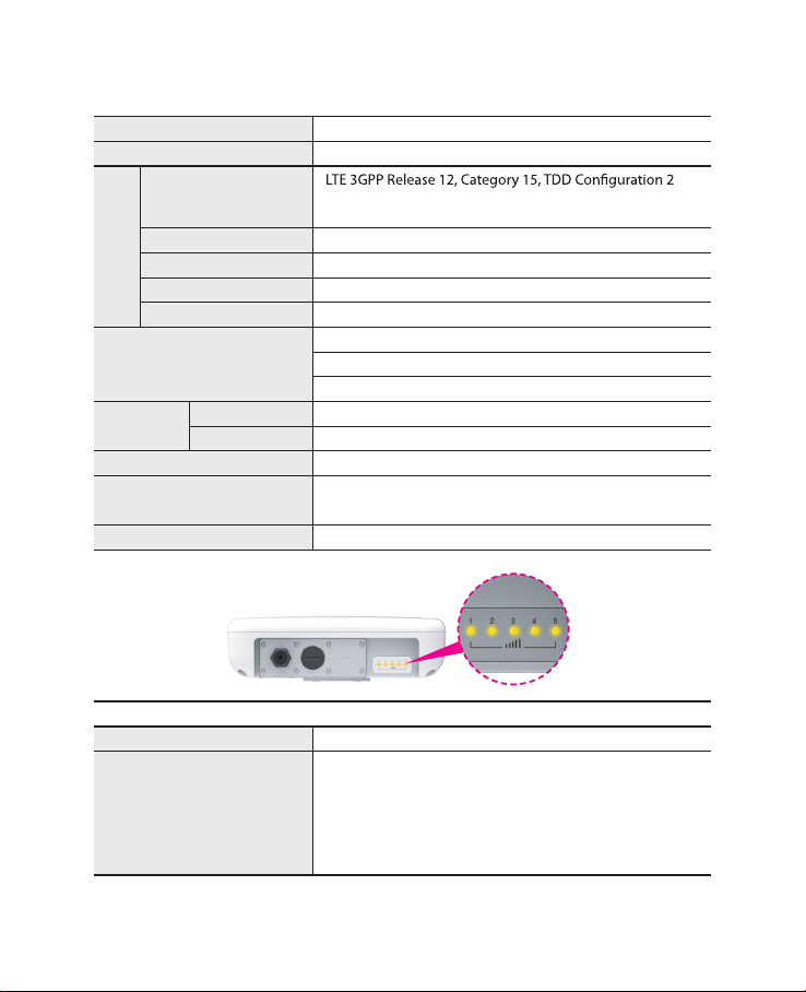
3. LED Presentation
Operating Temperature -40° to +70°C
Power Supply
Dimension 275(W) x 285(D) x 78(H)mm
Power Sharing with Signal Strength
Signal Strength 5 LEDs with 1 color (5 Level display)
DL : 580Mbps (4x4 MIMO-2Layer, 4CA, 256QAM),
UL : 30Mbps (2CA, 64QAM)
43(3650 ~3700MHz), 48(3550 ~3700MHz)
11dBm
Internal Patch Antenna, 4x4 MIMO, 10.59dBi Gain
+/- 45 degree Dual Linear / Directional
1 x Gigabit Ethernet RJ45 LAN port
1 x Mini USIM Card Slot
1 x Reset button
IEEE 802.3af, Giga PoE Injector
(Input : 100~240VAC, Output : 48V/0.45A)
3. LED Presentation
Status icon & LED indicator
Boot in progress Blinking Yellow LED (1), Blinking period = 1sec
Number of LED depending on signal strength
- Most Strong Signal : Five yellow LED
Network connection
- Strong Signal : Four yellow LED
- Middle Signal : Three yellow LED
- Weak Signal : Two yellow LED
- Very Weak Signal : One yellow LED
05
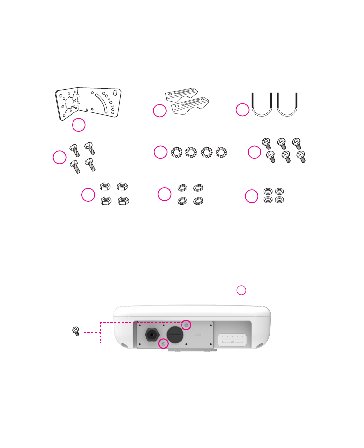
4. Mounting Conguration
Package List
You need the following :
2
One Bracket Mounting Bar(2ea) Mounting U-Bolt(2ea)
1
4
Bolts(4ea)
7
Nuts(4ea) Spring Washers(4ea)
5
Toothed lock washer(4ea)
8
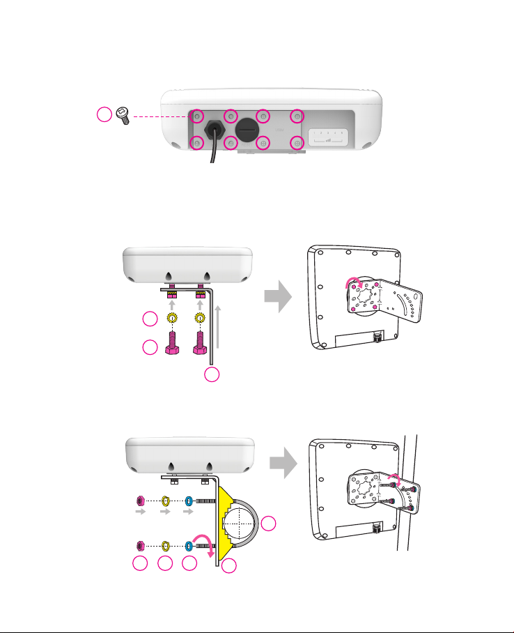
5. Assembly sequence optimization
Step 1
Remove the two Bolt M3 from the outdoor CPE.
* Remaining 6 screws are enclosed in the mounting kits as
(2ea)
3
6
Bolt M3(6ea)
9
Washer(4ea)
6
06
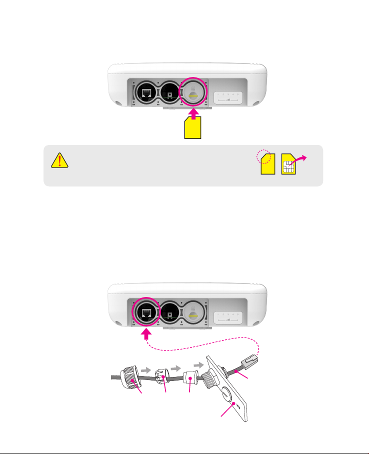
Step 2 (Installing USIM Card)
Carefully insert the USIM Card into USIM slot.
USIM
card
CAUTION :
The surface of IC(metal) should be facing downward
from the USIM card.
USIM card
Step 3
Remove the cap by turning. Then follow the next steps as shown below.
1. Remove the cap.
2. Put A, B, Cap and Aluminum plate to cable line in order.
3. Plug the cable line into the LAN hole of outdoor CPE.
4. Connect A and B in order.
5. Lastly, connect Cap to Aluminum plate by turning.
Cable line
Cap B A
Aluminum plate
IC
07
Step 4
Assemble the Aluminum plate and outdoor CPE using the screws Bolt M3(8ea).
6
(8ea)
LAN
Cable line
Step 5
Attach item 1 to the back side of the device using item 4 as shown.
(Insert item 5 into item 4 before installing)
5
4
1
Step 6
Install the device to pole using item 2 and 3, tighten the bracket by using item
7, 8 and 9.
08
7 8 9
3
2

Step 7
Adjust the device, using the dierent position on the bracket.
Check the LED light (1~5).
RESET Button(When the device turned On)
- Press the reset button once : Device reboot
- Press and hold the reset button 5sec : Factory reset
Turn left: Open
Turn right: Closed
Note : If you forget the Login password for the Outdoor CPE or IP address after
making changes, use the reset button to restore the Outdoor CPE to its
original factory default settings.
RESET Button
09
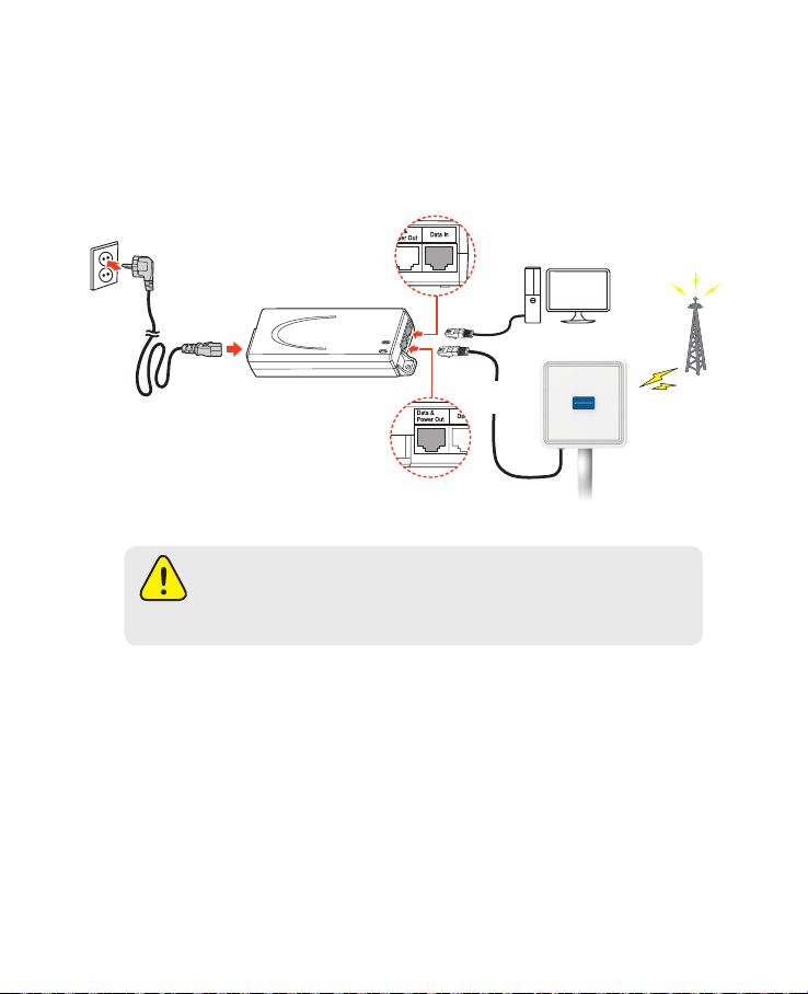
Conguration
1. Network Conguration
External Network
Data IN
LAN Cable for PC or
AC Code
100~240V
AC IN
Safety precaution : Do not allow the PSE adapter to get wet.
Keep it inside of the building. Liquid could damage your device or
cause you injuries. Water damage can void your warranty.
It is recommended to use the accessory provided.
PoE Injector
Data &
Power Out
Install a Outdoor CPE after connecting to the network.
If normal connection between Outdoor CPE and PC is checked, you have to
set up the PC and Outdoor CPE. The purpose of PC setup is to control
network conguration for Windows Windows 7/8/10 or Mac OS X to use the
Internet while the PC is connected to a Outdoor CPE.
The purpose of Outdoor CPE setup is to connect the Outdoor CPE to the
Internet. Please refer to the Outdoor CPE Setup chapter.
WiFi Access Point
LAN
Cable
Outdoor CPE
Internet
10
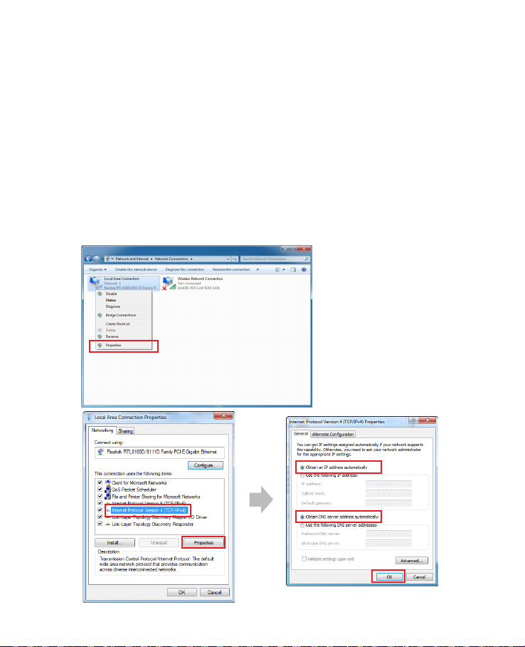
2. PC Conguration(Windows 7)
Most computers already have TCP/IP conguration enabled. For your computer to support CPE, please verify that the IP address and DNS settings are
automatically generated in the Local Area connection of your Internet Protocol (TCP/IP) properties.
• In a Windows environment :
• Click “Start” button >> Click “Control Panel” >> Click “Network and Inter
net Connection” >> Click “Network Connection” >> Right-click “Local Area
Connection” and Select “Properties” >> Select “Internet Protocol 4 (TCP/
IPv4)” and click “Properties” >> Select “obtain an IP address automatically”
and “obtain DNS server address automatically” >> Click “OK” .
11
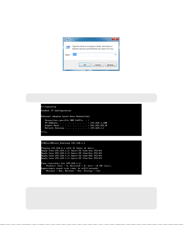
3. How to check your IP address
• Open the Command Prompt window by clicking the “Start” button and
selecting “Run”. Enter “cmd”, and click the “OK” button.
<Run cmd>
• When the Command Prompt window opens, enter the “ipcong”
command to verify the IP address, Subnet mask, and Gateway, which are
automatically assigned to your PC.
Note : PCs connected to Device will receive own assigned IP address.
<Verify IP address>
• If the host can reach the device using the ping command, the device has
successfully attached.
Note : If an IP address is not assigned, check the following. and Then restart
the PC and check whether an IP address is assigned.
- LAN cable connection between PC and CPE
- Check TCP/IP setup details
12
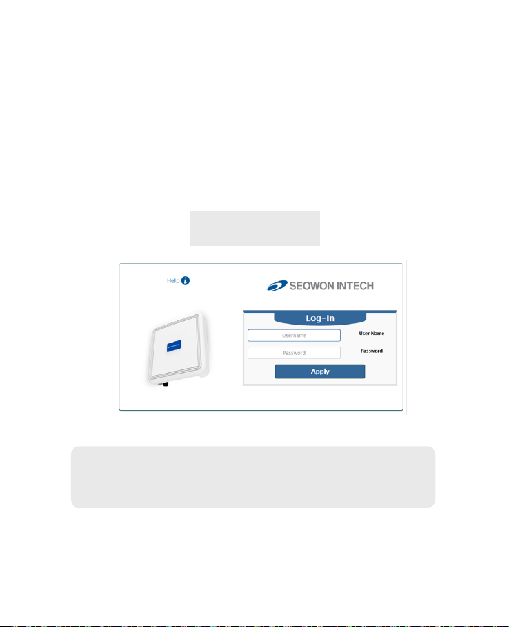
Log-in to Web Interface
The Web Browser allows you to manage the Device and to view.
In the Address Bar :
• Go to WEB “http://192.168.1.1” then press ENTER to access the login screen.
• The default one is “user” for both User Name and Password.
• You can change the Password after logging in
(User Name and Password are case-sensitive).
Username = user
Password = user
Note : The Web Interface can be accessed by entering http://192.168.1.1 in
the Address Bar, regardless of the network connection status.
When there is no input for 1 hour after your login to the Web Interface,
you will be automatically logged out.
13
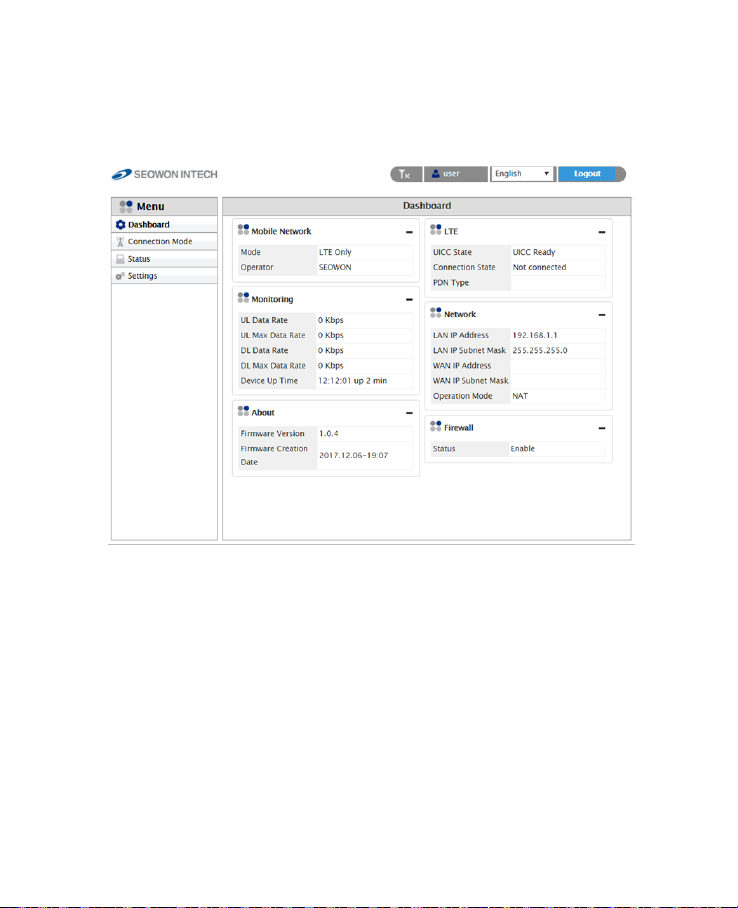
Setup on the web page
1. Dashboard
• Select “Dashboard” from the left menu.
• You can see the Mobile Network, LTE, Network, Firewall, Monitoring and
Firmware Information.
14
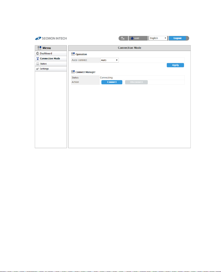
2. Connection Mode
• Select “Connection Mode” from the left menu.
• You can select operation mode Auto or Manual.
• You can see the status of Connect Manager.
• Start LTE Connection by clicking “Connect” or stop by clicking
“Disconnect” button.
15
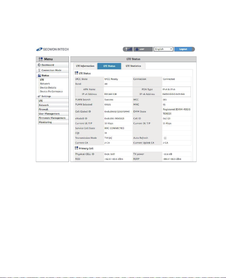
3. Status
3.1 LTE
• Select “Status” → “LTE” from the left menu.
• You can see the LTE Information, Status and Statistics by clicking each tab.
16

3.2 Network
• Select “Status” → “Network” from the left menu.
• You can see the WAN, LAN status and Lease Status Table.
17
 Loading...