

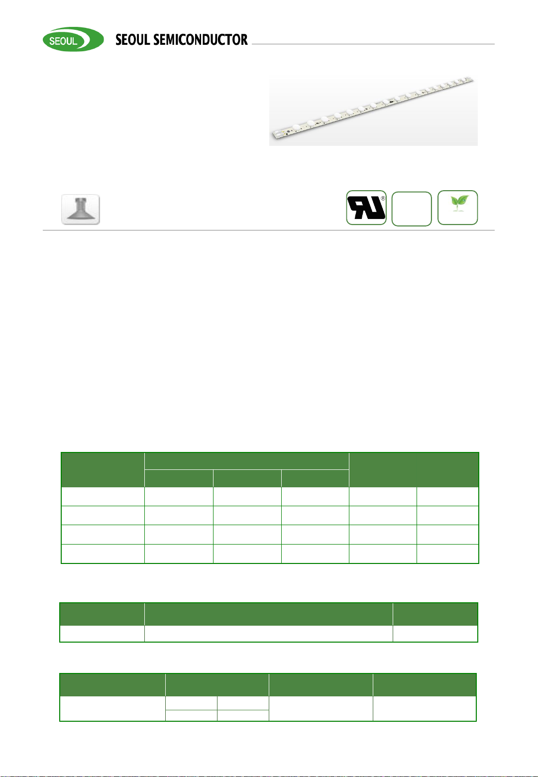
1
WICOP 2-Outdoor
Product Data Sheet
Product Brief
Description
Key Applications
Features and Benefits
Rev0.4.1, December 14, 2017
www.seoulsemicon.com
Preliminary
SMJQ-L51W68XX-ET
WICOP 2 – 25W
• Employed WICOP package on board
• Lens on board with multiple light pattern
optimal.
• Pock in connector in built
• DLC 4.1 premium complied
• Multiple CCT and CRI combination
provide widely application
• Modular design concept, easily expend
to multitude application
• High lumen density
• High efficiency
• Extreme long life span
RoHS
LM-80
• Bay light
• Shop light
Table 1-1. Product Selection - Flux
Bin
Flux
Unit Remark
Min. Typ. Max.
D62
3260 3620 -
Lm
CRI=80
C,E rank
D41
3070 3410 -
Lm
CRI=80
F rank
D62
3260 3620 -
Lm
CRI70
C,E rank
D41
3070 3410 -
Lm
CRI=70
F rank
Table 1-2. Product Selection - CCT
Bin CCT Unit
X05 X=C,E,F K
Table 1-3. Product Selection – CRI and V
F
Bin CRI V
F
Unit
XD#0
X=8 80
DC51 VDC
X=7 70

2
Rev0.4.1, December 14, 2017
www.seoulsemicon.com
Product Data Sheet
WICOP 2-Outdoor
Table of Contents
Index
• Product Brief
• Table of Contents
• Performance Characteristics
• Absolute Maximum Ratings
• Relative Spectral Distribution
• Color Bin Structure
• Naming Rule
• Performance Characteristics
• Mechanical Dimensions
• Application Guide
• Marking Information
• Label Information
• Packing Introduction
• Precaution for Use
• Storage before use
• Company Information
• Revision History
3
Rev0.4.1, December 14, 2017
www.seoulsemicon.com
Product Data Sheet
WICOP 2-Outdoor
Performance Characteristics
Table 2. Electro Optical Characteristics , IF=500mA , Ta = 25ºC
(1)
Parameter Symbol
Value
Unit Mark
Min. Typ. Max.
Luminous Flux Ф
V
[2]
3260 3620 -
lm
CRI=80
C,E rank
3070 3410 -
CRI=80
F rank
3260 3620 -
CRI70
C,E rank
3070 3410 -
CRI=70
F rank
Correlated Color
Temperature
[3]
CCT
4700 5000 5300
K
C Rank
3700 4000 4200 E Rank
3200 3500 3700 F Rank
CRI Ra
70 - - 80 - - -
Input Voltage
[4]
V
in
49.3 51.9 V
DC
V
Power Consumption P 25 W IF=500mA
Efficacy LPW 145 IF=500mA
Viewing Angle 2Θ
1/2
30 D
deg.
60 D
90 D
Ellipse 36 30D+60D
SE 40D+130D
Notes :
(1) The above data were tested at Ta = 25ºC.
(2) Ф
V
is the total luminous flux output measured with an integrated sphere.
(3) Correlated Color Temperature is derived from the CIE 1931 Chromaticity diagram.
(4) To use the module properly, recommend to drive the module by a Constant Current Source
(CCS). But the Maximum output voltage of the CCS should be limited by refering this sheet.
4
Rev0.4.1, December 14, 2017
www.seoulsemicon.com
Product Data Sheet
WICOP 2-Outdoor
Absolute Maximum Ratings
Table 3. Absolute Maximum Ratings, IF=500mA , Ta = 25ºC
(1)
Parameter Symbol Unit Value Remark
Power Consumption P W 32.5 P
type
= 25W
Driving Current
(2)
I
F
mA 650 I
F_type
= 500mA
Operating Temperature
(3)
T
C
ºC - 20 ~ 80 Reference point
Storage Temperature T
stg
ºC - 40 ~ 85 With no power
ESD Sensitivity
- KV
±4 IEC Air
±2 HBM
Notes :
(1) All guarantee are based on the Absolute Maximum Ratings listed.
(2) Please use a Constant Current Source (CCS) to drive the module, the typical VFof module is
49.3 VDC and V
F_MAX
is 51.9 VDC, respectively.
(3) Operating temperature was tested at the assigned Tc point on the PCB.
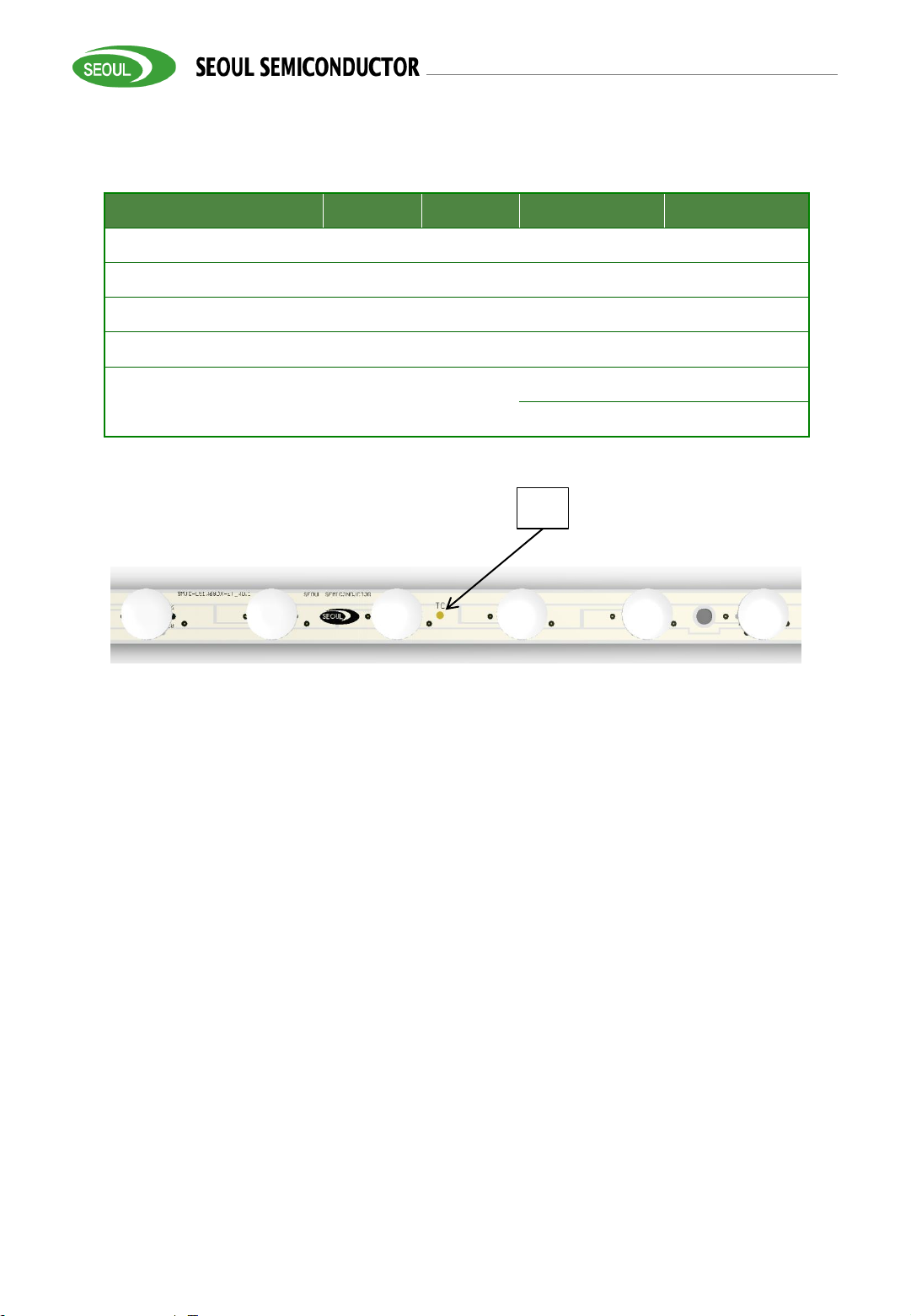
(4) To ensure the module works properly, DO NOT let the Tc upper than 80 ºC;
ILLUSTRATION 1: How to predict components temperature
(4)
Recommended Tc testing point
Tc
5
Rev0.4.1, December 14, 2017
www.seoulsemicon.com
Product Data Sheet
WICOP 2-Outdoor
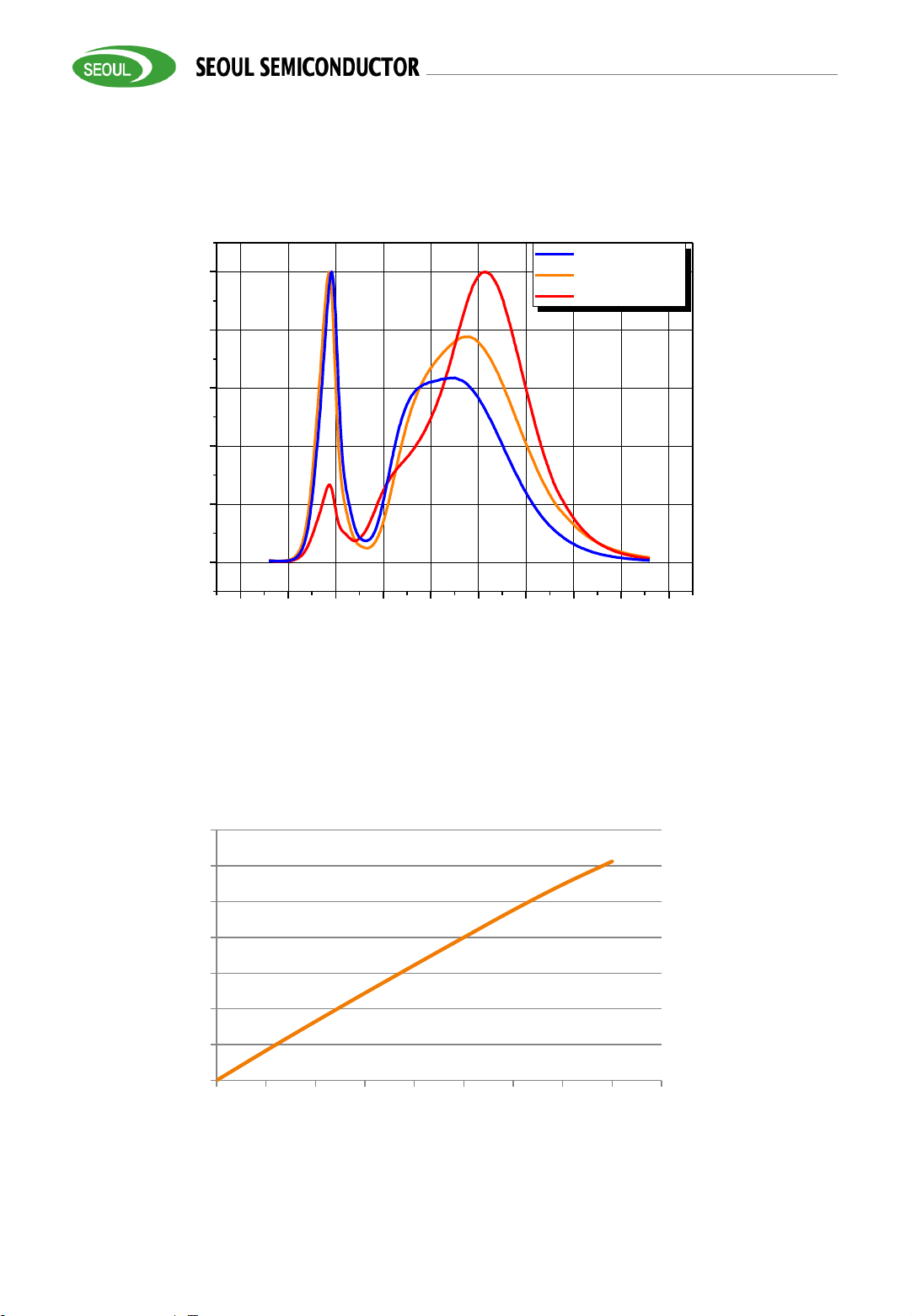
Relative Spectral Distribution
Product Data Sheet
Relative Spectral Distribution vs. Wavelength Characteristic
Driving Current VS Relative Lumen Output; obtained at Ta = 25ºC
0
25
50
75
100
125
150
175
0 100 200 300 400 500 600 700 800 900
350 400 450 500 550 600 650 700 750 800
0
20
40
60
80
100
Relative Radiant Power [%]
Wavelength [nm]
Cool white
Neutral white
Warm white
Relative Lumen Output
【%】
Driving Current【 mA 】
6
Rev0.4.1, December 14, 2017
www.seoulsemicon.com
Product Data Sheet
WICOP 2-Outdoor
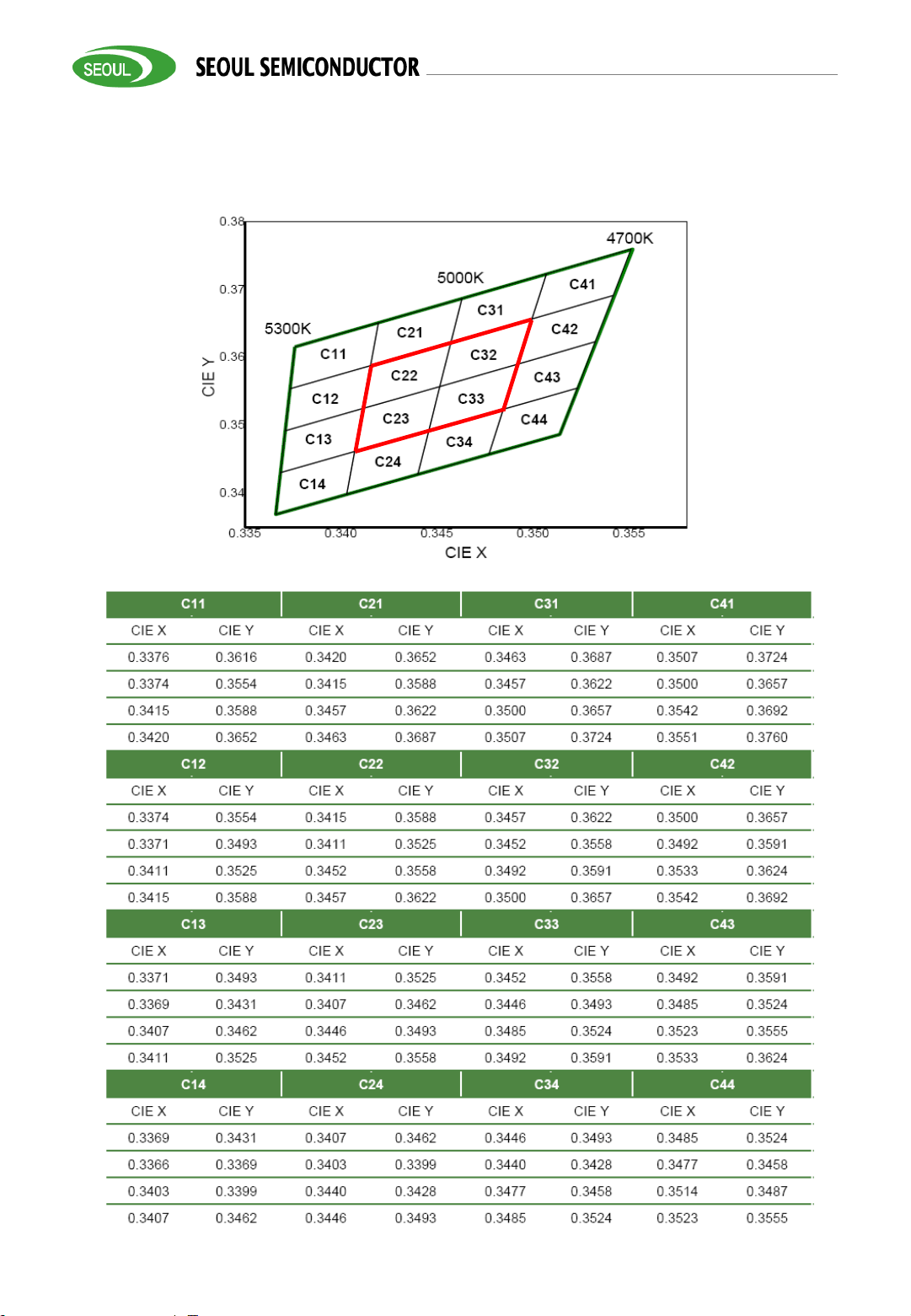
Color Bin Structure
CIE Chromaticity Diagram (Cool White), Tj=85℃, IF=500mA
7
Rev0.4.1, December 14, 2017
www.seoulsemicon.com
Product Data Sheet
WICOP 2-Outdoor
Color Bin Structure
0.36 0.37 0.38 0.39 0.40
0.35
0.36
0.37
0.38
0.39
0.40
0.41
E44
E43
3700K
4000K
4200K
E41
E31
E21
E11
CIE Y
CIE X
E32
E42
E22
E12
E33
E23
E13
E34
E24
E14
CIE Chromaticity Diagram (Neutral White), Tj=85℃, IF=500mA
E11 E21 E31 E41
CIE x CIE y CIE x CIE y CIE x CIE y CIE x CIE y
0.3736 0.3874 0.3804 0.3917 0.3871 0.3959 0.3939 0.4002
0.3720 0.3800 0.3784 0.3841 0.3849 0.3881 0.3914 0.3922
0.3784 0.3841 0.3849 0.3881 0.3914 0.3922 0.3979 0.3962
0.3804 0.3917 0.3871 0.3959 0.3939 0.4002 0.4006 0.4044
E12 E22 E32 E42
CIE x CIE y CIE x CIE y CIE x CIE y CIE x CIE y
0.3720 0.3800 0.3784 0.3841 0.3849 0.3881 0.3914 0.3922
0.3703 0.3726 0.3765 0.3765 0.3828 0.3803 0.3890 0.3842
0.3765 0.3765 0.3828 0.3803 0.3890 0.3842 0.3952 0.3880
0.3784 0.3841 0.3849 0.3881 0.3914 0.3922 0.3979 0.3962
E13 E23 E33 E43
CIE x CIE y CIE x CIE y CIE x CIE y CIE x CIE y
0.3703 0.3726 0.3765 0.3765 0.3828 0.3803 0.3890 0.3842
0.3687 0.3652 0.3746 0.3689 0.3806 0.3725 0.3865 0.3762
0.3746 0.3689 0.3806 0.3725 0.3865 0.3762 0.3925 0.3798
0.3765 0.3765 0.3828 0.3803 0.3890 0.3842 0.3952 0.3880
E14 E24 E34 E44
CIE x CIE y CIE x CIE y CIE x CIE y CIE x CIE y
0.3687 0.3652 0.3746 0.3689 0.3806 0.3725 0.3865 0.3762
0.3670 0.3578 0.3727 0.3613 0.3784 0.3647 0.3841 0.3682
0.3727 0.3613 0.3784 0.3647 0.3841 0.3682 0.3898 0.3716
0.3746 0.3689 0.3806 0.3725 0.3865 0.3762 0.3925 0.3798

8
Rev0.4.1, December 14, 2017
www.seoulsemicon.com
Product Data Sheet
WICOP 2-Outdoor
Color Bin Structure
CIE Chromaticity Diagram (Warm White), Tj=85℃, IF=500mA

9
Rev0.4.1, December 14, 2017
www.seoulsemicon.com
Product Data Sheet
WICOP 2-Outdoor
Naming Rule
S M J Q – L 51 W 68 X X - ET
① ② ③ ④ ⑤ ⑥ ⑦ ⑧ ⑨
① SMJ-Fixed
: SMJ = SSC Module Lighting (Company Standard)
: SEJ = SSC Engine Lighting (Company Standard)
: SKJ = SSC Engine Kit (Company Standard)
: SFJ = SSC Fixture Lighting (Company Standard)
② Q-Application
: P(MR) E(Bulb) D(Down-light) L(Linear) S(Sign) C(Candle) B(Bar)
Q(Outdoor) F(Fan-light) J(SPC or etc.) A(Anti-explosion)
③ L-Lens bar : D = Normal, L = Lens bar , T= Tunable; C= Coating on packages
④ 51-Voltage : 51=51V
⑤ X-PKG TYPE
: Package family (A ~ Z)
W=WICOP
⑥ 68-PKG Qty : 68=68 ea
⑦ D=PKG part no. : A ~ Z (X= D (CRI=80); X=V (CRI=70))
⑧ Type
: type or version of module A ~ Z
30 D 60 D 90 D
Ellipse 36
D
SE
C Rank A D G J M
E Rank B E H K N
F Rank C F I L O
⑨ Reference /
customized
: Reference – XX, customized – customer name

10
Rev0.4.1, December 14, 2017
www.seoulsemicon.com
Product Data Sheet
WICOP 2-Outdoor
Performance Characteristics
30D
60D

11
Rev0.4.1, December 14, 2017
www.seoulsemicon.com
Product Data Sheet
WICOP 2-Outdoor
Performance Characteristics
90D
Ellipse(30 – 60) D

12
Rev0.4.1, December 14, 2017
www.seoulsemicon.com
Product Data Sheet
WICOP 2-Outdoor
Performance Characteristics
SE

13
Rev0.4.1, December 14, 2017
www.seoulsemicon.com
Product Data Sheet
WICOP 2-Outdoor
Mechanical Dimensions
Notes :
(1) All dimensions are in millimeters.
(2) Scale : none
(3) Undefined tolerance is ±0.2mm
X17

14
Rev0.4.1, December 14, 2017
www.seoulsemicon.com
Product Data Sheet
WICOP 2-Outdoor
Application Guide
a).single module application
b). Driver with multi output channels for group application
c). In series all modules for group application
Notes :
(1) If all modules have to be in parallel for a group application , please select the SAME digit of the
module for a group.
160510
D62C058DG0
100001

15
Rev0.4.1, December 14, 2017
www.seoulsemicon.com
Product Data Sheet
WICOP 2-Outdoor
Marking Information
Fig 1. 2D Marking point
Table 1. MP
information
D62 C 05 8 D#0
① ② ③ ④ ⑤
CCT
C
E
F
CRI**
80
70
Vf
D#0
#=G,
or #=H
Flux Bin
0lm A
1000lm B
2000lm C
19000lm T
20000lm U
21000lm V
…
…
① SMT Date (YYMMDD, 6 Digits)
② MP Information (10 Digits)
③ Lot Number (6 Digits)
160510
D62C058D#0
100001
Mixing
Bin
05 5-step

16
Rev0.4.1, December 14, 2017
www.seoulsemicon.com
Product Data Sheet
WICOP 2-Outdoor
Label Information
Notes
(1) It is attached to the bottom right corner of the box.
Model No.
SMJQ-L51W68XX-ET
(1)
IIIII II IIIII III
Rank
D62C058D#0
(2)
IIIII II IIIII III
Type Customized
Quantity
XXX
IIIII II IIIII III
Lot No.
YYMDDXXXXX- XXXXXXX
IIIII II IIIII III
SEOUL SEMICONDUCTOR CO.,LTD.
Notes
(1) Please refer to page 9
(2) Please refer to page 15
(3) It is attached to the top left corner of the box.
Initial of manufacture is refer to the 2D code rule.
YYMDD : Packing Date (Oct. : A, Nov. : B, Dec. : C) X : Initial of Manufacturer
XXXX : Sealing Pack No.
XXXXXXX : SSC Code
TOTAL Quantity
XX
SEOUL SEMICONDUCTOR CO.,LTD.

17
Rev0.4.1, December 14, 2017
www.seoulsemicon.com
Product Data Sheet
WICOP 2-Outdoor
Packaging Specification
Product Data Sheet
Notes
(1) Quantity : 32 pcs/Tray
(2) All dimensions are in millimeters (tolerance : ±0.3)
(3) Scale none
1. Tray information
2. Tray stack and taping
Notes
(1) 10 trays and additional 1 dummy tray up of box
10 trays
Modules
1 dummy tray

18
Rev0.4.1, December 14, 2017
www.seoulsemicon.com
Product Data Sheet
WICOP 2-Outdoor
Packaging Specification
Product Data Sheet
3. Box information & packing
4. Pallet information & packing
Notes
(1) Quantity: 10Tray (120pcs) / Box
(2) Box size: 610*410*215 mm
Notes
(1) Quantity: 1 Pallet = 20 Boxes = 200(20*10) Trays = 6400(200*32) Modules
(2) Pallet size: 1100*1400 mm
Trays
Box
Box Label
Vacumm
bag
Tray Label
Box
Pallet

19
Rev0.4.1, December 14, 2017
www.seoulsemicon.com
Product Data Sheet
WICOP 2-Outdoor
Precaution for Use
(1) Check the appearance of module before wiring/ assembly, DO NOT use the LED cracked or PCB
damaged module.
(2) The module was designed to be driven with DC source, recognize the polarities of the module
was necessity.
(3) It was not SELV module, DO NOT connect the LED directly to main power during wiring.
(4) DO NOT let the LED packages contacted with any hard matters.
(5) There was no current regulator built in module, unevenly load between different parallel modules
may occur due to the modules VFvariance .
(6) Please do not use together with the materials containing Sulfur.
(7)Please do not make any modification on module.

20
Rev0.4.1, December 14, 2017
www.seoulsemicon.com
Product Data Sheet
WICOP 2-Outdoor
Precaution for Use
(11) LEDs are sensitive to Electro-Static Discharge (ESD) and Electrical Over Stress (EOS).
Below is a list of suggestions that Seoul Semiconductor purposes to minimize these effects.
a. ESD (Electro Static Discharge)
Electrostatic discharge (ESD) is the defined as the release of static electricity when two objects
come into contact. While most ESD events are considered harmless, it can be an expensive
problem in many industrial environments during production and storage. The damage from ESD
to an LEDs may cause the product to demonstrate unusual characteristics such as:
- Increase in reverse leakage current lowered turn-on voltage
- Abnormal emissions from the LED at low current
The following recommendations are suggested to help minimize the potential for an ESD event:
One or more recommended work area suggestions:
- Ionizing fan setup
- ESD table/shelf mat made of conductive materials
- ESD safe storage containers
One or more personnel suggestion options:
- Antistatic wrist-strap
- Antistatic material shoes
- Antistatic clothes
Environmental controls
- Humidity control (ESD gets worse in a dry environment)
b. EOS (Electrical Over Stress)
Electrical Over-Stress (EOS) is defined as damage that may occur when an electronic device is
subjected to a current or voltage that is beyond the maximum specification limits of the device.
The effects from an EOS event can be noticed through product performance like:
Changes to the performance of the LED package (If the damage is around the bond pad area and
since the package is completely encapsulated the package may turn on but flicker show severe
performance degradation.)
Changes to the light output of the luminaire from component failure
Components on the board not operating at determined drive power
Failure of performance from entire fixture due to changes in circuit voltage and current across
total circuit causing trickle down failures
It is impossible to predict the failure mode of every LED exposed to electrical overstress as the
failure modes have been investigated to vary, but there are some common signs that will indicate
an EOS event has occurred.
- Damaged may be noticed to the bond wires (appearing similar to a blown fuse).
- Damage to the bond pads located on the emission surface of the LED package
(shadowing can be noticed around the bond pads while viewing through a microscope).
- Anomalies noticed in the encapsulation and phosphor around the bond wires.
- This damage usually appears due to the thermal stress produced during the EOS event.
c. To help minimize the damage from an EOS event Seoul Semiconductor recommends utilizing
- qualified LED driver with no big over shoot out put
- Isolated driver that to prevent harmful peaks passed to module.
- A current limiting device

21
Rev0.4.1, December 14, 2017
www.seoulsemicon.com
Product Data Sheet
WICOP 2-Outdoor
Storage before use
(1) Do not impact or place pressure on this product because even a small amount of pressure can
damage the packages.
(2) When storing devices for a long period of time before usage, please following these guidelines:
* The devices should be stored in the anti-static bag that it was shipped in from
Seoul-Semiconductor with opening.
* If the anti-static bag has been opened, re-seal preventing air and moisture from being present
in the bag.

22
Rev0.4.1, December 14, 2017
www.seoulsemicon.com
Product Data Sheet
WICOP 2-Outdoor
Company Information
Published by
Seoul Semiconductor © 2013 All Rights Reserved.
Company Information
Seoul Semiconductor (SeoulSemicon.com) manufacturers and packages a wide selection of light
emitting diodes (LEDs) for the automotive, general illumination/lighting, appliance, signage and back
lighting markets. The company is the world’s fifth largest LED supplier, holding more than 10,000
patents globally, while offering a wide range of LED technology and production capacity in areas such
as “nPola”, deep UV LEDs, "Acrich", the world’s first commercially produced AC LED, and "Acrich
MJT - Multi-Junction Technology" a proprietary family of high-voltage LEDs. The company’s broad
product portfolio includes a wide array of package and device choices such as Acrich, high-brightness
LEDs, mid-power LEDs, side-view LEDs, through-hole type LED lamps, custom displays, and sensors.
The company is vertically integrated from epitaxial growth and chip manufacture in it’s fully owned
subsidiary, Seoul Viosys, through packaged LEDs and LED modules in three Seoul Semiconductor
manufacturing facilities. Seoul Viosys also manufactures a wide range of unique deep-UV
wavelength devices.
Legal Disclaimer
Information in this document is provided in connection with Seoul Semiconductor products. With
respect to any examples or hints given herein, any typical values stated herein and/or any information
regarding the application of the device, Seoul Semiconductor hereby disclaims any and all warranties
and liabilities of any kind, including without limitation, warranties of non-infringement of intellectual
property rights of any third party. The appearance and specifications of the product can be changed
to improve the quality and/or performance without notice.
 Loading...