

Technical Data Sheet
Z-Power LED X10490Z-Power LED X10490
Specification
C9WT728
SSC
CUSTOMER
ApprovalApprovalDrawn
Rev. 03
Rev. 03
June 2009
June 2009
www.acriche.com
www.acriche.com
SSC-QP-7-07-24 (Rev.00)

Technical Data Sheet
Z-Power LED X10490Z-Power LED X10490
1. Description
2. Absolute Maximum Ratings
3. Electro-Optical Characteristics
4. Optical characteristics
5. Reliability Test
CONTENTS
6. Color & Binning
7. Bin Code Description
8. Outline Dimension
9. Reel Structure
10. Packing
11. Soldering
12. Precaution for use
13. Handling of Silicone Resin LEDs
Rev. 03
Rev. 03
June 2009
June 2009
www.acriche.com
www.acriche.com
SSC-QP-7-07-24 (Rev.00)
Technical Data Sheet
Z-Power LED X10490Z-Power LED X10490
C9WT728
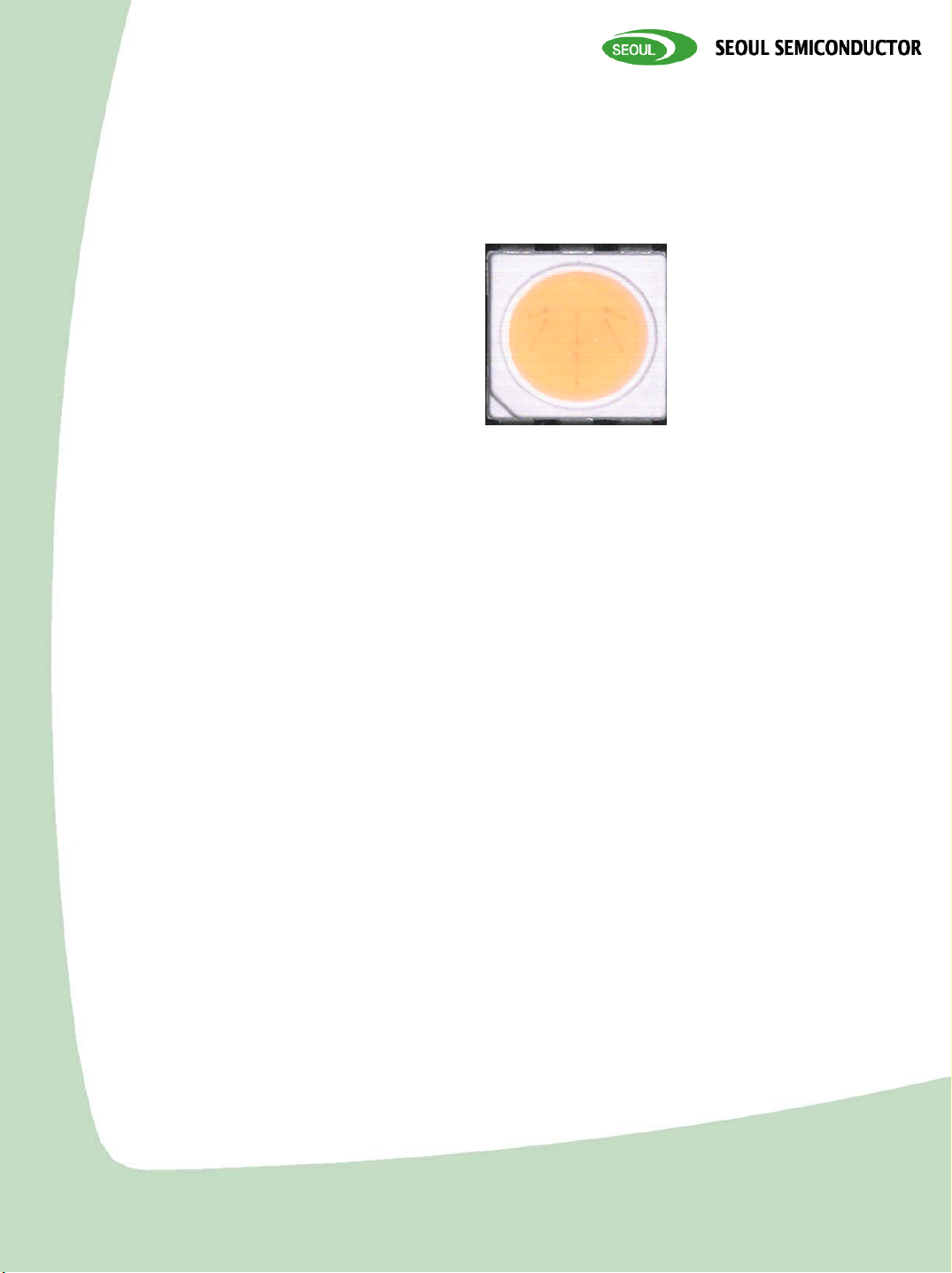
1. Description
TOP VIEW LED is designed for
high current operation and
high flux output applications.
Furthermore, its thermal management characteristic
is better than other LED solutions by package SMD
design and good thermal emission material.
According to these advantages, it enables to apply
various lighting applications and design solution,
automotive lighting etc.
C9WT728
Features
• White & Warm colored
SMT package.
•High CRI PKG
• Pb-free Reflow Soldering
Application
• Suitable for all SMT
assembly methods ;
Suitable for all soldering
methods
• RoHS Compliant
•MSL LEVEL 2a
Applications
• Interior lighting
• General lighting
• Indoor and out door
displays
• Architectural / Decorative
lighting
Rev. 03
Rev. 03
June 2009
June 2009
www.acriche.com
www.acriche.com
SSC-QP-7-07-24 (Rev.00)
Technical Data Sheet
Z-Power LED X10490Z-Power LED X10490
2. Absolute maximum ratings
UnitValueSymbolParameter
Power Dissipation
Forward Current
Peak Forward Current
(Per die)
Reverse Voltage (per die)
Operating Temperature
Storage Temperature
*1 Care is to be taken that power dissipation does not exceed the absolute maximum rating of the product.
*2 IFM was measured at TW≤ 1msec of pulse width and D ≤ 1/10 of duty ratio.
FM
d
F
*2
R
opr
stg
mW324P
mA90I
mA100I
V5V
ºC-40 ~ +85T
ºC-40 ~ +100T
3. Electric & Optical characteristics
UnitMaxTypMinConditionSymbolParameter
Forward Voltage (per die)
Reverse Current (per die)
Luminance Intensity
*1
[4,700 ~ 7,000 K]
Luminance Intensity
*1
[2,600 ~ 4,700 K ]
V
F
I
R
I
V
I
V
IF=20mA
VR=5V
IF=60mA
IF=60mA
10--
V3.63.33.0
µA
cd-4.84.0
cd-4.54.0
Luminance Flux
[CIE X = 0.31, Y = 0.31]
Optical Efficiency
Viewing Angle
*2
Φ
V
Ŋ
elc
2
θ
½
RaColor Rendering Index
*1. The luminous intensity IV was measured at the peak of the spatial pattern which may not be aligned
with the mechanical axis of the LED package. Luminous Intensity Measurement allowance is ±10%
*2. 2θ½ is the off-axis where the luminous intensity is 1/2 of the peak intensity.
[Note] All measurements were made under the standardized environment of SSC.
IF=60mA
IF=60mA
IF=60mA
IF=60mA
95
www.
www.
lm/W-73-
deg-120-
June 2009
June 2009
acriche
acriche
SSC-QP-7-07-24 (Rev.00)
lm-14.5-
K7,0002,600CCTColor Temperature
Rev. 03
Rev. 03
.com
.com
Technical Data Sheet
Z-Power LED X10490Z-Power LED X10490
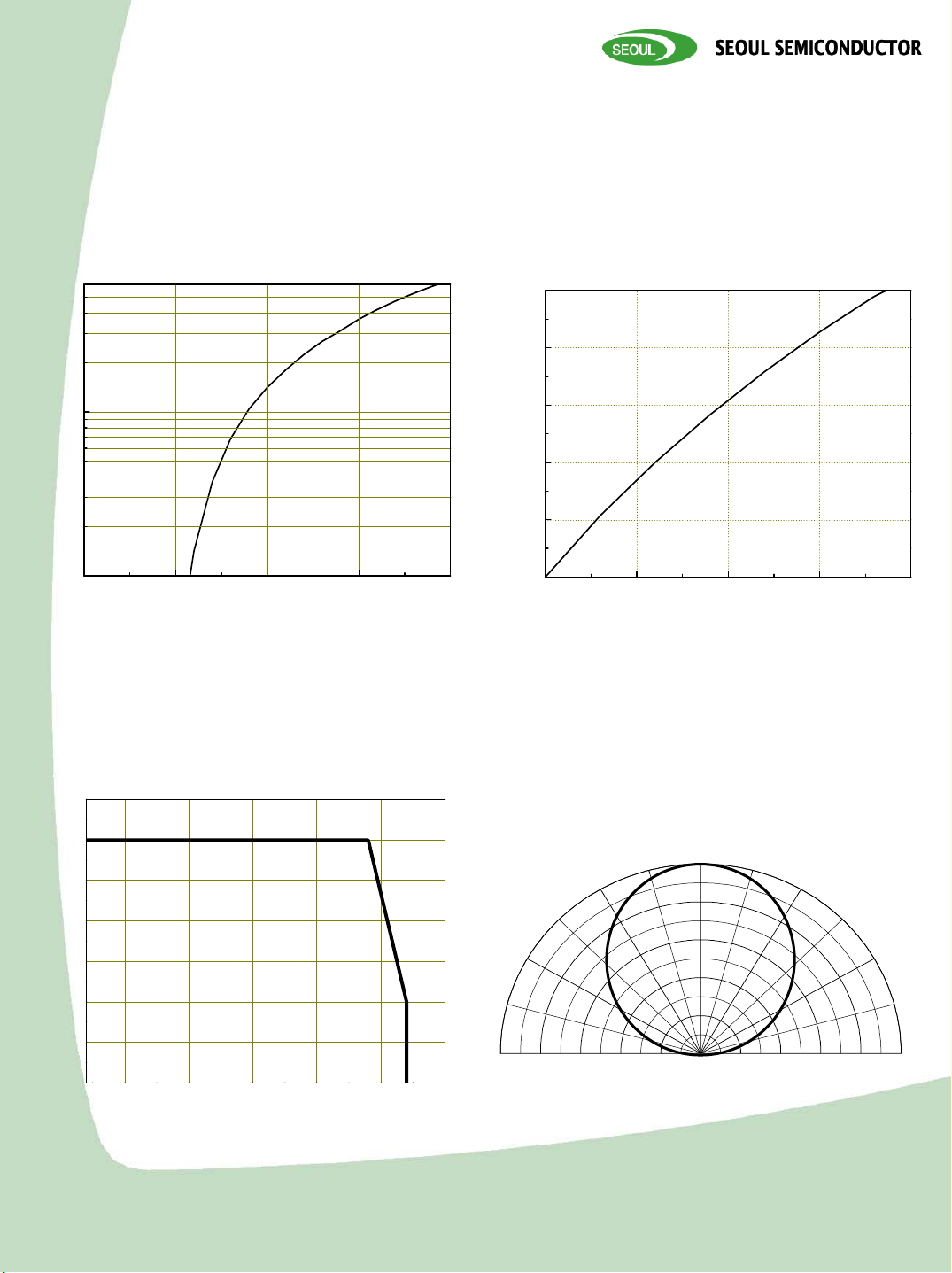
4. Optical characteristics
Forward Voltage
vs. Forward Current (Per die)
10
Forward Current [mA]
1
2.0 2.5 3.0 3.5 4.0
Forward Voltage[V]
Forward Current
vs. Relative Luminous Intensity
2.5
2.0
1.5
1.0
Relative luminouce Flux [lm]
0.5
0.0
0 50 100 150 200
Forward Current IF[mA]
Ambient Temperature
vs. Maximum Forward Current (per die)
35
30
25
[mA]
F
20
15
10
Forward Current I
5
0
-25 0 25 50 75 100
Ambient temperature Ta(OC)
-90
-60
Directivity
-30
0
30
60
90
Rev. 03
Rev. 03
June 2009
June 2009
www.
www.
acriche
acriche
.com
.com
SSC-QP-7-07-24 (Rev.00)
Technical Data Sheet
Z-Power LED X10490Z-Power LED X10490
5. Reliability Test
Thermal Shock
High Temperature
Storage
High Temp. High
Humidity Storage
Low Temperature
Storage
Operating
Endurance Test
High Temperature
High Humidity Life
Test
High Temperature
Life Test
Low Temperature
Life Test
ESD(HBM)
EIAJ
ED-4701
EIAJ
ED-4701
EIAJ
ED-4701
EIAJ
ED-4701
Internal
Reference
Internal
Reference
Internal
Reference
Internal
Reference
MIL-STD-
883D
Test ConditionsReferenceItem
T
=-40oC(30min) ~
a
o
100
C(30min)
=100oC
a
=60oC, RH=90%
a
=-40oC
a
=25oC, IF=60mA
a
T
=60oC, RH=90%, IF=60mA
a
=85oC, IF=60mA
a
=-40oC, IF=60mA
a
Duration /
Cycle
1000
Cycle
500
Hours
Number
of
Damaged
0/22
0/221000 HoursT
0/221000 HoursT
0/221000 HoursT
0/221000 HoursT
0/22
0/221000 HoursT
0/221000 HoursT
0/223 Time1KV at 1.5kΩ; 100pF
□ CRITERIA FOR JUDGING THE DAMAGE
Forward Voltage
Reverse Current
Luminous Intensity
Note : *1 USL : Upper Standard Level
*2 LSL : Lower Standard Level
V
F
R
I
V
ConditionSymbolItem
I
=60mA
F
(20mA per die)
=5VI
R
I
=60mA
F
(20mA per die)
Criteria for Judgment
MAXMIN
*1
USL
USL
www.
www.
*1
acriche
acriche
LSL
*2
-
-V
× 0.5
SSC-QP-7-07-24 (Rev.00)
× 1.2
× 2.0
-
Rev. 03
Rev. 03
June 2009
June 2009
.com
.com

Technical Data Sheet
Z-Power LED X10490Z-Power LED X10490
6. Color & Binning
0.9
520
525
530
0.8
515
510
0.7
505
0.6
500
0.5
0.4
495
CIE (y)
0.3
490
535
540
545
550
555
560
565
570
575
580
585
590
595
600
610
620
630
830
0.2
0.1
485
480
475
470
460
0.0
0.0 0.1 0.2 0.3 0.4 0.5 0.6 0.7 0.8
C I E (x)
Rev. 03
Rev. 03
June 2009
June 2009
www.
www.
SSC-QP-7-07-24 (Rev.00)
acriche
acriche
.com
.com

Technical Data Sheet
Z-Power LED X10490Z-Power LED X10490
6. Color & Binning
0.44
0.42
0.40
0.38
0.36
CIE Y
0.34
0.32
0.30
ENERGY STAR RANK
(7000K~2600K)
4700K
5000K
6500K
7000K
5600K
6000K
A2
A1
X
5300K
B2
B1
Y
C3
C1
C4
C2
Z
4200K
4500K
D1
D2
D3
D4
4000K
E1
E2
3700K
E3
E4
3500K
F1
F2
F3
F4
3200K
G2
3000K
G1
G4
2900K
G3
H2
2700K
H1
H4
2600K
H3
0.28
0.28 0.30 0.32 0.34 0.36 0.38 0.40 0.42 0.44 0.46 0.48
CIE X
www.
www.
SSC-QP-7-07-24 (Rev.00)
Rev. 03
Rev. 03
June 2009
June 2009
acriche
acriche
.com
.com

Technical Data Sheet
Z-Power LED X10490Z-Power LED X10490
6. Color & Binning
● COLOR RANK
<IF=60mA, Ta=25℃>
6000 ~ 5600 K7000 ~ 6500 K
5600 ~ 5300 K6500 ~ 6000 K
B2B1A2A1
CIE YCIE XCIE YCIE XCIE YCIE XCIE YCIE X
0.35390.32920.34620.32070.33930.31170.33040.3028
0.33060.32940.32430.32220.31870.31450.31130.3068
0.33690.33660.33060.32940.32610.32210.31870.3145
0.36160.33760.35390.32920.34810.32050.33930.3117
5000 ~ 4700 K5300 ~ 5000 K
C4C3C2C1
CIE YCIE XCIE YCIE XCIE YCIE XCIE YCIE X
0.35540.34510.36870.34630.3490.33710.36160.3376
0.34280.3440.35540.34510.33690.33660.3490.3371
0.34870.35150.3620.35330.34280.3440.35540.3451
0.3620.35330.3760.35510.35540.34510.36870.3463
5300 ~ 4700 K6000 ~ 5300 K7000 ~ 6000 K
ZYX
CIE YCIE XCIE YCIE XCIE YCIE X
0.31050.32340.2940.3104
0.33660.32430.32220.31130.3068
0.33690.33660.32610.3221
0.32580.33650.31050.3234
0.32580.3365
0.3369
0.34870.3515
0.340.35
● A~C, X~Z -> CCT 4700 ~ 7000 K
* Measurement Uncertainty of the Color Coordinates : ± 0.01
Rev. 03
Rev. 03
June 2009
June 2009
www.
www.
SSC-QP-7-07-24 (Rev.00)
acriche
acriche
.com
.com

Technical Data Sheet
Z-Power LED X10490Z-Power LED X10490
6. Color & Binning
● COLOR RANK
<IF=60mA, Ta=25℃>
4500 ~ 4200 K4700 ~ 4500 K
D4D3D2D1
CIE YCIE XCIE YCIE XCIE YCIE XCIE YCIE X
0.36590.36150.38040.36410.35970.35290.37360.3548
0.35210.3590.36590.36150.34650.35120.35970.3529
0.35780.3670.37220.37020.35210.3590.36590.3615
0.37220.37020.38740.37360.36590.36150.38040.3641
4000 ~ 3700 k4200 ~4000 K
E4E3E2E1
CIE YCIE XCIE YCIE XCIE YCIE XCIE YCIE X
0.37980.38250.39580.38690.37220.37020.38740.3736
0.36460.37830.37980.38250.35780.3670.37220.3702
0.37160.38980.38750.3950.36460.37830.37980.3825
0.38750.3950.40440.40060.37980.38250.39580.3869
3500 ~ 3200 K3700 ~ 3500 K
F4F3F2F1
CIE YCIE XCIE YCIE XCIE YCIE XCIE YCIE X
0.39160.4080.40890.41460.38480.39410.40150.3996
0.37510.40170.39160.4080.3690.38890.38480.3941
0.38140.41470.39840.42210.37510.40170.39160.408
0.39840.42210.41650.42990.39160.4080.40890.4146
3000 ~ 2900 k3200 ~3000 K
G4G3G2G1
CIE YCIE XCIE YCIE XCIE YCIE XCIE YCIE X
0.40280.43420.42120.4430.39840.42210.41650.4299
0.38530.42590.40280.43420.38140.41470.39840.4221
0.38930.43730.40710.44650.38530.42590.40280.4342
0.40710.44650.4260.45620.40280.43420.42120.443
2700 ~ 2600 K2900 ~ 2700 K
H4H3H2H1
CIE YCIE XCIE YCIE XCIE YCIE XCIE YCIE X
0.40990.45820.42890.46870.40710.44650.4260.4562
0.39190.44830.40990.45820.38930.43730.40710.4465
0.39440.45930.41260.470.39190.44830.40990.4582
0.41260.470.43190.48130.40990.45820.42890.4687
● D~H -> CCT 2600 ~ 4700 K
* Measurement Uncertainty of the Color Coordinates : ± 0.01
Rev. 03
Rev. 03
June 2009
June 2009
www.
www.
SSC-QP-7-07-24 (Rev.00)
acriche
acriche
.com
.com

Technical Data Sheet
Z-Power LED X10490Z-Power LED X10490
7. Bin Code Description
Bin Code
4,700
K ~ 7,000K
4,700
K ~ 7,000K
Forward Voltage [V]Color RankLuminous Intensity [mcd]
Z1A1M0
Luminous Intensity [mcd]
= 60mA
@ I
F
Max.Min.RANK
4,5004,000M0
5,0004,500M5
5,5005,000N0
6,0005,500N5
6,5006,000P0
Color Rank
= 60mA
@ I
F
Z
2,600
K ~ 4,700K
2,600
K ~ 4,700K
Color Rank
@ I
= 60mA
F
Average for Total
Forward Voltage [V]
A2A1
B2B1
C2C1
C4C3
YX
D2D1
D4D3
E2E1
E4E3
@ IF = 60mA
Max.Min.RANK
3.13.0Z1
3.23.1Z2
3.33.2Z3
3.453.3A1
3.63.45A2
F2F1
F4F3
G2G1
G4G3
H2H1
H4H3
Rev. 03
Rev. 03
June 2009
June 2009
www.
www.
SSC-QP-7-07-24 (Rev.00)
acriche
acriche
.com
.com

Technical Data Sheet
Z-Power LED X10490Z-Power LED X10490
8.Outline Dimension
Package Outlines
W1
Package
Marking
(Cathode)
Circuit Diagram
White Anode
6
5
6
1
W3W2
45
23
4
Right ViewFront View
R ecom m ended
Solder P ad
Rear View
( Tolerance: ±0.2, Unit: mm )
1
White Cathode
* MATERIALS
2
3
MATERIALSPARTS
Heat-Resistant PolymerPackage
Silicone ResinEncapsulating Resin
Ag Plating Copper AlloyElectrodes
Rev. 03
Rev. 03
June 2009
June 2009
www.
www.
SSC-QP-7-07-24 (Rev.00)
acriche
acriche
.com
.com

Technical Data Sheet
Z-Power LED X10490Z-Power LED X10490
9. Reel Structure
?
1
.
5
+
0
.
1
,
0
4±0.1
2±0.05
1.75±0.15.5±0.05
12.0±0.2
(4.75)
0.3-0.05
5.7±0.1
8±0.1
13
180
5.3
2
2.1±0.1
Package
Marking
15.4±1.0
13±0.3
60
22
( Tolerance: ±0.2, Unit: mm )
1)Quantity : 1,000pcs/Reel
2)Cumulative Tolerance : Cumulative Tolerance/10 pitches to be ±0.2mm
3)Adhesion Strength of Cover Tape : Adhesion strength to be 0.1-0.7N when the cover tape is
turned off from the carrier tape at the angle of 10 to the carrier tape
4)Package : P/N, Manufacturing data Code No. and quantity to be indicated on a damp proof
Package
Rev. 03
Rev. 03
June 2009
June 2009
www.
www.
acriche
acriche
SSC-QP-7-07-24 (Rev.00)
.com
.com

Technical Data Sheet
Z-Power LED X10490Z-Power LED X10490
10. Packing
Reel
QUANTITY : XXXX
LOT NUMBER : XXXXXXXXXX
PART NUMBER :
SEOUL SEMICONDUCTOR CO., LTD.
Aluminum Vinyl Bag
HUMIDITY INDICATOR
DESI PAK
QUANTITY : XXXX
LOT NUMBER : XXXXXXXXXX
PART NUMBER :
SEOUL SEMICONDUCTOR CO., LTD.
Outer Box Structure
Material : Paper(SW3B(B))
TYPE
7inch
SIDE
1
QUANTITY : XXXX
LOT NUMBER : XXXXXXXXXX
PART NUMBER :
SEOUL SEMICONDUCTOR CO., LTD.
SIZE (mm)
a
220245
245 220
c
b
102
142
TUV
Acriche
Semiconductor EcoLight
RoHS
a
c
MADE IN KOREA
1
b
Rev. 03
Rev. 03
June 2009
June 2009
www.
www.
acriche
acriche
.com
.com
SSC-QP-7-07-24 (Rev.00)

Technical Data Sheet
Z-Power LED X10490Z-Power LED X10490
11. Soldering
(1) Lead Solder
Lead Solder
(2) Lead-Free Solder
Lead Free Solder
Lead Solder
o
120~150℃Pre-heat
120 sec. Max.Pre-heat time
240℃ Max.Peak-Temperature
10 sec. Max.Soldering time Condition
150~200℃Pre-heat
120 sec. Max.Pre-heat time
260℃ Max.Peak-Temperature
10 sec. Max.Soldering time Condition
2.5~5 C / sec.
o
1~5 C / sec.
2.5~5 C / sec.
Pre-heating
120~150 C
120sec. Max.
Pre-heating
150~200 C
120sec. Max.
o
Lead-free Solder
o
1~5 C / sec.
o
60sec. Max.
Above 200 C
60sec. Max.
Above 220 C
o
o
240 C Max.
10 sec. Max.
o
o
260 C Max.
10 sec. Max.
(3) Hand Soldering conditions
Do not exceed 4 seconds at maximum 315ºC under soldering iron.
(4) The encapsulated material of the LEDs is silicone.
Precautions should be taken to avoid the strong pressure on the encapsulated part.
So when using the chip mounter,
the picking up nozzle that does not affect the silicone resign should be used.
[Note] In case that the soldered products are reused in soldering process, we don’t guarantee the products.
Rev. 03
Rev. 03
June 2009
June 2009
www.
www.
acriche
acriche
.com
.com
SSC-QP-7-07-24 (Rev.00)

Technical Data Sheet
Z-Power LED X10490Z-Power LED X10490
12. Precaution for use
1) Storage
In order to avoid the absorption of moisture, it is recommended to store in a dry box (or a desiccator)
with a desiccant. Otherwise, to store them in the following environment is recommended.
Temperature : 5ºC ~30ºC Humidity : maximum 65%RH
2) Attention after open.
LED is correspond to SMD, when LED be soldered dip, interfacial separation may affect the light
transmission efficiency, causing the light intensity to drop. Attention in followed;
a. After opened and mounted the soldering shall be quickly.
b. Keeping of a fraction
Temperature : 5 ~ 40ºC Humidity : less than 30%
3) In the case of more than 4 week passed after opening or change color of indicator on desiccant,
components shall be dried 10-12hr. at 60±5ºC.
4) Any mechanical force or any excess vibration shall not be accepted to apply during cooling process to
normal temperature after soldering.
5) Quick cooling shall be avoided.
6) Components shall not be mounted on warped direction of PCB.
7) Anti radioactive ray design is not considered for the products.
8) This device should not be used in any type of fluid such as water, oil, organic solvent etc.
When washing is required, IPA should be used.
9) When the LEDs are illuminating, operating current should be decided after considering the ambient
maximum temperature.
10) LEDs must be stored to maintain a clean atmosphere. If the LEDs are stored for 3 months or more
after being shipped from SSC, a sealed container with a nitrogen atmosphere should be used for storage.
11) The LEDs must be soldered within seven days after opening the moisture-proof packing.
12) Repack unused products with anti-moisture packing, fold to close any opening and then store
in a dry place.
13) The appearance and specifications of the product may be modified for improvement without notice.
Rev. 03
Rev. 03
June 2009
June 2009
www.
www.
acriche
acriche
.com
.com
SSC-QP-7-07-24 (Rev.00)

Technical Data Sheet
Z-Power LED X10490Z-Power LED X10490
13. Handling of Silicone Resin LEDs
1) During processing, mechanical stress on the surface should be minimized as much as possible.
Sharp objects of all types should not be used to pierce the sealing compound.
2) In general, LEDs should only be handled from the side. By the way, this also applies to LEDs
without a silicone sealant, since the surface can also become scratched.
3) When populating boards in SMT production, there are basically no restrictions regarding the form of the
pick and place nozzle, except that mechanical pressure on the surface of the resin must be prevented.
This is assured by choosing a pick and place nozzle which is larger than the LED’s reflector area.
4) Silicone differs from materials conventionally used for the manufacturing of LEDs. These conditions
must be considered during the handling of such devices. Compared to standard encapsulants, silicone is
generally softer, and the surface is more likely to attract dust.
As mentioned previously, the increased sensitivity to dust requires special care during processing.
In cases where a minimal level of dirt and dust particles cannot be guaranteed, a suitable cleaning solution
must be applied to the surface after the
soldering of components.
5) SSC suggests using isopropyl alcohol for cleaning. In case other solvents are used, it
must be assured that these solvents do not dissolve the package or resin.
Ultrasonic cleaning is not recommended. Ultrasonic cleaning may cause damage to the LED.
6) Please do not mold this product into another resin (epoxy, urethane, etc) and
do not handle this product with acid or sulfur material in sealed space.
Rev. 03
Rev. 03
June 2009
June 2009
www.
www.
SSC-QP-7-07-24 (Rev.00)
acriche
acriche
.com
.com
 Loading...