

Seon Mobile Surveillance Explorer Premier Mobile Digital Video Recording,Explorer Premier System Installation And Quick Start Manual
Explorer® Premier Mobile Digital Video Recording (DVR) System
Installation and Quick Start Guide
The Explorer Premier DVR is installed with a mounting plate, a security front cover with lock set, and a cable cover which ensures that the
back panel connections are tamper proof. The cable cover has three cable grommets to allow for wiring to be inserted.
To mount the DVR in a suspended horizontal mount under a seat or on a shelf, use the optional mounting bracket.
Check that you have all the system components and inspect the units for any scratches or damage.
You will need these materials to complete the installation:
• DVR keys for securing the removable hard drives
• Front cover keys for the security front cover
• Key or security screw driver (Phillips screw driver)
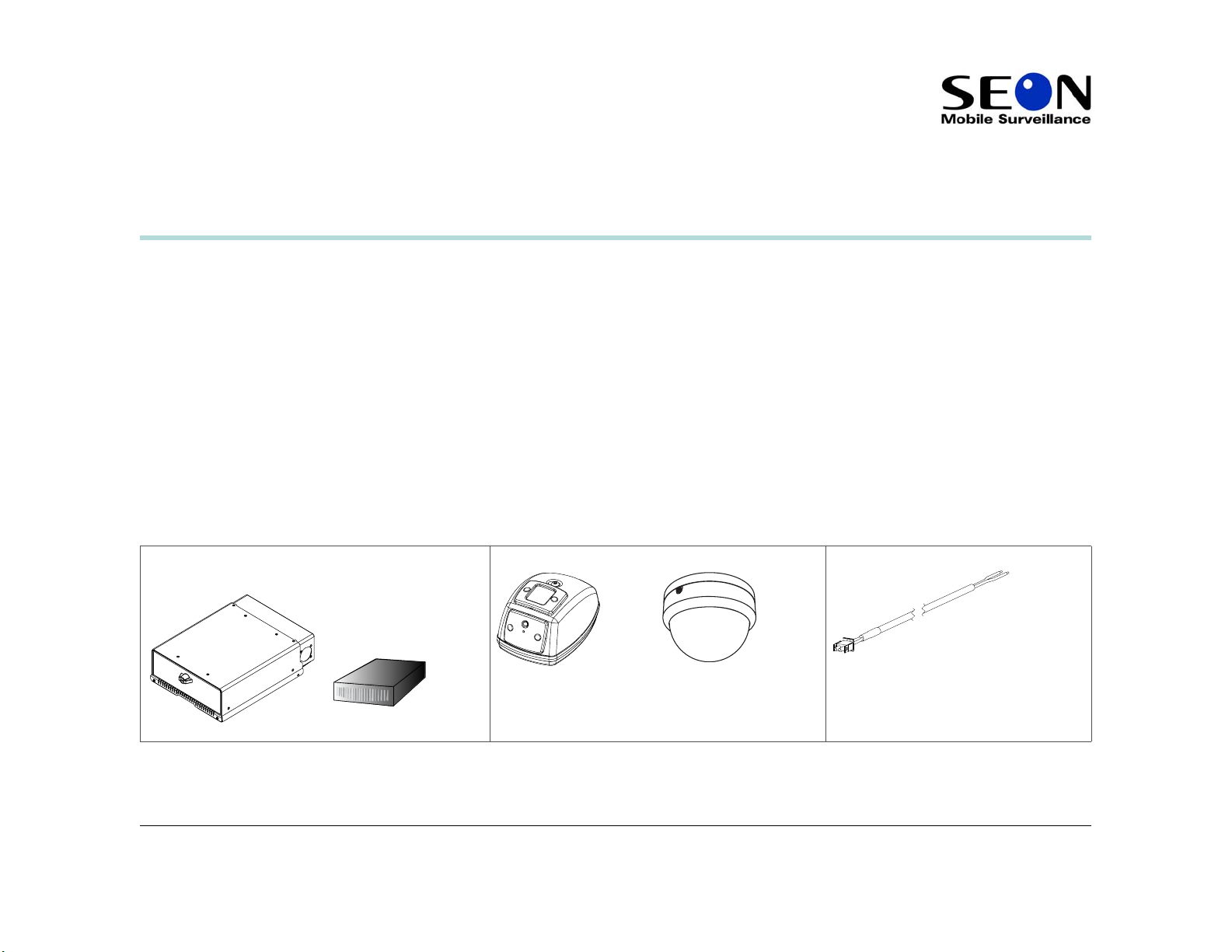
Package Contents (typical) for Premier
The contents of a typical installation package are listed below. The actual contents of your installation package may vary.
Explorer Premier DVR with security front cover and cable
cover, media cartridge hard drive
700-0047 R002
*700-0047*
Cameras × 8 Ignition harness wire
1
Quick Insta llation Guide
Power input harness with in-line fuses SA external microphone (optional) IR Illuminator (optional)
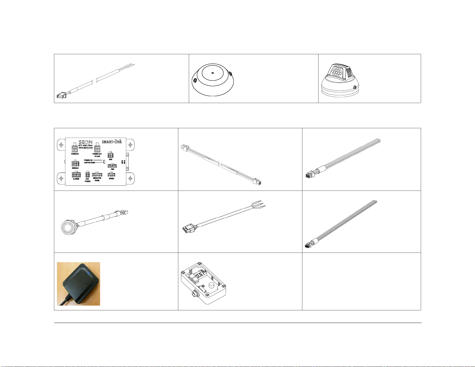
Premier Plus components
Smart-Link™ module for signal interfaces Smart-Link-to-DVR connection harness (identical
connectors)
Diagnostic indicator/alarm button (extension wiring
not shown)
GPS receiver (optional) Inertia sensor (optional)
Speed cable Alarm input harness
Signal harness
2
700-0047
R002

Explorer® Premier
Typical Plus System Setup
Quick Installation Guide
Peripherals
Supports Eight Cameras
i.e. Inertia Sensor
*2
4 wires
*1
4 wires
2 wires
Remote Microphone
IR Illuminators
GPS Receiver
Diagnostic Indicator/
Alarm Button
Auxiliary Power
i.e. Smart-Reach™ Mobile (Wi-Fi)
*1 For better speed tracking, Seon recommends using a GPS receiver.
*2 If camera 1 and/or camera 2 are connected to only cameras, then the
Premier can support 2 remote microphones.
POWER IN
SIGNALS
ALARMS
POWER
AUX.
POWER
AUDIO1 AUDIO2
SMART
LINK™
Smart-Link™
POWER OUT
TO DVR
INDICATOR
PANEL
Seon System
AUX
POWER1
GPS
CAN
SPEED
AUDIO OUT VIDEO OUT
AUX
POWER2
Explorer Premier DVR Rear Panel
GPS
DB-9
Vehicle Electrical Interface
CAMERA8CAMERA7CAMERA6CAMERA5CAMERA4CAMERA3CAMERA2CAMERA1
CONTROL
LAN2 LAN3
CONSTANT POWER
10A
2 wires
3 wires
8 wires
5 wires
2 wires
Vehicle + 12V (red)
Vehicle Ground (black)
SPEED
Red - Call Seon if using hall sensor
Green - Speed sensor high
Black - Speed sensor low
ALARMS
Alarm 1 (orange)
Alarm 2 (blue)
Alarm 3 (violet)
Alarm 4 (gray)
Alarm 1-4 Ground (black)
4 wires
SIGNALS
Left Turn (black)
Inertia Sensor (green)
Brake Signal (red)
Warning (brown)
Right Turn (white)
SWITCHED POWER
1A
Vehicle Switched + 12V (yellow)
Vehicle Ground (black)
Figure 1
Typical Plus System
700-0047 R002 3
Quick Insta llation Guide
Installation
The DVR typically ships with the security front cover and the cable cover on.
Horizontal Installation with the Mounting Plate
To install the Premier DVR:
1 Select an appropriate mounting location. For the dimensions and locations of the mounting holes, see Figure 11.
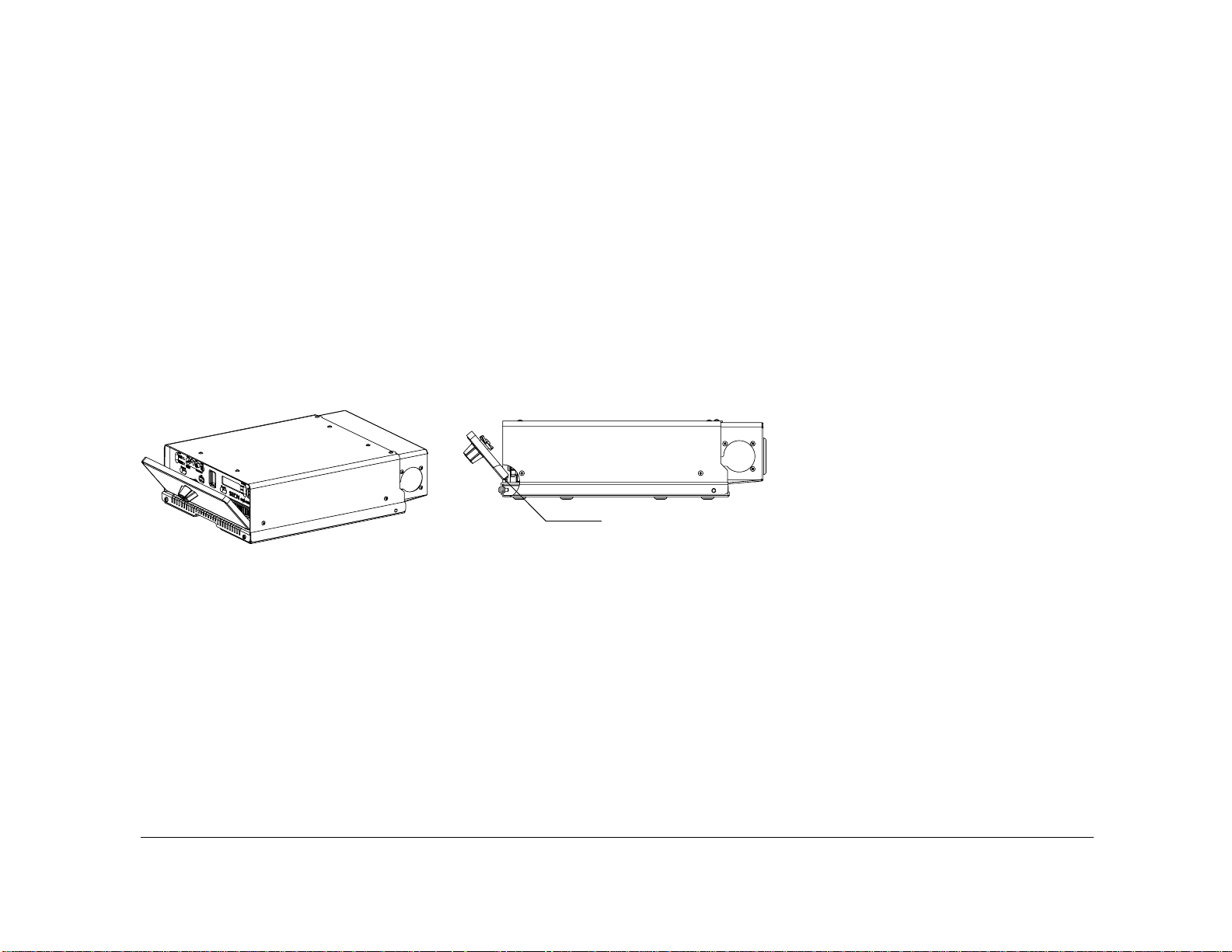
2 Unlock the door lock and remove the security front cover from the unit to access the front panel.
The front cover key is required to unlock the door latch on the front cover. To unlock and remove the front cover, insert the front cover key
and turn clockwise. Turn the door latch counterclockwise. Remove the security front cover from the unit. The front cover sits on two pins.
See Figure 2.
Pin × 2
Figure 2
Security front cover with locking door latch
3 Ensure the two hard drives are installed in the DVR and locked in place.
4 Remove the cable cover from the unit. Determine where the wiring and camera cables will enter the unit: on the left side, right side or
back.
The secure cable cover ensures that the back panel connections are tamper proof once the DVR is completely installed. Three cable
4
700-0047
R002
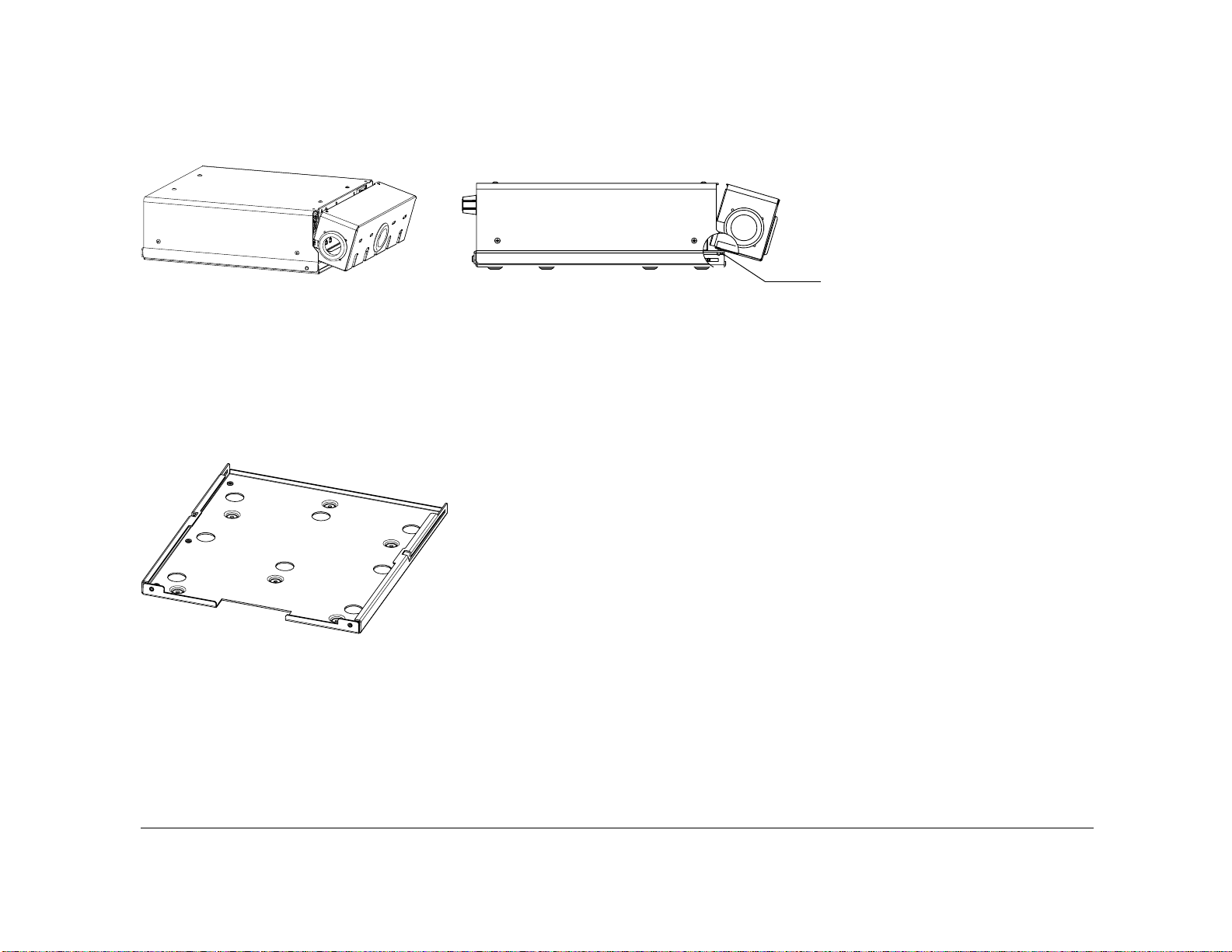
Quick Installation Guide
grommets on the cable cover allow the wiring to be inserted from different sides. The cable cover sits on two pins. See Figure 3.
Pin × 2
Figure 3
Cable cover removed from DVR
5 Remove the necessary knockout (s), insert plugs and cable grommets.
6 Use the mounting plate to mark the desired position of the DVR and drill the 6 mounting holes. Make sure the front flange is facing
forward. This is where the DVR is attached to the mounting plate with security Torx screws.
7 Fasten the mounting plate to the mounting surface using the six #10 × ¾ screws provided.
Figure 4
Mounting plate front view. sliding the DVR on, attaching security Torx screws
8 Slide the DVR onto the rails of the mounting plate. See Figure 4. (Only the rails are shown to highlight the detailed area.)
700-0047 R002 5
 Loading...