

Seon Mobile Surveillance Explorer EX4 Plus 35 System Installation And User Manual

Explorer™ EX4 Plus 35
Mobile Digit al Video
Recording (DVR) System
Installation and User’s Guide
Manual Type
*700-0058*
Document part number 700-0058 R001


Seon Design® Inc.
Seon Design Inc. is a specialist in the design and manufacture of video surveillance systems for mobile applications. Seon has
been the preferred solutions provider for the pupil transportation industry since 1999. Today, we are proud that our success in
this area has made us the leading manufacturer of mobile video surveillance systems in North America.
Contact Information
Seon Design Inc.
Unit 111, 3B Burbidge Street
Coquitlam, BC
Canada V3K 7B2
Telephone 604.941.0880
Toll Free Telephone 1.877.630.7366
Fax 604.941.0870
Toll Free Fax 1.866.664.3677
Email sales@seon.com
Web site www .seon.com
Seon Design Inc. Trademarks
Seon Design Inc. holds the following trademarks:
Explorer™ is a registered trademark of Seon Design Inc.
“Seon Design” is a registered trademark of Seon Design Inc.
The Seon logo ( ) is a registered trademark of Seon Design Inc.
In this User Manual there are references to trademarks, registered trademarks, and product names not owned by Seon Design
Inc. that are the property of their respective owners. They are used in this User Manual for identification purposes only.
User Manual Revision
This is the November 2007 revision for this User Manual and is copyright, November 2007 of Seon Design Inc. All rights
reserved.
Exclusion of Liability
SEON DESIGN INC.:
(a)
MAKES NO REPRESENTATION, WARRANTY, GUARANTEE OR COVENANT, EXPRESS OR IMPLIED, AS TO THE ACCURACY,
SUFFICIENCY OR SUITABILITY OF ANY TECHNICAL OR OTHER INFORMATION PROVIDED IN THIS USER MANUAL OR ANY OTHER
USER OR OTHER MANUAL OR OTHER DOCUMENTATION PROVIDED BY SEON DESIGN INC. WITH RESPECT TO THE PRODUCT(S)
DESCRIBED HEREIN, INCLUDING WITHOUT LIMITATION ANY DESCRIPTION OF GOODS OR SERVICES, SPECIFICATIONS, MODELS,
DRAWINGS, OR DIAGRAMS.
(b)
DOES NOT ASSUME AND SHALL NOT BE SUBJECT TO AND DISCLAIMS ANY AND ALL RESPONSIBILITY AND/OR LIABILITY FOR
LOSSES, DAMAGES, COSTS OR EXPENSES ARISING OUT OF BREACH OF CONTRACT OR OF WARRANTY, TORT (INCLUDING
NEGLIGENCE AND STRICT LIABILITY) OR OTHERWISE, WHETHER SPECIAL, DIRECT, INDIRECT, CONSEQUENTIAL, INCIDENTAL,
SPECIAL OR CONTINGENT, WHICH MIGHT ARISE OUT OF THE USE OF SUCH INFORMATION. THE USE OF ANY SUCH INFORMATION
WILL BE ENTIRELY AT THE USER’S RISK; AND
(c) EXPRESSLY DISCLOSES THAT IF THIS MANUAL IS WRITTEN IN ANY LANGUAGE OTHER THAN ENGLISH, THAT ALTHOUGH
SEON DESIGN INC. HAS USED REASONABLE CARE TO MAINTAIN THE ACCURACY OF THE TRANSLATION FROM THE ENGLISH
LANGUAGE, THE ACCURACY OF SUCH TRANSLATION IS NOT GUARANTEED OR WARRANTED BY SEON DESIGN INC. PLEASE REFER
TO THE ENGLISH LANGUAGE VERSION OF THIS USER MANUAL FOR APPROVED SEON CONTENT. THE ENGLISH LANGUAGE
VERSION IS AVAILABLE UPON REQUEST FROM THE SEON CUSTOMER SERVICE DEPARTMENT.
Please refer to the Seon Design Inc. Product Warranty applicable to the Product(s) described in this User Manual which
exclusively sets forth Seon Design Inc.’s entire liability arising from or in connection with such product(s) and their use and
the exclusive remedies available for purchasers and users thereof.
Document Part Number
This User Manual is valid for Seon Design Inc. Document Part Number 700-0058.
PRINTED IN CANADA

Who This Guide is For
The Installation and User’s Guide is intended for anyone who needs to install and
operate the Explorer EX4 Plus 35 Mobile Digital Video Recording (DVR) System
(EX4 Plus 35 System).
This Guide provides information and procedures for installing, configuring,
operating, maintaining, and troubleshooting the EX4 Plus 35 System.
Conventions Used
CAUTION
Cautions identify conditions or practices that could result in damage to the unit or to other
equipment.
Important:
not as serious as a Caution.
These notes describe things which are important for you to know, but they
Abbreviations and Acronyms
Acronym Definition
DVR Digital video recorder
FPS Frames per second
GPS Global Positioning System
HD Hard drive
IPS Images per second
IR Infrared
LAN Local area network
MPEG Moving Picture Experts Group
RA Return Authorization
TCM Transmission Co ntrol Module
UTC Universal Time Coordinated
700-0058 R001

Related Documentation
Refer to the following related documentation.
Document Name Document Part Number
SA Series Wedge Camera Setup Guide 700-0004
SJ Series Dome Camera Setup Guide 700-0049
HD Reader User’s Guide 700-0036
TR-INR Inertia Sensor Installation and User Guide 700-0041
Finding Information Online
You can find information about Seon Design Inc,. as well as its products and
services, by visiting www.seon.com.
ii 700-0058 R001

Contents
Chapter 1
1.1. EX4 Plus 35 System - - - - - - - - - - - - - - - - - - - - - - - - - - - - - - - - - - - - - - - - - - - - - - - - - 1–2
1.2. EX4 Plus 35 System Product Features - - - - - - - - - - - - - - - - - - - - - - - - - - - - - - - - - - - - - 1–2
1.3. EX4 Plus 35 DVR - - - - - - - - - - - - - - - - - - - - - - - - - - - - - - - - - - - - - - - - - - - - - - - - - - - 1–3
1.3.1. DVR Front Panel Features - - - - - - - - - - - - - - - - - - - - - - - - - - - - - - - - - - - - - - - - - 1–3
1.3.2. DVR Buttons - - - - - - - - - - - - - - - - - - - - - - - - - - - - - - - - - - - - - - - - - - - - - - - - - - 1–4
1.3.3. DVR Back Panel Features - - - - - - - - - - - - - - - - - - - - - - - - - - - - - - - - - - - - - - - - - - 1–6
1.4. Lock Box - - - - - - - - - - - - - - - - - - - - - - - - - - - - - - - - - - - - - - - - - - - - - - - - - - - - - - - - - 1–7
1.5. Cables and Harnesses- - - - - - - - - - - - - - - - - - - - - - - - - - - - - - - - - - - - - - - - - - - - - - - - - 1–7
Chapter 2
2.1. Installing the EX4 Plus 35 DVR and Lock Box - - - - - - - - - - - - - - - - - - - - - - - - - - - - - - - 2–2
2.2. Step 1: Installing the Lock Box - - - - - - - - - - - - - - - - - - - - - - - - - - - - - - - - - - - - - - - - - -2–3
2.2.1. Horizontal Installation - - - - - - - - - - - - - - - - - - - - - - - - - - - - - - - - - - - - - - - - - - - - 2–3
2.2.2. Vertical Installation - - - - - - - - - - - - - - - - - - - - - - - - - - - - - - - - - - - - - - - - - - - - - - 2–4
2.3. Step 2: Installing the DVR in the Lock Box- - - - - - - - - - - - - - - - - - - - - - - - - - - - - - - - - - 2–5
2.4. Step 3: Installing the Cameras - - - - - - - - - - - - - - - - - - - - - - - - - - - - - - - - - - - - - - - - - - - 2–6
2.4.1. Checking the Camera Cable Connections - - - - - - - - - - - - - - - - - - - - - - - - - - - - - - - 2–6
2.5. Step 4: Connecting the DVR - - - - - - - - - - - - - - - - - - - - - - - - - - - - - - - - - - - - - - - - - - - - 2–8
2.5.1. Connecting to the DVR Back Panel - - - - - - - - - - - - - - - - - - - - - - - - - - - - - - - - - - - 2–8
2.6. Step 5: Connecting the Power and Ignition Harness, Fuses, and Fuse Holders- - - - - - - - - - 2–10
2.7. Step 6: Installing the Smart-Link™ Module- - - - - - - - - - - - - - - - - - - - - - - - - - - - - - - - - 2–11
2.7.1. Connecting the Signal Harness - - - - - - - - - - - - - - - - - - - - - - - - - - - - - - - - - - - - - 2–12
2.7.2. Connecting the Speed Cable - - - - - - - - - - - - - - - - - - - - - - - - - - - - - - - - - - - - - - - 2–13
2.8. Step 7: Installing the GPS Receiver - - - - - - - - - - - - - - - - - - - - - - - - - - - - - - - - - - - - - - 2–13
2.9. Step 8: Installing the Driver’s Indicator Panel - - - - - - - - - - - - - - - - - - - - - - - - - - - - - - - 2–14
2.9.1 Status of the Driver’s Indicator Panel - - - - - - - - - - - - - - - - - - - - - - - - - - - - - - - - - - 2–14
2.10. Step 9: Hardware Installation Final Checklist- - - - - - - - - - - - - - - - - - - - - - - - - - - - - - - 2–15
2.11. TR-INR Inertia Sensor - - - - - - - - - - - - - - - - - - - - - - - - - - - - - - - - - - - - - - - - - - - - - - 2–16
2.12. CAN Network- - - - - - - - - - - - - - - - - - - - - - - - - - - - - - - - - - - - - - - - - - - - - - - - - - - - 2–16
2.13. EZN Decoy System - - - - - - - - - - - - - - - - - - - - - - - - - - - - - - - - - - - - - - - - - - - - - - - - 2–16
2.14. Wireless Network - - - - - - - - - - - - - - - - - - - - - - - - - - - - - - - - - - - - - - - - - - - - - - - - - 2–16
Introduction
Installation
700-0058 R001 iii

Contents
Chapter 3
3.1. Configuring the DVR - - - - - - - - - - - - - - - - - - - - - - - - - - - - - - - - - - - - - - - - - - - - - - - - 3–2
3.2. EX4 Plus 35 DVR Main Menu - - - - - - - - - - - - - - - - - - - - - - - - - - - - - - - - - - - - - - - - - - 3–3
3.2.1. Software Version - - - - - - - - - - - - - - - - - - - - - - - - - - - - - - - - - - - - - - - - - - - - - - - 3–4
3.2.2. Using the Time/Date Menu - - - - - - - - - - - - - - - - - - - - - - - - - - - - - - - - - - - - - - - - 3–4
3.2.3. Using the Titles/Display Menu - - - - - - - - - - - - - - - - - - - - - - - - - - - - - - - - - - - - - - 3–6
3.2.4. Using the Record Menu - - - - - - - - - - - - - - - - - - - - - - - - - - - - - - - - - - - - - - - - - - - 3–8
3.2.5. Using the Alarms Menu - - - - - - - - - - - - - - - - - - - - - - - - - - - - - - - - - - - - - - - - - - -3–13
3.2.6. Using the Timers Menu - - - - - - - - - - - - - - - - - - - - - - - - - - - - - - - - - - - - - - - - - - -3–15
3.2.7. Using the Signals Menu - - - - - - - - - - - - - - - - - - - - - - - - - - - - - - - - - - - - - - - - - - -3–17
3.2.8. Using the GPS/Speed Menu - - - - - - - - - - - - - - - - - - - - - - - - - - - - - - - - - - - - - - - -3–19
3.2.9. Using the Network Menu - - - - - - - - - - - - - - - - - - - - - - - - - - - - - - - - - - - - - - - - - -3–22
3.2.10. Using the System Menu - - - - - - - - - - - - - - - - - - - - - - - - - - - - - - - - - - - - - - - - - -3–24
3.2.11. Updating the Software Program - - - - - - - - - - - - - - - - - - - - - - - - - - - - - - - - - - - -3–26
Chapter 4
4.1. Operating and Monitoring the DVR- - - - - - - - - - - - - - - - - - - - - - - - - - - - - - - - - - - - - - - 4–2
4.1.1 Using the DVR buttons - - - - - - - - - - - - - - - - - - - - - - - - - - - - - - - - - - - - - - - - - - - 4–2
4.2. Viewing Recorded Video- - - - - - - - - - - - - - - - - - - - - - - - - - - - - - - - - - - - - - - - - - - - - - 4–4
4.2.1. Using the SHUTTLE Wheel during Playback - - - - - - - - - - - - - - - - - - - - - - - - - - - - 4–5
4.2.2. Using the ZOOM Button and JOG Wheel to Adjust the Display - - - - - - - - - - - - - - - - 4–5
4.3. Replacing the Hard Drive - - - - - - - - - - - - - - - - - - - - - - - - - - - - - - - - - - - - - - - - - - - - - 4–6
4.4. Downloading Video to a PC- - - - - - - - - - - - - - - - - - - - - - - - - - - - - - - - - - - - - - - - - - - - 4–6
4.5. Extended Operational Functions - - - - - - - - - - - - - - - - - - - - - - - - - - - - - - - - - - - - - - - - - 4–6
4.5.1. Reading CAN messages - - - - - - - - - - - - - - - - - - - - - - - - - - - - - - - - - - - - - - - - - - 4–6
4.5.2. Using the ONE-TOUCH Download option - - - - - - - - - - - - - - - - - - - - - - - - - - - - - - 4–7
4.5.3. Using the Search function - - - - - - - - - - - - - - - - - - - - - - - - - - - - - - - - - - - - - - - - - 4–7
4.5.4. Using the Copy Menu - - - - - - - - - - - - - - - - - - - - - - - - - - - - - - - - - - - - - - - - - - - -4–10
4.5.5. Turning the Buzzer Off - - - - - - - - - - - - - - - - - - - - - - - - - - - - - - - - - - - - - - - - - - -4–12
4.5.6. Using the LOCK Button - - - - - - - - - - - - - - - - - - - - - - - - - - - - - - - - - - - - - - - - - -4–12
4.6. Voltage Display - - - - - - - - - - - - - - - - - - - - - - - - - - - - - - - - - - - - - - - - - - - - - - - - - - - -4–13
4.7. Low Voltage and Low/High Temp Indicator- - - - - - - - - - - - - - - - - - - - - - - - - - - - - - - - -4–13
4.8. Advanced Smart-Temp - - - - - - - - - - - - - - - - - - - - - - - - - - - - - - - - - - - - - - - - - - - - - - -4–14
Configuring the DVR
Operating the DVR
Chapter 5
5.1. Maintenance - - - - - - - - - - - - - - - - - - - - - - - - - - - - - - - - - - - - - - - - - - - - - - - - - - - - - - 5–2
5.1.1. Cleaning the Lock Box - - - - - - - - - - - - - - - - - - - - - - - - - - - - - - - - - - - - - - - - - - - 5–2
5.1.2. Cleaning the Camera and Window - - - - - - - - - - - - - - - - - - - - - - - - - - - - - - - - - - - 5–2
5.1.3. Replacing the Fan Filter - - - - - - - - - - - - - - - - - - - - - - - - - - - - - - - - - - - - - - - - - - - 5–2
5.2. Returning Product for Service- - - - - - - - - - - - - - - - - - - - - - - - - - - - - - - - - - - - - - - - - - - 5–3
iv 700-0058 R001
Maintenance and Returning Product for Service

Contents
Chapter 6
6.1. Troubleshooting the EX4 Plus 35 System - - - - - - - - - - - - - - - - - - - - - - - - - - - - - - - - - - - 6–2
Appendix A
A.1. EX4 Plus 35 DVR- - - - - - - - - - - - - - - - - - - - - - - - - - - - - - - - - - - - - - - - - - - - - - - - - - -A–2
A.2. DVR Functional Features- - - - - - - - - - - - - - - - - - - - - - - - - - - - - - - - - - - - - - - - - - - - - -A–3
A.3. Additional Features of the EX4 Plus 35 DVR - - - - - - - - - - - - - - - - - - - - - - - - - - - - - - - -A–3
A.4. Lock Box - - - - - - - - - - - - - - - - - - - - - - - - - - - - - - - - - - - - - - - - - - - - - - - - - - - - - - - -A–4
A.5. Smart-Link™ Module - - - - - - - - - - - - - - - - - - - - - - - - - - - - - - - - - - - - - - - - - - - - - - - -A–4
Troubleshooting
Specifications
SEON DESIGN® INC. PRODUCT WARRANTY
DISCLAIMER - - - - - - - - - - - - - - - - - - - - - - - - - - - - - - - - - - - - - - - - - - - - - - - - - - - - - - - W–2
700-0058 R001 v

vi

Tables
Table 1-1 Front panel features- - - - - - - - - - - - - - - - - - - - - - - - - - - - - - - - - - - - - - - - - - - - - - - 1–3
Table 1-2 Description of DVR buttons - - - - - - - - - - - - - - - - - - - - - - - - - - - - - - - - - - - - - - - - - 1–5
Table 2-1 Camera cable wiring - - - - - - - - - - - - - - - - - - - - - - - - - - - - - - - - - - - - - - - - - - - - - - 2–6
Table 2-2 Signal harness wiring- - - - - - - - - - - - - - - - - - - - - - - - - - - - - - - - - - - - - - - - - - - - - 2–12
Table 2-3 Speed cable wiring - - - - - - - - - - - - - - - - - - - - - - - - - - - - - - - - - - - - - - - - - - - - - - 2–13
Table 2-4 Driver’s indicator panel status- - - - - - - - - - - - - - - - - - - - - - - - - - - - - - - - - - - - - - - 2–14
Table 3-1 On-screen display information - - - - - - - - - - - - - - - - - - - - - - - - - - - - - - - - - - - - - - - 3–2
Table 3-2 Time/Date configuration items - - - - - - - - - - - - - - - - - - - - - - - - - - - - - - - - - - - - - - - 3–5
Table 3-3 Titles/Display configuration items - - - - - - - - - - - - - - - - - - - - - - - - - - - - - - - - - - - - - 3–7
Table 3-4 Record configuration items- - - - - - - - - - - - - - - - - - - - - - - - - - - - - - - - - - - - - - - - - - 3–9
Table 3-5 Picture quality settings- - - - - - - - - - - - - - - - - - - - - - - - - - - - - - - - - - - - - - - - - - - - 3–10
Table 3-6 Estimated recording time in hours with 80 GB hard drive - - - - - - - - - - - - - - - - - - - - 3–11
Table 3-7 Estimated recording time in hours with 500 GB hard drive - - - - - - - - - - - - - - - - - - - 3–12
Table 3-8 Estimated recording time in hours with 750 GB hard drive - - - - - - - - - - - - - - - - - - - 3–12
Table 3-9 Alarm configuration items - - - - - - - - - - - - - - - - - - - - - - - - - - - - - - - - - - - - - - - - - 3–14
Table 3-10 Alarm 1 settings configuration items - - - - - - - - - - - - - - - - - - - - - - - - - - - - - - - - - - 3–14
Table 3-11 Timers configuration items- - - - - - - - - - - - - - - - - - - - - - - - - - - - - - - - - - - - - - - - - 3–16
Table 3-12 Signal configuration items - - - - - - - - - - - - - - - - - - - - - - - - - - - - - - - - - - - - - - - - - 3–18
Table 3-13 GPS/SPEED configuration items- - - - - - - - - - - - - - - - - - - - - - - - - - - - - - - - - - - - - 3–20
Table 3-14 Network configuration items- - - - - - - - - - - - - - - - - - - - - - - - - - - - - - - - - - - - - - - - 3–23
Table 3-15 System configuration items- - - - - - - - - - - - - - - - - - - - - - - - - - - - - - - - - - - - - - - - - 3–25
Table 4-1 Using the DVR buttons - - - - - - - - - - - - - - - - - - - - - - - - - - - - - - - - - - - - - - - - - - - - 4–3
Table 4-2 Event types - - - - - - - - - - - - - - - - - - - - - - - - - - - - - - - - - - - - - - - - - - - - - - - - - - - - 4–9
Table 4-3 Search menu configuration items- - - - - - - - - - - - - - - - - - - - - - - - - - - - - - - - - - - - - 4–10
Table 4-4 Copy menu configuration items- - - - - - - - - - - - - - - - - - - - - - - - - - - - - - - - - - - - - - 4–11
Table 4-5 LOW VOLTAGE/LOW/HIGH TEMP indicator - - - - - - - - - - - - - - - - - - - - - - - - - - 4–13
Table 4-6 Advanced Smart-Temp features- - - - - - - - - - - - - - - - - - - - - - - - - - - - - - - - - - - - - - 4–14
700-0058 R001 vii

viii

Figures
Figure 1-1 EX4 Plus 35 DVR front panel - - - - - - - - - - - - - - - - - - - - - - - - - - - - - - - - - - - - - - - - 1–3
Figure 1-2 Back panel- - - - - - - - - - - - - - - - - - - - - - - - - - - - - - - - - - - - - - - - - - - - - - - - - - - - - 1–6
Figure 2-1 Lock box horizontal installation - - - - - - - - - - - - - - - - - - - - - - - - - - - - - - - - - - - - - - 2–4
Figure 2-2 Lock box vertical installation - - - - - - - - - - - - - - - - - - - - - - - - - - - - - - - - - - - - - - - - 2–5
Figure 2-3 Brackets and cable retainers - - - - - - - - - - - - - - - - - - - - - - - - - - - - - - - - - - - - - - - - - 2–5
Figure 2-4 Terminal blocks in the camera- - - - - - - - - - - - - - - - - - - - - - - - - - - - - - - - - - - - - - - - 2–6
Figure 2-5 Back panel connections - - - - - - - - - - - - - - - - - - - - - - - - - - - - - - - - - - - - - - - - - - - - 2–8
Figure 2-6 Smart-Link-to-DVR connection harness - - - - - - - - - - - - - - - - - - - - - - - - - - - - - - - - - 2–9
Figure 2-7 Power and ignition harness wires- - - - - - - - - - - - - - - - - - - - - - - - - - - - - - - - - - - - - 2–10
Figure 2-8 Smart-Link module - - - - - - - - - - - - - - - - - - - - - - - - - - - - - - - - - - - - - - - - - - - - - - 2–11
Figure 2-9 3-foot Smart-Link signal harness - - - - - - - - - - - - - - - - - - - - - - - - - - - - - - - - - - - - - 2–12
Figure 2-10 20-foot Smart-Link speed cable- - - - - - - - - - - - - - - - - - - - - - - - - - - - - - - - - - - - - - 2–13
Figure 2-11 Driver’s indicator panel - - - - - - - - - - - - - - - - - - - - - - - - - - - - - - - - - - - - - - - - - - - 2–14
Figure 3-1 On-screen display during live viewing and recording - - - - - - - - - - - - - - - - - - - - - - - - 3–2
Figure 3-2 Main menu- - - - - - - - - - - - - - - - - - - - - - - - - - - - - - - - - - - - - - - - - - - - - - - - - - - - - 3–3
Figure 3-3 Time/Date menu - - - - - - - - - - - - - - - - - - - - - - - - - - - - - - - - - - - - - - - - - - - - - - - - - 3–4
Figure 3-4 Titles/Display menu - - - - - - - - - - - - - - - - - - - - - - - - - - - - - - - - - - - - - - - - - - - - - -3–6
Figure 3-5 Record menu - - - - - - - - - - - - - - - - - - - - - - - - - - - - - - - - - - - - - - - - - - - - - - - - - - -3–8
Figure 3-6 Alarms menu - - - - - - - - - - - - - - - - - - - - - - - - - - - - - - - - - - - - - - - - - - - - - - - - - - 3–13
Figure 3-7 Alarm settings sub-menu - - - - - - - - - - - - - - - - - - - - - - - - - - - - - - - - - - - - - - - - - - 3–13
Figure 3-8 Timers menu - - - - - - - - - - - - - - - - - - - - - - - - - - - - - - - - - - - - - - - - - - - - - - - - - - 3–16
Figure 3-9 Signals menu - - - - - - - - - - - - - - - - - - - - - - - - - - - - - - - - - - - - - - - - - - - - - - - - - - 3–17
Figure 3-10 GPS/Speed menu - - - - - - - - - - - - - - - - - - - - - - - - - - - - - - - - - - - - - - - - - - - - - - - 3–19
Figure 3-11 Network menu - - - - - - - - - - - - - - - - - - - - - - - - - - - - - - - - - - - - - - - - - - - - - - - - - 3–22
Figure 3-12 System menu - - - - - - - - - - - - - - - - - - - - - - - - - - - - - - - - - - - - - - - - - - - - - - - - - - 3–24
Figure 3-13 Export defaults popup menu - - - - - - - - - - - - - - - - - - - - - - - - - - - - - - - - - - - - - - - - 3–27
Figure 3-14 Program update popup menu- - - - - - - - - - - - - - - - - - - - - - - - - - - - - - - - - - - - - - - - 3–28
Figure 3-15 Load defaults popup menu - - - - - - - - - - - - - - - - - - - - - - - - - - - - - - - - - - - - - - - - - 3–29
Figure 3-16 Import defaults popup menu - - - - - - - - - - - - - - - - - - - - - - - - - - - - - - - - - - - - - - - - 3–29
Figure 3-17 Format hard-drive popup menu - - - - - - - - - - - - - - - - - - - - - - - - - - - - - - - - - - - - - - 3–30
Figure 4-1 Front panel DVR buttons - - - - - - - - - - - - - - - - - - - - - - - - - - - - - - - - - - - - - - - - - - - 4–2
Figure 4-2 Search menu- - - - - - - - - - - - - - - - - - - - - - - - - - - - - - - - - - - - - - - - - - - - - - - - - - - - 4–8
Figure 4-3 Copy menu - - - - - - - - - - - - - - - - - - - - - - - - - - - - - - - - - - - - - - - - - - - - - - - - - - - 4–11
Figure 5-1 Replacing the fan filter- - - - - - - - - - - - - - - - - - - - - - - - - - - - - - - - - - - - - - - - - - - - - 5–2
700-0058 R001 ix

x

CHAPTER 1
Introduction
This chapter describes the product features and components of the Explorer
EX4 Plus 35 Mobile Digital Video Recording (DVR) System
(EX4 Plus 35 System).

Introduction
1.1. EX4 Plus 35 System
The EX4 Plus 35 System consists of the following componen ts :
•EX4 Plus 35 DVR
• Lock box
• Cameras
•Hard drive
• Driver’s indicator panel (video recording label optional)
• GPS (Global Positioning System) (if purchased)
• Smart-Link™ module
• Cables and harnesses for power, ignition input, Smart-Link interface, alarms
and signals
1.2. EX4 Plus 35 System Product Features
The EX4 Plus 35 System has been designed using extremely reliable and easy-touse technology, including:
• Rugged digital video recorder
• MPEG-4 compression
• Four video channels and two audio channels
• Selectable image quality, resolution, and recording rate
• Replaceable/upgradeable hard drives to extend recording times
• Downloadable images and video using USB memory devices
• On-screen display of time, date, vehicle identification, and system voltage
• Integrated Ethernet network connection for LAN interfaces or other high-speed
expansion devices
• Smart-Start™ to prevent potential damage from voltage spikes and drops
during vehicle start-up
• Advanced Smart-Temp™ and built-in heater to ensure safe operation over a
wide temperature range
• Smart-Link™ module for signal interfaces, including:
• GPS data and vehicle speed
• Ten different input signals, including CAN signals
• Driver’s indicator panel
• 4 different event alarm inputs
• Configurable software
• Repeat recording, user selectable
• Variable record delay-on and record delay-off recording, selectable up to 60
minutes
• Twelve daily/weekly timers to set DVR recording time
• Temporary power for setup and playback
• Front panel video output jack for setup and playback
ON or OFF
1–2 700-0058 R001
1.3. EX4 Plus 35 DVR
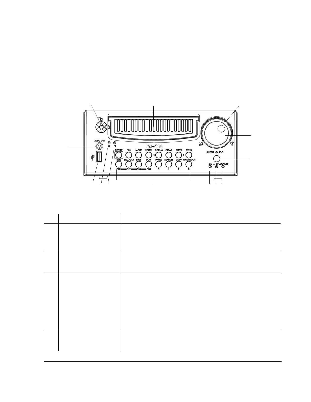
1.3.1. DVR Front Panel Features
The EX4 Plus 35 DVR front panel has important features such as the hard drive
lock, removable hard drive,
buttons, the
USB port, and the VIDEO OUT jack. See Figure 1-1.
Introduction
SHUTTLE/JOG wheel, indicator lights, the DVR
1
13
11
10
Requires the proper key to unlock the hard drive prior to removing
and locking the hard drive during operation. When the DVR is recording,
12
Figure 1-1
Table 1-1
Item Feature Description
EX4 Plus 35 DVR front panel
Front panel features
1 Hard Drive lock (Unlocked
and locked positions)
press the
more information, see “4.3. Replacing the Hard Drive” on page 4–6.)
2
3
4
5
6
8
9
STOP button before unlocking and removing the hard drive. (For
7
2 Removable Hard Drive Remove the hard drive for playback at a remote location using the HD
Reader (see “4.4. Downloading Video to a PC” on page 4–6), swap to
another DVR, or upgrade to a larger hard drive.
3
SHUTTLE wheel
(outer wheel)
• During playback, turnin g the SHUTTLE wheel clockwise speeds the play
forward from 1× to 2×, 4×, 6×, 8×, 16× and 32× the normal speed.
• During reverse playback, turning the
SHUTTLE wheel counter clockwise
speeds the play backward from 1×, 2×, 4×, 6×, 8×, 16× and 32× the
normal speed.
• When the
PAUSE button is pressed, turning the SHUTTLE wheel clockwise
reduces the play to a very slow forward rate.
• When the
PAUSE button is pressed, turning the SHUTTLE wheel counter
clockwise reduces the play to a very slow backward rate.
JOG wheel (inner wheel) • Used to change the values of menu items.
4
• When
PAUSE button is pressed, turning the JOG wheel clockwise or
counter clockwise moves the image one at a time.
700-0058 R001 1–3

Introduction
Table 1-1
Item Feature Description
5 Infrared (IR) Remote
Front panel features
Used with the optional IR remote control pointed at the receiver.
Control receiver
POWER—DVR Power
6
Illuminates when the DVR is powered up.
indicator (green)
7
ALARM—Alarm Event
indicator (red)
8
LAN—Network indicator
Illuminates when an external alarm input has been initiated and remains
illuminated for the duration of the alarm.
Illuminates when connected to an active network.
(red)
9 DVR Buttons See Table 1-2.
10 Hard Drive Access
Illuminates when the DVR is accessing the hard drive.
indicator (yellow)
11 Hard Drive Power indicator
(green)
Illuminates when the hard drive has been properly inserted in the hard drive
tray, and the hard drive lock is in the locked position.
12 USB Port Supports USB devices for:
• Copying video and audio information.
• Exporting video clips (See “4.5.2. Using the ONE-TOUCH Download
option” on page 4–7.)
• Updating the D VR software.
• Importing/exp ort ing operating settings and profiles.
13
VIDEO OUT—Video Output
jack (yellow)
1.3.2. DVR Buttons
The DVR buttons on the front panel illuminate when the buttons are activated.
The DVR buttons perform more than one function and are described briefly in
Table 1-2.
Chapter 4, “Operating the DVR” provides detailed information on using the DVR
buttons. See “4.1.1 Using the DVR buttons” on page 4–2.
VIDEO OUT jack has the same function as the VIDEO OUT jack on the back of
the DVR. Only one device at a time can be connected to either jack.
VIDEO OUT jack is used for:
• Live viewing
• Playback
• System configuration
1–4 700-0058 R001

Introduction
Table 1-2
Description of DVR buttons
Button Description
POWER W ith the vehicle ignition turned OFF and the DVR powered off, pressing the POWER button
for 3 seconds powers up the DVR, but does not initiate recording.
With the vehicle ignition turned
OFF interval, pressing the POWER button for 5 seconds powers down the DVR immediately.
With the vehicle ignition turned
RECORD DELAY-ON interval powers up the DVR and starts recording.
FULL Use the FULL button in combination with one of the four camera buttons (CH1, CH2, CH3, or
CH4), and the DVR displays the selected camera in full screen display mode.
MODE Pressing the MODE button changes the display.
ZOOM In full screen display mode, pressing the ZOOM button zooms into the screen 2×.
DISPLAY <
While the DVR is recording in live mode, different information can be displayed on the
OFF and the DVR still powered up in the RECORD DELAY-
ON, pressing the POWER button for 5 seconds during the
screen.
<
CLEAR When configuring the DVR, pressing the CLEAR button loads the factory default value into
The < button is used to navigate the menus while configuring the DVR.
the field being edited.
LOCK >
>
MENU Pressing the MENU button enters and exits the main menu of the DVR.
REC (CH1) Pressing the REC button starts the DVR recording if the DVR is not playing video or in the
REV.PLAY (CH2) During playback or when the video is stopped, pressing the REV.PLAY button starts playing
Pressing the LOCK button enables a One-Time password option.
The > button is used to navigate the menus while configuring.
menus. When the DVR is recording, the
REC button is illuminated.
the video in reverse.
STOP (CH3) Pressing the STOP button stops the DVR from recording or playing.
PLAY (CH4) If the DVR is not recording, pressing the PLAY button starts to play the recorded video and
audio.
PAUSE (5) Pressing the PAUSE button pauses the video playback and provides a still frame video
image.
SEARCH (6) Pressing the SEARCH button provides a power search function to quickly find the desired
information. Exit the Search menu by pressing the
COPY (7) Pressing the COPY button take you to the Copy menu. Exit the Copy menu by pressing the
MENU button.
ENTER/ONE-TOUCH (8) While configuring in the menus, pressing the ENTER button lets you navigate to the
MENU button.
selected sub-menu.
Pressing the
ONE-TOUCH button starts One-touch download. For more information, see
“4.5.2. Using the ONE-TOUCH Download option” on page 4–7.
700-0058 R001 1–5
Introduction
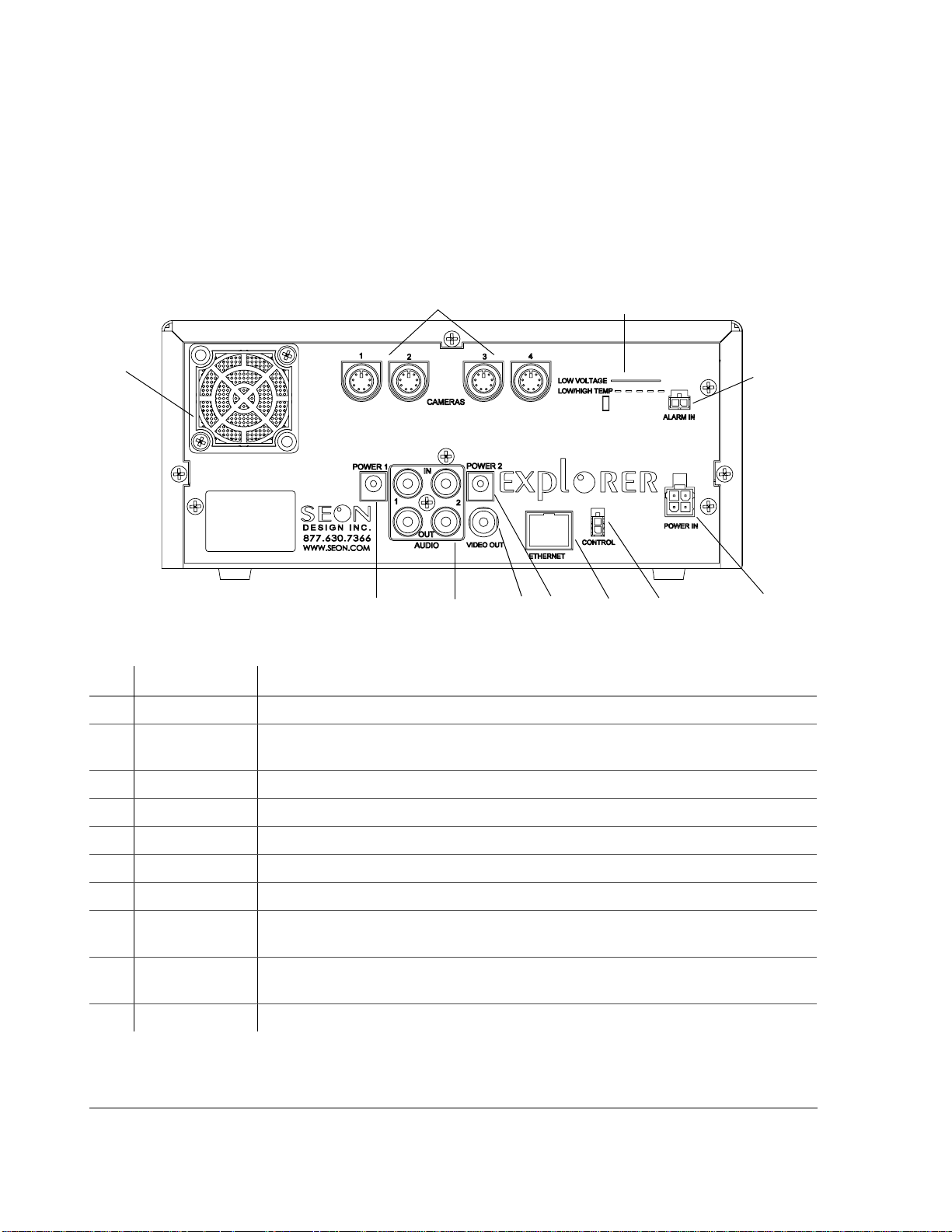
1.3.3. DVR Back Panel Features
The back panel of the EX4 Plus 35 DVR features the inputs where the DVR
connects to the other components of the EX4 Plus 35 System. See Figure 1-2.
Chapter 2, “Installation” provides detailed information on connecting to the back
panel. See “2.5.1. Connecting to the DVR Back Panel” on page 2–8.
1
0
Figure 1-2
Item Feature Description
Back panel
9
8
1 CAMERAS Camera input connectors: 6-pin mini-DIN
2 LOW VOLTAGE
LOW/HIGH TEMP
Low voltage and Low/High temperature indicator (red)
2
3
9
67
5
4
3
ALARM IN Alarm input connector: 2-pin
4
POWER IN Power input connector: 4-pin
5
CONTROL Control connector: 2-pin
6
ETHERNET Network connector: RJ-45
7
VIDEO OUT Video output jack: Yellow RCA style
8
AUDIO IN 1, 2
AUDIO OUT 1, 2
9
POWER 1
POWER 2
10
FAN Fan with filter and removable cover
1–6 700-0058 R001
Audio input jacks: White RCA style for Audio In
Audio output jacks: Red RCA style for Audio Out
Auxiliary Power jacks: 2.1 mm barrels

1.4. Lock Box
Introduction
The lock box secures the DVR into a location on the bus and provides the
following features:
• A locking door which prevents unauthorized access to the DVR controls.
Authorized personnel can use the lock box key to remove the hinged locking
door when access to the DVR is necessary.
• A sliding rail system which allows for easy DVR installation and exchange.
• A slotted cable entry allows connectors to be inserted into the lock box after
installation.
• A removable, hinged locking door, rounded to prevent injury from sharp
edges.
• Mounting patterns that can accommodate installation flat on the floor,
vertically on the floor, or under a seat. (For installing the DVR under a seat,
use of the Underseat Mounting Bracket Kit is recommended. For installing
the DVR in a vertical mount, the Vertical Mounting Bracket Kit is
recommended. Contact your sales representative at Seon Design for more
information.)
1.5. Cables and Harnesses
The wiring connections to the EX4 Plus 35 System includes:
• A camera cable comes with the camera, using a single connector for ease of
installation.
• An ignition input harness.
• A high-reliability power harness for providing power to the DVR.
• A driver’s indicator panel to allow easy event searching on the DVR.
• In-line fuses on the power and ignition lines for added protection.
700-0058 R001 1–7

1–8

CHAPTER 2
Installation
This chapter provides information and procedures for installing the EX4
Plus 35 System.

Installation
2.1. Installing the EX4 Plus 35 DVR and Lock Box
The EX4 Plus 35 DVR is designed to be installed in the lock box which is secured
to the mounting surface using the screws provided. The lock box can be installed
flat on the floor or under a seat (horizontal installation) or vertically on the floor
(vertical installation), depending on your requirements. The lock box has a
removable, hinged locking door, and a slide rail system to allow for easy
installation and exchange of the DVR.
The EX4 Plus 35 DVR has connections to the front and back of the unit which are
secured once the DVR is installed and the lock box is locked. Cable grommets on
the lock box allows connectors to be inserted into the lock box after installation.
Planning an
installation
Materials required You will need these materials to complete the installation:
Longer cables To customize your installation, longer cables are available by contacting your
Check that you have all the system components and inspect the units for any
scratches or damage. The lock box key is required to unlock the door of the lock
box, and remove the components that are placed inside the box for shipping such
as cameras and harnesses.
•EX4 Plus 35 DVR
• DVR keys for securing the removable hard drive
• Lock box
• Lock box keys for securing the hinged locking door
• Cameras
• Driver’s indicator panel
• Seon video recording label (if purchased)
• Smart-Link™ module
• Smart-Link-to-DVR connection harness (10 feet)
• Power and ignition harness (3 feet)
• Fuses: 5 A power fuse and 1 A ignition fuse
• Fuse holders
• Alarm input cable (3 feet)
• Signal harness (3 feet)
• Speed cable (20 feet) (if purchased)
• GPS receiver and cable (if purchased)
• CAN interface cable (if purchased)
• Butt splice connectors
• Four #10 × ¾" sheet metal screws
• Four #10 × 1" self-drilling screws
sales representative at Seon Design.
2–2 700-0058 R001

Important note
Installation
Important:
Design sales representative or dealer for information on the Underseat Mounting Bracket
Kit before starting the installation.
Important:
Design sales representative or dealer for information on the V ertical Mounting Bracket Kit
before starting the installation.
If you are mounting the lock box under a seat, please contact your Seon
If you are mounting the lock box vertically, please contact your Seon
2.2. Step 1: Installing the Lock Box
The lock box has a door and lid which need to be removed in order to secure the
base in its location. The lock box can be mounted either on the floor or underneath
a seat.
Important:
sales representative or dealer for information on the Underseat Mounting Bracket Kit.
The lock box can be installed horizontally (see “2.2.1. Horizontal Installation”).
Four mounting points are located on the base of the lock box for securing the unit
and raising the unit off the mounting surface by 3/16".
The lock box can be installed vertically (see “2.2.2. Vertical Installation” on
page 2–4). Three mounting points are located on the back of the unit for securing
the unit and raising the unit off the mounting surface by 3/16".
If you are mounting the lock box under a seat, contact your Seon Design
Important:
where the cables enter the unit.
It is not recommended that the lock box be installed on its left or right side
2.2.1. Horizontal Installation
To install the lock box horizontally:
1. Unlock the door with the lock box key provided and remove it from the base
of the lock box.
2. Slide the DVR out of the lock box by pulling on the two bracket tabs at the
front of the DVR.
3. Detach the lid from the lock box by removing the two retaining screws on
either side of the lid near the front of the lock box.
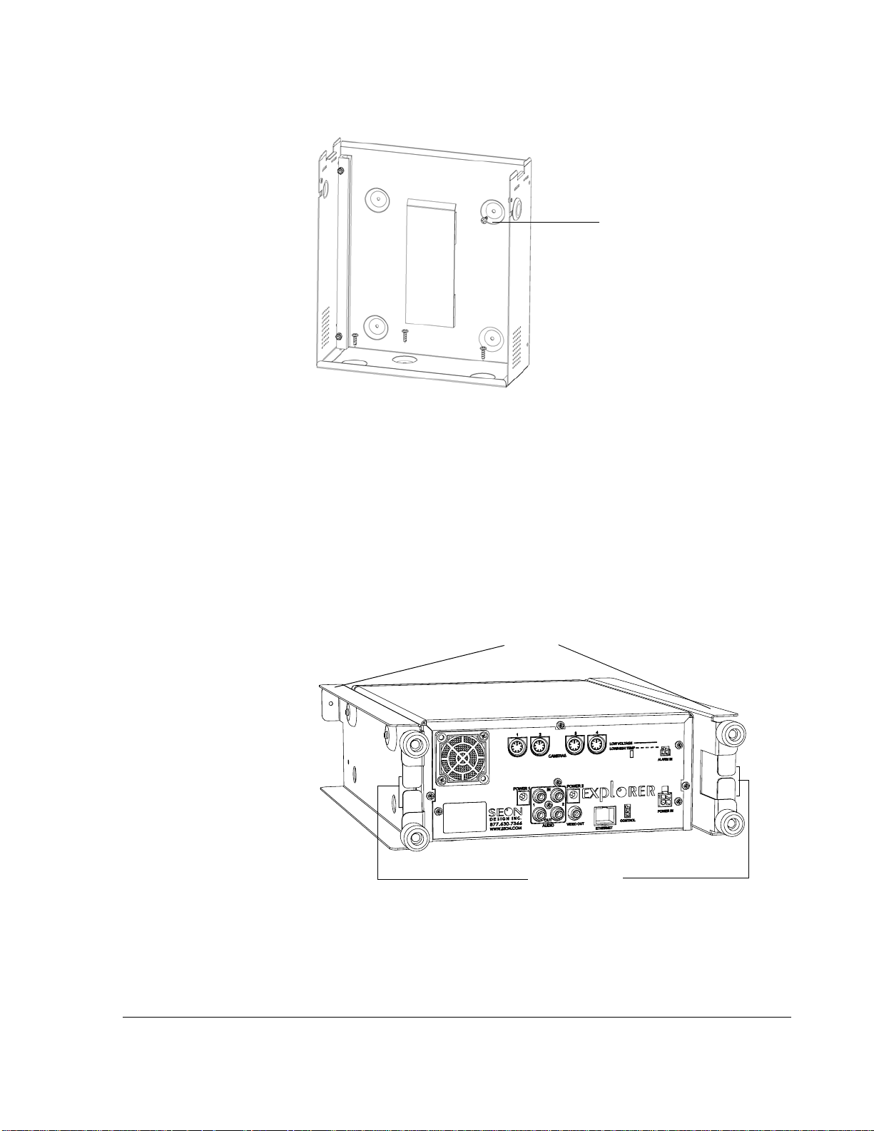
4. Determine whether the power and camera cables will enter the lock box on
the left or the right side. Swap the cable grommet and the hole plug, if
necessary. See Figure 2-1.
5. Use the four #10 × ¾" sheet metal screws or #10 × 1" self-drilling screws to
secure the base of the lock box to the floor.
6. Slide the lid on to the lock box and secure it with the two retaining screws.
700-0058 R001 2–3
Installation
Cable grommet
Figure 2-1
2.2.2. Vertical Installation
For installation in a difficult location, the lock box can be mounted vertically.
Important:
help stabilize the lock box in a vertical installation. If you are mounting the lock box
vertically , please contact your Seon Design sales representative or dealer for information
on the Vertical Mounting Bracket Kit before starting the installation.
To install the lock box vertically:
1. Unlock the door with the key provided and remove it from the lock box base.
2. Slide the DVR out of the lock box by pulling on the two bracket tabs at the
front of the DVR.
3. Detach the lid from the lock box by removing the two retaining screws on
either side of the lid near the front of the lock box.
4. Determine if the power and camera cables will enter the lock box on the left
or the right side. Swap the cable grommet and the hole plug, if necessary.
5. Use 3 of the enclosed #10 × ¾ sheet metal screws or #10 × 1 self-drilling
screws to attach the lock box to the floor. See Figure 2-2.
6. To prevent excess vibration, use the remaining #10 × ¾ sheet metal screw or
#10 × 1 self-drilling screw to secure the lock box to a vertical surface.
7. Reattach the lock box lid using the two screws removed earlier.
Hole plug
Lock box horizontal installation
It is highly recommended that the V ertical Mounting Bracket Kit is used to
2–4 700-0058 R001
Vertical mounting
screw
Installation
Figure 2-2
Lock box vertical installation
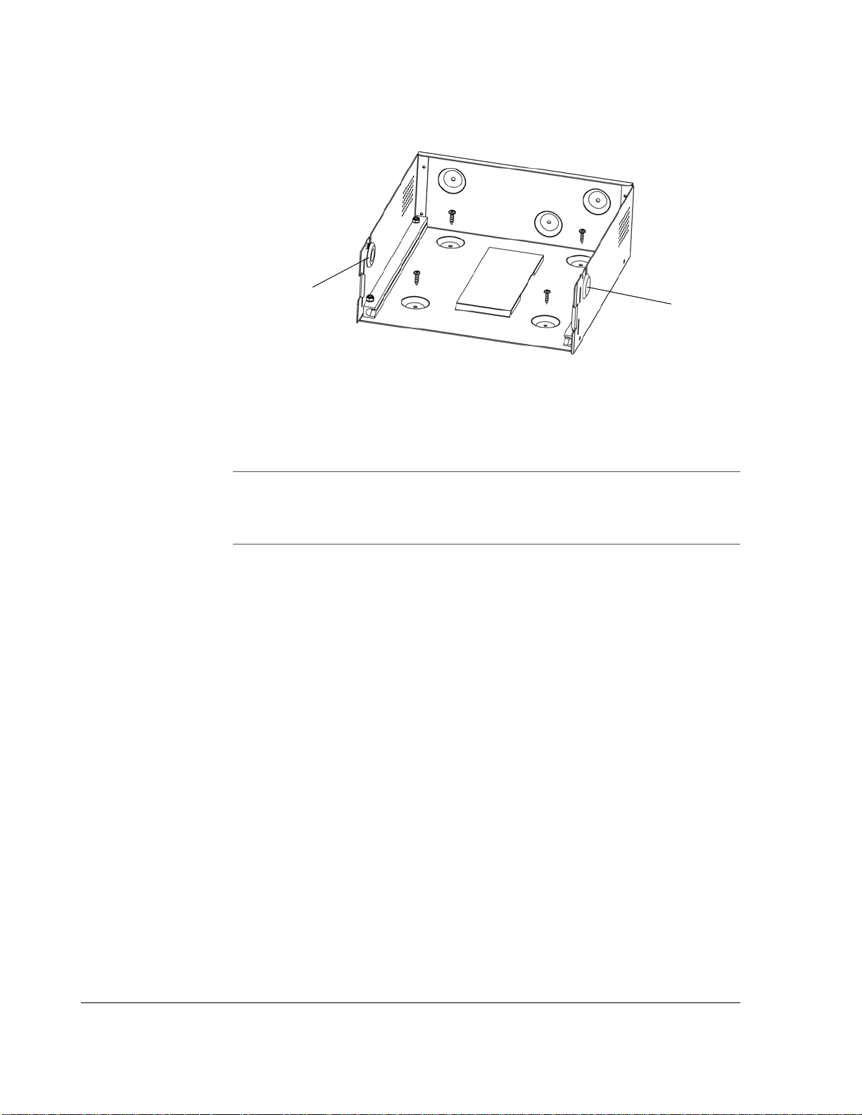
2.3. Step 2: Installing the DVR in the Lock Box
The DVR has two brackets attached to the sides that allow it to slide easily in and
out of the lock box. The brackets also enable easy top-up orientation of the DVR
when the unit is installed on the floor or under a seat.
The rear of each bracket has two plastic retainers that allow cables to easily slip in
between to ensure they do not get pinched at the back of the lock box when the
DVR slides in. See Figure 2-3.
Brackets
Cable retainers
Figure 2-3
700-0058 R001 2–5
Brackets and cable retainers
Installation
2.4. Step 3: Installing the Cameras
If you have purchased cameras from Seon Design, install the cameras according
to the documentation that shipped with the product.
If you have cameras already installed, see “2.4.1. Checking the Camera Cable
Connections”.
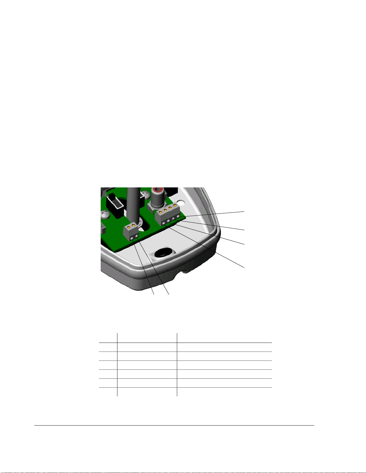
2.4.1. Checking the Camera Cable Connections
The EX4 Plus 35 System uses an integrated mini-DIN connector for all of the
camera signals. The cable comes prewired into the camera, but if the cable
becomes disconnected, reattach into the terminal blocks inside the camera. See
Figure 2-4. The cable colors for correct wiring to the terminals are described in
T able 2-1. For comp lete camera information, see the product insert for the camera
(for example, SA Series Wedge Camera Setup Guide document part number 700-
0004).
1
5
6
Figure 2-4
Table 2-1
Item Color Description
1 Red Power positive (+)
2 Black (and silver) Power gro und (–)
3 Green Audio positive (+)
4 White Audio ground (–)
5 Yellow or orange Video positive (+)
6 Blue or brown Video ground (–)
Terminal blocks in the camera
Camera cable wiring
2
3
4
2–6 700-0058 R001

Surface run
Installation
Concealed
Installation
Installation
The camera cable should be long enough to reach from a camera mounted to the
header or ceiling of a bus down to the DVR lock box. Different cable lengths can
be obtained by contacting Seon Design.
The camera cable can be surface run or concealed.
If the installation is surface run, ensure that the camera cable is secured at multiple
points and is protected from sharp corners.
If the cable is concealed, it can be pulled from either end. Pulling from the
connector end requires larger holes in panels. Pulling from the wire end requires
the cable to be disconnected from the camera.
Feed the cable through the large cable grommet on the DVR lock box. The
connectors can be fed through the grommet one at a time, or the grommet can be
cut at the top and the cables can be simply slid into the grommet. Leave enough
cable in the DVR lock box to allow the DVR to slide all the way back.
700-0058 R001 2–7
Installation
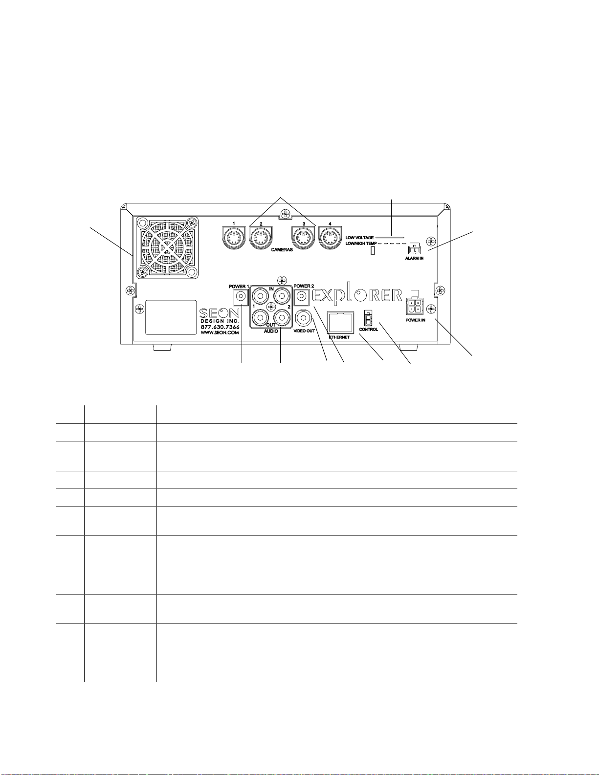
2.5. Step 4: Connecting the DVR
2.5.1. Connecting to the DVR Back Panel
Figure 2-5 shows the back panel of the EX4 Plus 35 DVR which provides the
connectors for the camera inputs, alarm input cable, power input harness, control
cable, Ethernet, video in and out, audio in and out, and power.
1
10
7
Figure 2-5
Item Feature Description
Back panel connections
9
8
1 CAMERAS Four camera input connectors: 6-pin mini-DIN
2 LOW VOLTAGE
LOW/HIGH TEMP
Low voltage and Low/High temperature indicator (red) illuminates if the voltage is low.
(See “4.6. Voltage Display” on page 4–13.)
2
3
4
9
6
5
3
ALARM IN Alarm input connector (2-pin) for connecting the alarm input cable.
4
POWER IN Power input connector (4-pin) for connecting the Smart-Link-to-DVR harness.
5
CONTROL Cont rol connector (2-pin) for connecting external devices and controlling the wireless
bridge equipment.
6
ETHERNET Network connector: RJ-45 for connecting to LAN. Ethernet is used to connect either to a
PC or directly to the wireless bridge equipment.
7
VIDEO OUT Vi d e o output jack (yellow RCA style) for playback. (A video output jack is also provided
on the front panel of the DVR. Only one device at a time can be connected to either jack.)
8
AUDIO IN 1, 2
AUDIO OUT 1, 2
9
POWER 1
POWER 2
10
FAN Fan with filter and removable cover keeps the unit cool. (For maintaining the filter, see
Audio input jacks (white RCA style) used with the two power output jacks for optional
remote microphones or IR modules. Audio output jacks (red RCA style) for playback.
Auxiliary Power jacks (2.1 mm barrels)
“5.1.3. Replacing the Fan Filter” on page 5–2.)
2–8 700-0058 R001
 Loading...