

Page 1
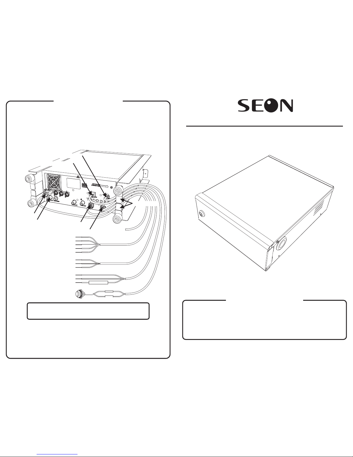
Camera 1
harness
Alarm switch
Fuse holder
Connectors
DVR
(rear view)
Speed harness
Signal harness
Optional external
audio input for camera 1
Power and ignition harness
Alarm harness
Cable retainers
To camera 1
Battery + (red)
Battery (black)–
Ignition switch (yellow)
Left turn signal, indicator 1 (black)
Stop arm, indicator 2 (green)
Brakes, indicator 3 (red)
Warning lights, indicator 4 (brown)
Right turn signal, indicator 5 (white)
Speed sensor ground (black)
Speed pulse signal (green)
Speed sensor power 7.5 (red)
VDC
Wiring and Testing
1
Feed all of the through the cable grommet and connect them to
the DVR as shown below.
harnesses
2
Make sure all cables are held inside the cable retainers at the back of the
DVR, as shownbelow. Carefully slide the DVRinto the enclosure, takingcare
not to pinch or bind any cables. Slide the lid onto the enclosure and secure it
with two #8×¼" retaining screws.
3
Connect all of the harnesses as shown above. Turn on the ignition switch. If
the light onthe front oftheDVR does not turn greenwithin
POWER 30 seconds,
read the troubleshooting instructions in the .Installation and User's Guide
4
Follow the DVR setup instructions in the or
the
Quick Reference Guide
Installation and User's Guide.
IMPORTANT: The DVR must be connected as close to the battery
(or master battery switch) as possible to avoid a low-voltage DVR
shutdown when the battery is heavily loaded.
Information in this guide is subject to change without prior notice.
© 2004 Seon Design Inc. www.seon.com
All rights reserved. Document Part Number: 700-0031-01
TR4-20 Full-Featured Mobile DVR System
Quick Installation Guide
If your TR4-20 Full-Featured Mobile DVR System is to be returned to Seon Design for service, please
call toll free 877-630-7366, or 604-524-6437 and ask for a Return Authorization (RA) number. An RA
number allowsthe Service Technicians to better track your product when it comes in for service. Please
show the RA number on the outside of the package. ANY PRODUCT SENT TO SEON DESIGN
WITHOUT AN RA NUMBERMAY BEREFUSED.
Please refer to the Warranty form provided with your product to review the terms of warranty service,
contact and shipping information, as well asother important issues regarding the service and operation
of your product.
Service and Warranty
Page 2
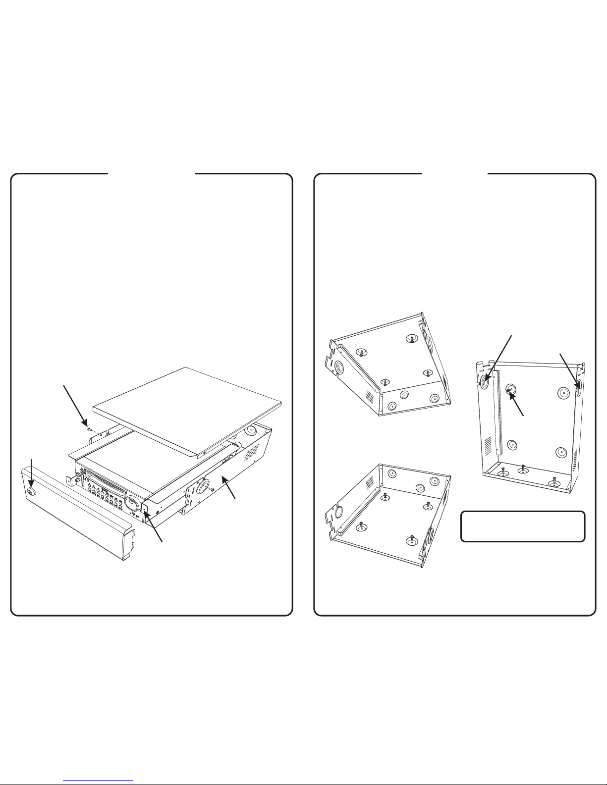
Door
Lid
Ta b
Lock
DVR
Enclosure
#8×¼" screws (2)
1
Use the flat key to unlock the door and remove it
from the enclosure. (The cylindrical key fits the
DVR disk drive lock.)
2
Use a Phillips screwdriver to remove the two
screws that secure the lid to the enclosure.
Remove the lid from the enclosure.
#8×¼"
Disassembly
3
Pull on the tabs on each side of the DVR
to slide it out of the enclosure.
Cable grommet
Hole plug
Floor mount
Underseat mount
Vertical mount
#10×¾" screws (4)
#10×¾" screws (4)
(see note below)
#10×¾" screws (4)
Mounting
1
If necessary, swap the cable grommet
and the hole plug to accommodate the
power and camera cables.
2
Use the four screws supplied
with the TR4-20 to mount the enclosure
horizontally or vertically as shown below.
#10×¾"
NOTE: When mounted vertically,
the enclosure must be attached toa
wall to prevent excessvibration.
 Loading...