

Senztek SolaStat-Plus Installation Manual

™
SolaStat
An Intelligent Technology Solution for Water Heating
-1-3
INSTALLATION GUIDE
FOR QUALIFIED PERSONNEL ONLY


SolaStat™-1-3 Installation Guide
Version 1.1– April 2013 Table of Contents
Table of Contents
Before You Begin Installation .................................................................................... 1
Installing the SolaStat™ Controller ............................................................................ 5
Mounting the Sensors and Connecting Wiring ........................................................... 7
Powering Up............................................................................................................ 10
Plumbing Tips ......................................................................................................... 13
About the Pump Settings ......................................................................................... 16
Programming the SolaStat™ ................................................................................... 18
Sensor Maintenance ............................................................................................... 26
Trouble Shooting Guide .......................................................................................... 28
Programming Table ................................................................................................. 30
Specifications .......................................................................................................... 31
www.senztek.com
Senztek Holdings Ltd. 2009
SolaStat™-1-3 Installation Guide
Version 1.1 – April 2013 Page 1
BEFORE YOU BEGIN INSTALLATION
Assemble the
components
you will need
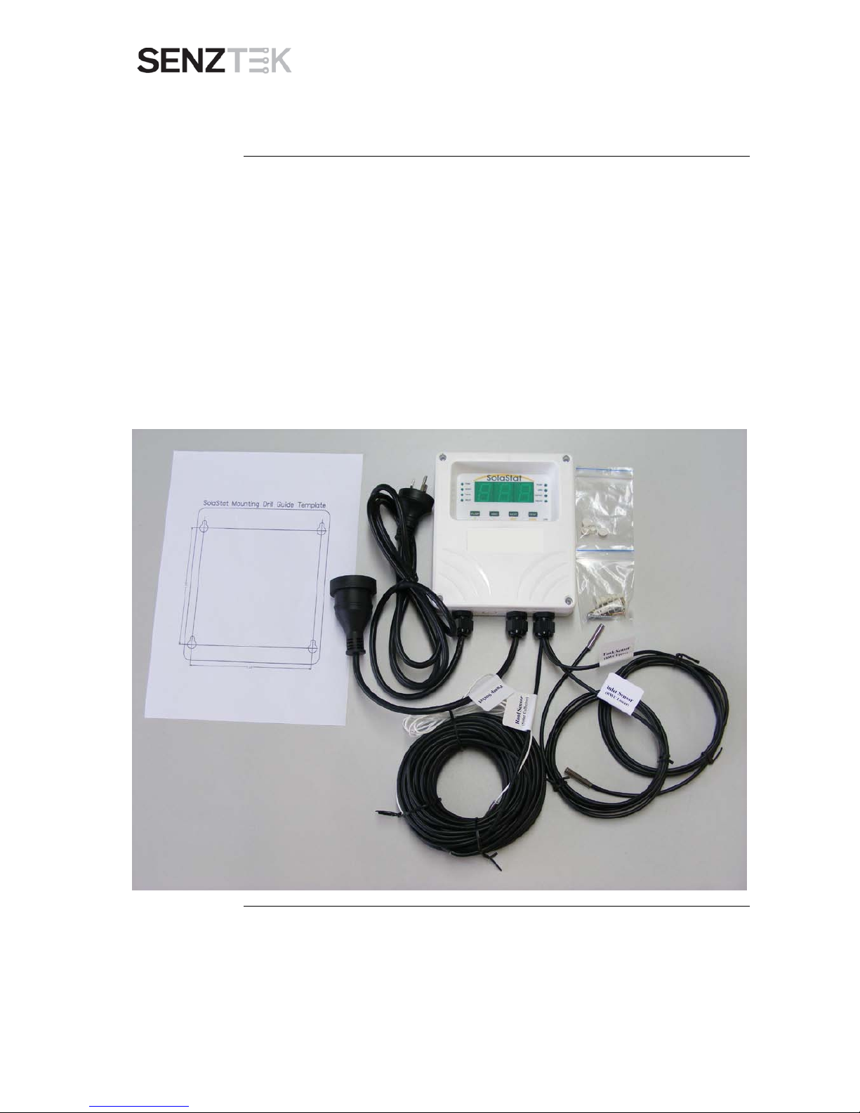
The SolaStat™ Controller is supplied with the following components:
Roof sensor
Tank sensor
Inlet sensor
Mains cable
Pump cable
Associated screws
Mounting guide
Screw covers
Continued on next page
SolaStat™-1-3 Installation Guide
Version 1.1 – April 2013 Page 2
BEFORE YOU BEGIN INSTALLATION, CONTINUED
Assemble the
tools you will
need
You will need the following tools to install the SolaStat™:
Philips1 screwdriver for lid screws
Pozi 2 screwdriver for mounting screws
Note: These tools are needed to mount the SolaStat™ only, and other tools
may be needed for the remainder of the installation including the sensors.
READ THESE SAFETY PRECAUTIONS and LIMIT OF LIABILITY BEFORE YOU BEGIN
The following pages contain instructions for qualified personnel only. They involve potentially
hazardous adjustments and high voltage mains wiring information.
General
Safety
Precautions:
The following general safety precautions should be noted:
This installation guide is for the installation of SolaStat
TM
The complete installation should be checked at least annually for damage
or malfunction.
Controllers only and
is not an installation guide for any other part.
All servicing must be carried out by an authorised service agent only.
All aspects of the installation must comply with local electrical and
plumbing regulations (and any special solar hot water regulations).
Continued on next page
SolaStat™-1-3 Installation Guide
Version 1.1 – April 2013 Page 3
BEFORE YOU BEGIN INSTALLATION, CONTINUED
Installation
Precautions
Installers need to ensure the following:
The controller must be installed away from water sources such as rain,
leaking pipes, or wet floors; and must not be installed in damp areas like
bathrooms. The controller must have a waterproof enclosure if it is
installed outside.
Make sure the controller is installed away from direct sunlight,
flammable liquids or radiant heat sources.
Power leads must face directly down, not sideways or upwards.
Ensure the controller is in a safe environment for users to inspect
display panel.
Follow instructions carefully when mounting sensors. Incorrect sensor
mounting can lead to a poorly controlled solar hot water system with
safety issues (e.g. overheating; over pressure damage to the plumbing;
freezing damage to the solar collector).
The unit settings are factory programmed to optimise efficiency and
safety. Alteration of the programmed values can lead to dangerous
conditions and/or damage to parts of the solar hot water system.
Note that the Sola-2-3at
TM
- ST is factory set to display temperature in
degrees Centigrade/ Celsius. The Sola-2-3at
TM
- 2F is factory set t o
display temperature in degrees Fahrenheit. These settings cannot be
changed. Refer to the label on the side of the enclosure and the box.
CAUTION:
Dangerous Voltages may be present. The SolaStat
TM
Protective enclosure must only be opened by qualified personnel.
has no user
serviceable parts.
Remove ALL power sources before removing protective cover.
Continued on next page

SolaStat™-1-3 Installation Guide
Version 1.1 – April 2013 Page 4
BEFORE YOU BEGIN INSTALLATION, CONTINUED
Electrical
Precautions:
When undertaking electrical installations, please note the following
All mains voltage electrical work must be carried out by a qualified
electrician, especially external power outlet socket installation.
A readily accessible disconnect device, overcurrent device and RCD
Protection rated to suit the size of the pump plus 5VA must be
incorporated in the power supply wiring. The overcurrent device for a
1500W, 240Vac pump must not exceed 10Amps.
Sensor leads should be kept 300mm away from mains and comms
cables.
Do not use mains power extension cords unless approved by the
manufacturer. Water resistant plugs and sockets should be used.
The SolaStat™ controlled output (PUMP) will be connected to the input
power supply wiring and are not isolated from it. Supply voltages will be
output through that outlet during activation.
Always use the unit within specified voltage and load ranges. Never use
with damaged leads, plugs or sockets.
Do not allow the sensor cable to come within 10mm of the high voltage
connectors or components inside the enclosure.
Comply with all local and relevant electrical regulations.
Warning
These products are not designed for use in, and should not be used for,
applications which are in conjunction with items that are critical to any
person’s health (e.g. life support systems).
In any critical installation, an independent fail-safe back-up system must
always be implemented.
SolaStat™-1-3 Installation Guide
Version 1.1 – April 2013 Page 5
INSTALLING THE SOLASTAT™ CONTROLLER
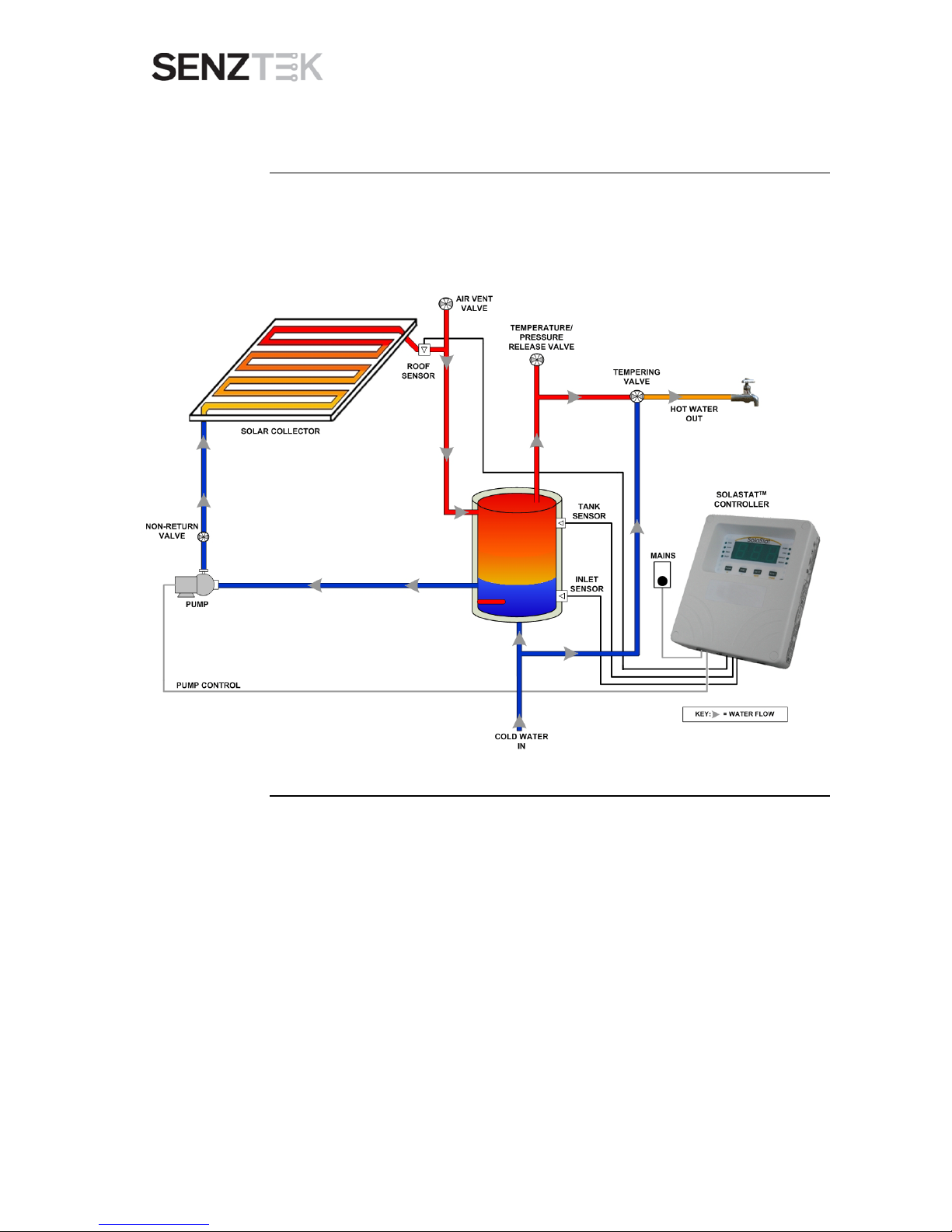
Overview
The diagram below shows how the SolaStat™ is connected to the Hot Water
Cylinder (HWC), the collector, and the three sensors (ROOF, TANK and
INLET).
Continued on next page

SolaStat™-1-3 Installation Guide
Version 1.1 – April 2013 Page 6
INST ALLING THE SOLASTAT™ CONTROLLER, CONTINUED
Where to
mount the
SolaStat
TM
The SolaStat
TM
Controller should be mounted so that:
1. It is against a flat surface with sufficient strength to hold the enclosure
and any additional weight from the plugs, sockets and cables,
2. Power leads face down not sideways or up.
3. It is safe for users to inspect,
4. The display can be easily read and buttons accessed, and
5. Allowance is made for cable runs, location of power outlets and lengths
of wir es.
Mounting the
SolaStat
TM
Note: In general, you should not need to open the Controller unit during
installation unless the installation is for a Hot Water Cylinder with two
elements.
Follow these steps:
1. Allow for the enclosure dropping 5 mm (1/5 inch) from screw centres
once mounted (keyhole mounting).
2. Place the drill guide template against wall, checking for level alignment.
Four screws are supplied: two chipboard screws and two combination
plasterboard/ wood screws.
All four mount ing holes should be used with at least two firmly secured
into wood.
The outer plastic plasterboard anchors will self tap into plasterboard and
their inner metal screws fix into the centre of the plastic anchors.
3. Mark and drill/ screw as appropriate leaving the heads of the screws
above the surface by approximately 3 mm (1/8 inch).
4. Place the unit over the four screw heads. The unit should slide down
5mm into the ‘key’ slots and become secured to the wall. You will need to
adjust the screw height to obtain a secure fit.
SolaStat™-1-3 Installation Guide
Version 1.1 – April 2013 Page 7
MO UNTING THE SE NSOR S AND CONNECTING WIRING
Introduction
The locations and way that the sensors are mounted is critical to ensure the
SolaStat™ -
operates correctly and at greatest efficiency;
protects the system against damage from extreme temperatures, and
displays hot water readings are accurately.
If the TANK and/ or INLET sensor is not mounted correctly –
There may be inaccurate Topout sensing, which could lead to damage to
the Hot water cylinder or other components
Hot water readings on the display may be inaccurate
If the ROOF sensor is not correctly mounted –
The unit may not be able to detect FROST settings (this can lead to the
collector panel bursting)
Please follow the instructions below carefully.
Positioning
the ROOF
Sensor
The ROOF Sensor should be fitted into a metal immersion ‘pocket’ in the hot
water outlet pipe.
Apply plenty of heat transfer compound (available from your distributor)
between the sensor and the lining of the hot water outlet pipe.
Seal the sensor with neutral cure sealant and install external lagging. The
cable should also be insulated from the bare pipe.
Positioning
the TANK
Sensor
The TANK Sensor should be fitted into a metal immersion ‘pocket’ in the
upper region of the Hot Water Cylinder (HWC) (typically 1/3 of the way down
from the top of the HWC, or the first possible place below 1/3 of the way
down.
If a ‘pocket’ is not available, use S3 mount (available from your distributor).
Apply plenty of heat transfer compound (available from your distributor)
between the sensor and the lining of the ‘pocket’ (or between the tank and
the sensor).
Continued on next page
SolaStat™-1-3 Installation Guide
Version 1.1 – April 2013 Page 8
MOUNTING THE SE NSO R S AND CONNECTING WIRING, CONTINUED
Positioning
the INLET
Sensor
The INLET Sensor should be fitted into a metal immersion ‘pocket’ above the
HWC electric element near the bottom of the tank (usually just above the
element).
If a ‘pocket’ is not available, then bond the sensor against the metal wall of
the tank (not the outside cladding or insulation).
Apply plenty of heat transfer compound (available from your distributor)
between the sensor and the lining of the ‘pocket’. (or between the tank and
the sensor).
Precautions
Please note:
Removing or cutting the cladding may void the hot water tank warranty.
The sensor must not be immersed in water.
Unless the temperature probe is designed for immersion in water,
temperature probe pockets need to be completely dry before you insert
the probe; and the pocket must be protected against moisture entry after
the probe is fitted.
Sensor leads should be kept 300mm (12 inches) away from mains and
communications cables.
Make sure the right sensors are mounted in the right places!
Continued on next page
 Loading...