

USER GUIDE
SolaStat
™
-2-3
An Intelligent Technology Solution for Water Heating


SolaStat™-2-3 User Guide
Version 1.11 – November 2011 Table of Contents
Table of Contents
Introducing your SolaStat™ Controller ....................................................................... 1
The Display Panel ...................................................................................................... 2
Saving Power with SolaStat™ .................................................................................... 3
Using your SolaStat™ ................................................................................................ 4
Trouble Shooting Guide ........................................................................................... 10
Programming Table .................................................................................................. 11
For technical help contact your installer or maintenance technician.
Installer Details:
www.senztek.com
Senztek Holdings Ltd. 2009

SolaStat™-2-3 User Guide
Version 1.11 – November 2011 Page 1
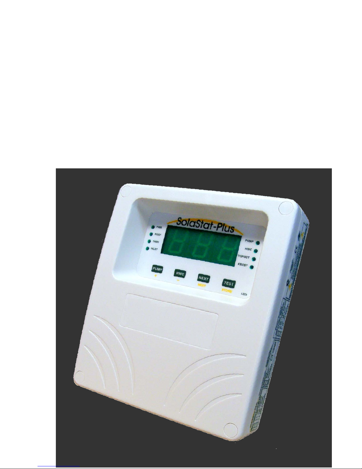
INTRODUCING YOUR SOLASTAT™ CONTROLLER
About Your
SolaStat™
Controller
Your SolaStat™ Controller has a microcomputer, which intelligently and
automatically controls water flow and energy inputs into your hot water
system.
Your SolaStat™ will balance water flow and energy inputs from solar, and
electrical sources so you can minimise your energy costs.
It has two main aims:
To make sure your hot water is being heated cost-efficiently.
To make sure you don’t run out of hot water when you need it.
How Does It
Work?
Your SolaStat™ Controller works by measuring and comparing the
temperature at three different places in the system: the collector (ROOF), the
top of your hot water cylinder (TANK) and the bottom of your hot water
cylinder (INLET).
If the temperature at the ROOF is higher than the INLET temperature by a
pre-set amount, then the pump turns on automatically to transfer heated
water from your solar collector to your hot water cylinder, and replace it with
cooler water from the bottom of the cylinder.
This makes the hot water cylinder heat up and the collector on your roof cool
down. When the temperature difference reduces to the pre-set level again,
the pump automatically stops.
It can also optimise the timing of heating your water, so heat is only applied
to the water in your cylinder when necessary, not all the time.
The SolaStat™ is also designed to protect your hot water system from very
high or freezing temperatures, as well as make sure that safe water
conditions are maintained (BioSafe).
SolaStat™-2-3 User Guide
Version 1.11 – November 2011 Page 2
THE DISPLAY PANEL
The
ROOF,
TANK
and
INLET lights indicate
which temperature is
being displayed.
If any of these lights
flashes, the unit is in
Smart Shutdown Mode
and ‘SSd’ will be
displayed.
NEXT Button
Press to obtain the next
displayed temperature.
The DISPLAY PANEL
shows
the temperatures of the
relevant sensors in 0C or 0F.
This is factory pre-set and
cannot be changed.
HWC Button
Press and let go for a one-off user heat up to
a maximum temperature – it will then switch
off and revert to automatic. Press again to
cancel.
When in Programming Mode, use this to
decrease the display value on the screen.
TEST Button
Press to test the display of the screen. ‘888’ will be
displayed and all the lights will be on at the same
time for about two seconds.
All the lights (except the PWR light) will then flash
and the display will show the number of times the
pump has been on (up to 999).
The
PUMP
light comes on when the
pump is on (in normal or FROST
operation, or when the PUMP button is
pressed).
The PUMP light flashes when the
maximum tank temperature has been
reached.
HWC
The HWC light is
on when the
element is on.
The TOPOUT
light is on when
the hot water tank
has reached its
maximum
temperature.
The
FROST
(and PUMP
)
light is on when the pump is
circulating water to stop the
collector from freezing.
CAUTION: Do not turn the
power off when the FROST
light is on.
PUMP
Button
Press and hold this button
to turn the pump on or off
(after it has run for ten
minutes, it automatically
switches off for one
minute, to let air escape
and prevent overheating)
When in Programming
Mode, use this to
increase the display value
on the screen.

SolaStat™-2-3 User Guide
Version 1.11 – November 2011 Page 3
SAVING POWER WITH SOLASTAT™
TThhrreeee TToooollss
ttoo AAcchhiieevvee
PPoowweerr
SSaavviinnggss
SolaStat™ has three tools to help you save power:
1. Controlling the amount of hot water that enters your tank.
You can alter the amount of water entering your tank using the PUMP
function.
Your SolaStat™ is set to make the pump automatically turn on or turn off,
depending on the temperature in the tank, at the inlet and at the collector.
2. Controlling the activity of the heating element.
To ensure that the water in your tank is not heated by electricity
unnecessarily (for example, when the water from your collector is already hot
enough), the heat applied to the element is computer controlled.
3. Running BioSafe as a background activity.
To protect your hot water from harbouring bacteria, hot water tanks need to
be run at 60°C/140°F for at least one hour every 72 hours.
Rather than the traditional method of running your tank continuously at
60
°C/140°F, and using up valuable energy doing so, your SolaStat™
Controller ‘remembers’ when your tank was last heated to 60°C and makes
sure than it heats up to that temperature once every 72 hours for at least one
hour.

SolaStat™-2-3 User Guide
Version 1.11 – November 2011 Page 4
USING YOUR SOLASTAT™
RReeaaddiinngg tthhee
DDiissppllaayy
The Display Lights show where the current display temperature is being read
from: ROOF, TANK, or INLET.
To find out the temperature on the other sensors, press the NEXT button.
The display light will confirm which sensor is being read.
Note that the Sola-2-3atTM- ST is factory set to display temperature in
degrees Centigrade/ Celsius. The Sola-2-3at
TM
- 2F is factory set to display
temperature in degrees Fahrenheit. These settings cannot be changed.
Refer to the label on the side of the enclosure and the box.
Continued on next page
This indicates that
the ROOF sensor
reading is currently
on display, in this
case 370C.
Press NEXT to
toggle between the
ROOF, TANK and
INLET sensors.
This indicates that
the TANK sensor
reading is currently
on display, in this
case 310C.
Press NEXT to
toggle between the
ROOF, TANK and
INLET sensors.
This indicates that
the INLET sensor
reading is currently
on display, in this
case 400C.
Press NEXT to
toggle between the
ROOF, TANK and
INLET sensors.

SolaStat™-2-3 User Guide
Version 1.11 – November 2011 Page 5
USING YOUR SOLASTAT™, CONTINUED
PPuummpp
AAccttiivvaattiioonn
Press and hold the PUMP button to manually operate the pump. It will
circulate the water between the panel and the hot water tank.
After it has run for ten minutes (on automatic or manual), the pump
automatically switches off for one minute, to let air escape and prevent
overheating.
Continued on next page
Press the PUMP
button to manually
pump water from the
collector into the tank.
While the pump is
operating, this light
will be on.
You will see a number displayed on the screen. In
this case, (as the ROOF light is on), it indicates that
the ROOF sensor is at 800C.

SolaStat™-2-3 User Guide
Version 1.11 – November 2011 Page 6
USING YOUR SOLASTAT™, CONTINUED
Manual/User
Reheat
To manually start a reheat of the water in your tank, press the HWC button.
Press the HWC button again to turn it off.
However, if Reheat is already on, pressing the HWC button will not turn it off.
Continued on next page
Press HWC for one-off heat up mode.
This will heat the water to the Reheat
Upper temperature (pre-set to
55°C/131°F.
HWC will flash when the user presses the
HWC button to manually reheat the tank.

SolaStat™-2-3 User Guide
Version 1.11 – November 2011 Page 7
USING YOUR SOLASTAT™, CONTINUED
Testing Mode Pressing the TEST button will make sure the display panel and all lights in
the system are working.
All the lights will stay on, and ‘888’ will be shown for about two seconds.
Then all lights will flash and the display shows how many times the pump has
been activated (up to 999) for three seconds.
Continued on next page
Then, all the
lights (except
the PWR
light) will
flash, and the
display will
tell you how
many times
the pump has
been
activated (in
this case, 123
times).
Press the TEST button
to check that all lights
in the system are
working.
For the next two seconds, all the lights come on and
‘888’ is shown on the screen.

SolaStat™-2-3 User Guide
Version 1.11 – November 2011 Page 8
USING YOUR SOLASTAT™, CONTINUED
Smart
Shutdown
Mode
‘Smart Shutdown’ is a mode that your controller will enter to minimise
damage. It can be activated when the temperature at the ROOF sensor is
less than -40°C/-40°F or more than 142°C/288°F.
This may occur because:
there is a fault in the sensor wiring, OR
the Solar Collector has reached a very high temperature.
If Smart Shutdown Mode is activated, you will see SSd on the display as
shown on the screen below.
The ROOF sensor temperature may reduce to a safe level by itself and the
uniit will return to normal operation. ‘SSd’ will no longer appear on the
display.
This is a normal condition and it is not necessary to contact your installer or
maintenance technician unless ‘SSd is on the display for more than 12 hours.
Continued on next page
SSd on the display shows the controller is in Smart
Shutdown Mode – i.e. there is a fault condition.
When SSd is displayed, the ROOF, TANK or INLET will be on or flashing to indicate which
sensor is faulty. In this case, a faulty ROOF sensor has been detected.

SolaStat™-2-3 User Guide
Version 1.11 – November 2011 Page 9
USING YOUR SOLASTAT™, CONTINUED
Lockout Mode
The Lockout Mode is activated when the water temperature in the collector is
less than 20°C/68°F. In this case, the collector will not contribute any useful
heat, even to cold water.
In this (Lockout) mode, the controller will not turn on the pump even if the
correct temperature differential is reached.
However, if a frost condition is detected, this Lockout Mode is overridden and
the pump operates to protect the system from freezing.
Frost Mode The FROST value is set by your installer. It is shown in the Programming
Table on Page 11.
This function is designed to protect your collector and hot water system from
freezing and bursting.
When the FROST temperature is reached, the pump will come on just
enough to raise the temperature of water by 2-3°C/4-6ºF.
Only a small amount of warm water is needed to protect the collector and
plumbing.
When the unit is in Frost Mode, the FROST and PUMP lights will come on.
CAUTION: Do not turn the power off when the FROST light is on.
As soon as the collector reaches the FROST
temperature, the FROST and PUMP lights will turn on.

SolaStat™-2-3 User Guide
Version 1.11 – November 2011 Page 10
TROUBLE SHOOTING GUIDE
Symptom Cause Solution
No operation, no
display and no lights.
No power/fault.
Check mains outlet.
Check fuses.
POWER light ON but
no display or
corrupted display.
Power brown out (mains power not
running at full voltage).
Unit faulty.
Switch off power while mains
power is in brown out condition.
Switch off power for 10 minutes,
switch on power and see if unit is
operating. If not, unit needs repair.
Contact installer.
Display on, pump not
running, but sunny
outside. Pump light
ON.
Pump damaged or disconnected.
Pump timer has turned pump off.
See if the pump has become
unplugged.
Wait one minute for the pump to
restart.
Pump is running
continuously.
Pump is cavitating.
Special installation.
Setting is incorrect.
Airlock in pipe.
If pump sounds like stones are
passing through it, the pump may
be cavitating. Contact your
installer or maintenance
technician.
Long pump running times may be
normal for a special installation.
Contact your installer or
maintenance technician.
Hot water drops
significantly at night,
yet little or no draw off
be user.
System is reverse thermo-
siphoning.
System is in a high frost area.
Tank is losing heat.
The non-return valve is not fitted
correctly or is malfunctioning.
Discuss non-frost sensitive options
with your energy provider.
Install better insulation on the hot
water tank.
HWC light never
comes on.
Collectors are heating tank to
greater than adjustable values.
Normal operation.
HWC light flashing.
HWC Reheat Upper adjustable
value has not been reached.
Tank Thermostat incorrectly set
Wait for the tank to heat up to
Reheat Upper temperature.
Contact your installer or
maintenance technician.
‘Lo’ on display.
Sensor below -20°C/-4°F. Check outside temperature.
‘Hi’ on display.
Sensor above 139°C/284°F. Check collector has water in it.
‘SSd’ on display.
System is in ‘Smart Shutdown’
Mode.
Contact your installer or
maintenance technician if the
display shows’ SSd’ for more than
12 hours.
Note: When power is removed, the internal timer will keep running for at least 7 days.

SolaStat™-2-3 User Guide
Version 1.11 – November 2011 Page 11
PROGRAMMING TABLE
Your installer may enter special programming information for your controller in the table below.
Settings can be changed by a qualified installer or maintenance technician.
Programming Table for Adjustable Values
Adjustable
Values
Function Light
indication
Pre-Set
Value
Range Installation
Values
Pump Off
The temperature difference
between the Roof and the Tank
that will turn the pump off.
PUMP Flash 6°C
11°F
1-20°C
2-36°F
____ °C
____ °F
Pump On
The temperature difference
between the Roof and the Tank
that will turn the pump on.
PUMP On 12°C
22°F
2-21°C
4-38°F
____ °C
____ °F
Holdoff
Timer
How long the timer will override
the element coming on (as long
as the tank temperature is
above Reheat Lower).
HWC on 4 hours 1-23 hours
>23 hours = OFF
<1 hour = thr
____ hours
Reheat
Lower
The tank temperature at which
the heating element will
automatically start to reheat the
water in your cylinder.
HWC slow
flash
40°C
104°F
1-70°C
34-158°F
<1ºC = OFF
Set Holdoff Timer to
thr = OFF
____ °C
____ °F
Reheat
Upper
The temperature (in the tank) at
which the heating element will
automatically stop reheating the
water in your cylinder.
HWC fast
flash
55°C
131°F
2-90°C
36-194°F
Set Holdoff Timer to
off = OFF
____ °C
____ °F
BioSafe
BioSafe target temperature.
No lights
(except PWR)
60°C
140°F
50-70°C
122-158°F
<50°C = OFF
____ °C
____ °F
Topout
Maximum allowable tank
temperature before the pump is
de-activated to protect system
from overheating.
TOPOUT on 80°C
176°F
1-120°C
34-248°F
<1°C = OFF
____ °C
____ °F
Frost
Minimum allowable panel
temperature before the pump is
activated to protect system from
freezing damage.
FROST on
4°C
39°F
1-10°C
34-50°F
>10°C = OFF
____ °C
____ °F


Senztek NZ Ltd Senztek Australia Ltd Senztek UK Ltd
 Loading...