

Page 1
INSTALLATION INSTRUCTIONS
senvainc.com 1-866-660-8864 (F)1-503-296-2529 9290 SW Nimbus Ave. Beaverton Oregon 97008
REVISION HISTORY
REV DESCRIPTION DATE APPROVED
REVISION HISTORY
REV DESCRIPTION DATE APPROVED
4.0 101
4.7 119
5.4 137
3.7 94
4.4 113
7.5 190
1.9 48
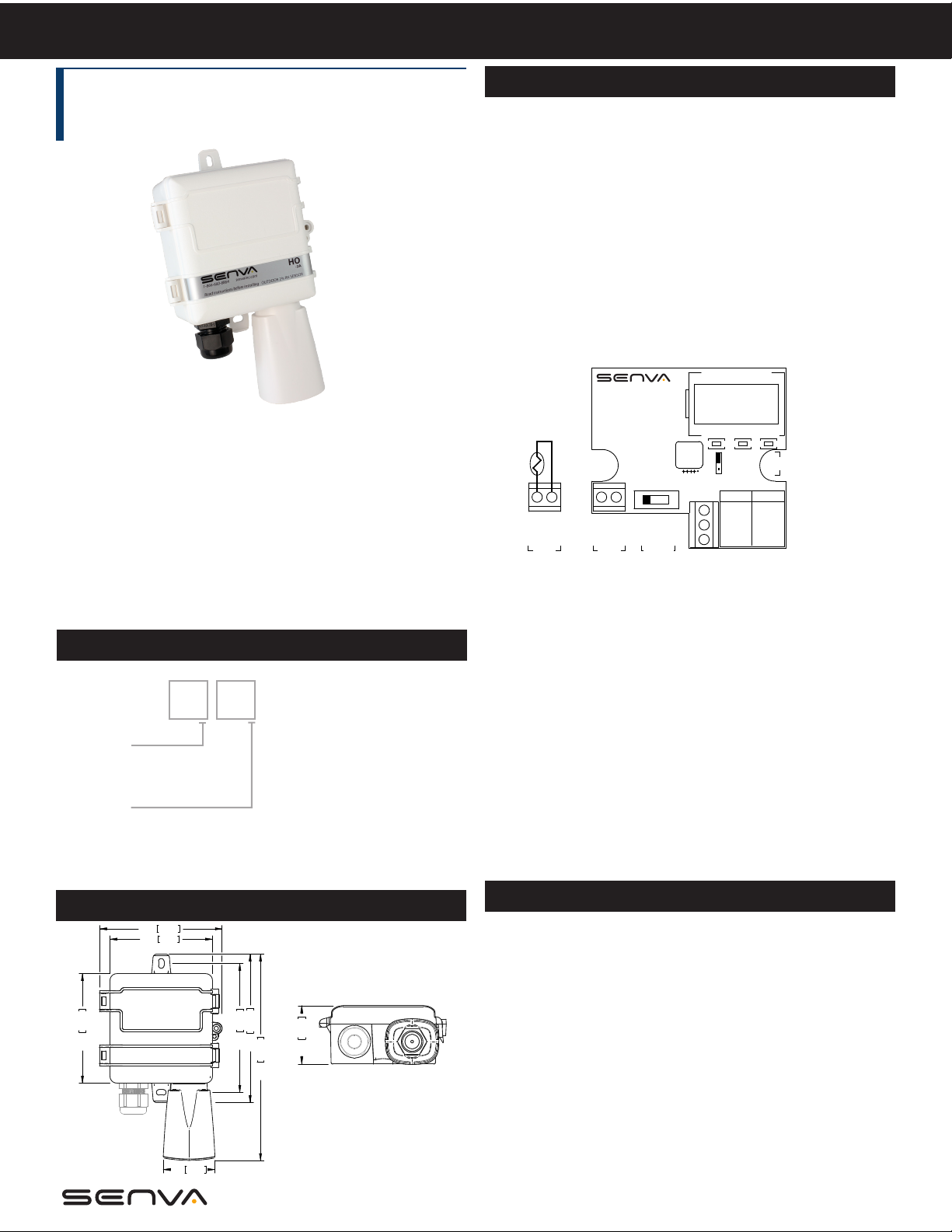
HO, Outside Air
RH and RH/T Transmitters
IMPORTANT WARNINGS
• Only qualied trade installers should install this product
• This product is not intended for life-safety applications
• Do not install in hazardous or classied locations
• The installer is responsible for all applicable codes
• De-energize power supply prior to installation or service
PRODUCT APPLICATION LIMITATION:
Senva products are not designed for life or safety applications. Senva products
are not intended for use in critical applications such as nuclear facilities, human
implantable device or life support. Senva is not liable, in whole or in part, for
any claims or damages arising from such uses.
INSTALLATION
1. Select an outdoor location under an eave on north side of
building away from direct sunlight and rain exposure.
2. Mount product to building with supplied screws.
3. If installing with a conduit adapter, remove and replace the
factory-installed cable gland.
4. Select output type using “OUTPUT SELECT” switch (not
applicable for thermistors).
5. Wire sensor as appropriate for the selected output type.
6. Temperature transmitter models only: Select temperature
output range using “TEMP SELECT” jumper. Not applicable to
thermistors.
RH/T DUAL TRANSMITTER
INC
32-122OF
-40-140
4-20mA
---
mA OUT
V+ PWR
OF O
DEC
O
F
0-5V/10V
V OUT
V- COM
V+ PWR
C
RH
TEMP SELECT
WWW.SENVAINC.COM
< OR >
0-10v
0-5v
4-20mA
V OUT
TH
TH
RTD/
THERMISTOR
(OPTION)
mA OUT
TEMP
TRANSMITTER
(OPTION)
OUTPUT
SELECT
4-20mA wiring:
mA OUT = 4-20mA output return
V+ PWR = Loop supply voltage
SET
MENU
RH%
PRODUCT IDENTIFICATION
RH TEMP
0-5V/0-10V wiring:
V OUT = Voltage output, 0-5 or 10VDC
V- COM = Ground/Common
HO -
V+ PWR = Power supply voltage
Accuracy
2 = 2%
3 = 3%
7. Apply power to sensor.
8. Tighten cable gland rmly around wires. If installing with a
Temperature
A = None
B = Transmitter
C = 100Pt (385)
D = 1000Pt (385)
E = 10k type 2
F= 10k type 3
G = 10k type 3 w/11k
shunt
H = 3k
I = 2k2
J = 1k8
K = 20k
L = 100k
DIMENSIONS
4.4 113
3.7 94
conduit adapter, seal wire entry to prevent conduit air from
aecting sensor readings or operation.
9. Close lid and tighten screw. Cover must be securely installed
to prevent moisture from entering enclosure.
OPERATION
In normal operation, display toggles between %RH and Temp.
For manual oset
set:
Temp units
(1)
, press MENU button to select parameter to
o
F or oC
RH oset -5 to 5% RH in 0.1% RH increments
4.0 101
4.7 119
5.4 137
2.1 53
7.5 190
Temp oset
Press INC or DEC to change value of selected parameter.
Press MENU button to move to next parameter.
(2)
-5 to 5o in 0.1o increments
Settings are saved automatically.
(1) See CALIBRATION section prior to making adjustments.
1.9 48
(2) Temperature oset does not apply to thermistors.
Page 2
SPECIFICATIONS
Power supply 3-wire voltage mode (0-5V/10V)
2-wire current mode (4-20mA)
Outputs RH and Temperature (option) 3-wire 0-5V/10V
Output scaling
Thermistor/RTD options See ordering table
Media lter Sintered stainless steel
Relative Humidity
Temperature (Transmitter)
Enclosure
(1) One side of transformer secondary is connected to signal common. Dedicated transformer is recommended.
(2) Time for reaching 63% of reading at 25oC and 1 m/s airow.
(3) Long term exposures to conditions outside normal range or high humidity may temporarily oset the RH reading (+3%RH after 60 hours).
(4) 15-30VDC/24VAC power supply voltage required for 10 volt output.
RH 0-100%RH
Temp. transmitter (jumper selectable) 32~122oF (0~50oC) or -40~140 oF (-40~60oC)
Accuracy
Resolution 0.05%RH
Hysteresis ±1%RH
Non-linearity Factory linearized <1%RH
Temperature coecient Fully compensated by on-board sensor
Response time
Update rate 2s
Operating range 0 to 100%RH (non-condensing)
Long term drift <0.5%RH per year
Operating conditions
Accuracy (-20 to 70oC range)
Resolution 0.01oC
Repeatability ±0.1oC
Response time
Output update rate 2s
Operating range -40 to 158oF (-40 to 70oC)
Materials ABS/Polycarbonate
Dimensions 4.0”h x 4.4”w x 2.1”d (+2.8” solar shield)
(2)
(3)
(2)
12-30VDC/24VAC
12-30VDC, 30mA max.
2% models: ±2% over 10 to 90% range
3% models: ±3% over 20 to 80% range
30s
-4 to 140oF (-20 to 60oC) @ RH >90%
-4 to 158oF (-20 to 70oC) @ RH = 50%
2% models: < ±1oC; 0.5oC typ@25oC
3% models: < ±2oC; 0.5oC typ@25oC
30s
(1)
, 15mA max.
(4)
or 2-wire 4-20mA
TROUBLESHOOTING
Symptom Solution
No output
Temp or RH reading error
Sensor damage,
contamination, or long-term
drift
Check wiring. Ensure power
supply meets requirements.
Verify unit is located out of
direct sunlight.
Verify control panel software
is congured for correct
output scaling.
Verify accuracy of test instrument. Observe installation
and calibration guidelines.
Oset calibration only if
necessary.
Replace sensor element.
Consult factory for ordering
information.
CALIBRATION
Senva RH sensors are factory calibrated to NIST traceable
standards. No eld calibration is necessary or recommended.
However, to facilitate compliance with commissioning
requirements eld calibration osets are allowed.
1. Locate calibration instrument and sensor in close proximity
to each other in a controlled environment free of drafts, people,
and equipment to reduce inuence on RH and temperature.
2. Allow both readings to stabilize (10-30 minutes). Compare
reading of sensor to calibration instrument, and calculate
dierence.
3. Refer to OPERATION section to change osets as needed.
Setting an oset of zero restores factory calibration.
Revised 3/27/2017 Document #152-0090-0C
 Loading...