

CurveTrack
®
System
Installation Guide
Install Guide P/N : 0309-0218-00
VIDEOSURVEILLANCE SYSTEMS
SENTRY
WAY
®
CT V2 001
SENTRYWAY
Les Carrés du Parc
10 rue des Rosiéristes
69410 Champagne au Mont d’Or


VIDEOSURVEILLANCE SYSTEMS
SENTRY
WAY
®
CT V2 001
Page 3 of 70
System Installation Guide
CurveTrack
®
System
Installation Guide
Installation Guide Revision Status :
Rev. Description of Change Date Approval
Sentryway - Les carrés du Parc - 10 rue des Rosiéristes - 69410 Champagne-au-Mont-d’Or
Phone : 06 64 78 59 57 - Website : www.sentryway.com
e CurveTrack® is a product of Sentryway, and is protected patents.
is document discloses information proprietary to Sentryway, and no intent to abandon such proprietary
information or to grant any rights to the recipient, is to be inferred from any transfer of this document. All
transfers of this document, except where express written consent has been granted, are made subject to the
conditions that the document not be reproduced, copied, or otherwise represented either in whole or in part,
and that no part of its contents or any embodiment thereof will be divulged or used in connection with any
matters other than for Sentryway
STATEMENT OF CONFIDENTIALITY

VIDEOSURVEILLANCE SYSTEMS
SENTRY
WAY
®
CT V2 001
Page 4 of 70
System Installation Guide
CAUTION
It is essential that safety precautions noted throughout this manual be followed
along with OSHA Safety Standards and local electrical codes at the installation
site. To prevent personal injury, use the safety equipment specied in the
Recommended Tool list elsewhere in this manual.
SENTRYWAY reserves the right to modify the contents of this manual at any
time. Sentryway shall not be held liable for errors contained herein or for incidental or consequential damages in connection with furnishing, performance,
or the use of material in this manual.
NOTICE TO USERS

VIDEOSURVEILLANCE SYSTEMS
SENTRY
WAY
®
CT V2 001
Page 5 of 70
System Installation Guide
Table of Contents
1. INTRODUCTION...............................................................................................................7
1.1 Explanation of Symbols.............................................................................................................................8
1.2 Technical Specications............................................................................................................................9
1.2.1 Physical Dimensions of the camera carriage..........................................................................................10
1.3 Units of measure.........................................................................................................................................10
1.4 General safety precautions.........................................................................................................................10
1.5 Responsibilities of the Installer.................................................................................................................11
2. IDENTIFICATION OF MAJOR
COMPONENTS...............................................................12
2.1 System Components...................................................................................................................................12
2.2 Rail Components........................................................................................................................................14
2.3 Carriage Components................................................................................................................................17
2.4 Power supply assembly (power end cap) Components..............................................................................18
3. SITE EVALUATION AND
PLANNING...............................................................................19
3.1 Overview.....................................................................................................................................................23
3.2 Setting Up A Schedule................................................................................................................................21
3.3 Planning Installation of the System Run...................................................................................................21
3.4 Material Inspection and Inventory............................................................................................................22
3.5 Material Storage.........................................................................................................................................22
3.6 Recommended Tool
List
.............................................................................................................................23
4. SUPPORT STRUCTURE INSTALLATION........................................................................24
4.1 General.......................................................................................................................................................24
4.2 Fastening Support Hardware to Bar
Joists—Perpendicular
.....................................................................24
4.3 Fastening Support Hardware to Bar
Joists—Parallel
................................................................................25
4.4 Fastening Support Hardware to Steel Beams—Perpendicular.................................................................26
4.5 Fastening Support Hardware to Steel
Beams—Parallel
............................................................................27
4.6 Fastening Support Hardware to C–Purlin
Beams—Perpendicular
..........................................................28
4.7 Fastening Support Hardware to C–Purlin Beams—Parallel....................................................................30
4.8 Fastening Support Hardware to Flush Concrete–Parallel and Perpendicular.........................................31
4.9 Fastening Support Hardware to Reinforced Concrete
Beams
..................................................................33
5. THREADED ROD INSTALLATION..................................................................................34
5.1 General.......................................................................................................................................................34
5.2 Cutting the readed Rod.........................................................................................................................34
5.3 Installing readed Rod in Channel for Parallel Runs............................................................................36
5.4 Installing Turnbuckles on readed Rods...............................................................................................38
6. RAIL SECTION
INSTALLATION.......................................................................................40
6.1 Rail Section Inspection..............................................................................................................................40
6.2 Rail Section Cleaning.................................................................................................................................40
6.3 Rail Section Preparation............................................................................................................................40

VIDEOSURVEILLANCE SYSTEMS
SENTRY
WAY
®
CT V2 001
Page 6 of 70
System Installation Guide
6.4 Connecting rail Sections to readed Rod Assemblies–Method 1..........................................................42
6.5 Connecting rail Sections to readed Rod Assemblies–Method 2..........................................................43
6.6 Alignment of System Run..........................................................................................................................43
6.7 Guy Wire Suspension.................................................................................................................................51
7. INSTALLATION OF COPPER CONDUCTORS............................................................53
7.1 General.......................................................................................................................................................53
7.2 Soldering copper conductors ....................................................................................................................54
7.3 Inserting conductors into plastic track.....................................................................................................58
8. INSTALLATION OF BUMPERS STOP BRACKETS
........................................................59
8.1 General.......................................................................................................................................................59
8.2 Installation.................................................................................................................................................59
9. INSTALLATION OF RF ADAPTER AND TERMINATOR BOARDS
............................60
9.1 RF Adapter PCB Installation....................................................................................................................60
9.2 Terminator Board Installation..................................................................................................................60
10. INSTALLATION OF LIMIT SWITCH ACTUATORS....................................................61
10.1 General....................................................................................................................................................61
10.2 Installing limit switch actuators.............................................................................................................61
11. SYSTEM CABLING WITH POWER END CAP ASSEMBLY.........................................66
12. INSTALLING THE CARRIAGE.....................................................................................63
12.1 Carriage inspection.................................................................................................................................63
12.2 Installing the carriage in the system run................................................................................................63
12.3 Inspecting the system run.......................................................................................................................64
13. SYSTEM INITIALIZATION AND POWERING UP.......................................................65
13.1 Power up / Initialization.........................................................................................................................65
13.2 Programming instructions....................................................................................................................65
14. WINDOWS.....................................................................................................................66
14.1 General description.................................................................................................................................66
14.2 Windows installation on straight rails...................................................................................................66
14.3 Windows installation on curved section of rail.....................................................................................68
15. FIELD REPLACEABLE PARTS LIST..............................................................................69

VIDEOSURVEILLANCE SYSTEMS
SENTRY
WAY
®
CT V2 001
Page 7 of 70
System Installation Guide
1. Introduction
Sentryway has designed and built this state-of-the-art Closed Circuit Television (CCTV) Traveling Camera
System using the nest materials and components available. e CurveTrack® consists of a CCTV camera, with
pan, tilt, and zoom capability, which moves along a rail on a carriage concealed from view within a transparent,
mirrored enclosure. e carriage is not tethered to any power or video cables. Because the camera moves on a
rail, line-of-sight and blind spot issues are eliminated and total coverage can be achieved using fewer cameras.
e CurveTrack® camera provides a continuous, high resolution, real-time, moving video picture while
remaining hidden. e system can be operated in automatic or manual modes. An on-site system operator can
easily tilt, pan, zoom, and focus the camera to monitor specic areas and follow activity.
Of primary importance is the fact that individual CurveTrack® systems can be accessed remotely via the
internet. is capability enables, for instance, corporate headquarter’s personnel to observe and monitor ongoing operations at multiple facilities in real time. Management can maintain total control over display, pricing,
and stocking of merchandise while ensuring compliance with all operational directives and procedures.
e instructions presented in this manual are intended for technicians and comprise the recommended
installation procedures for all components of the CurveTrack® system. Operating instructions for the system
are contained in a separate User’s Manual available from Sentryway
Quiet, long lasting, trouble – free operation of the CurveTrack® system is dependent upon proper installation of
all components. It is imperative that installation technicians read and understand this manual thoroughly before
beginning an installation. Installers must use good judgment when slight deviations from these instructions
are called for.
VIDEOSURVEILLANCE SYSTEMS
SENTRY
WAY
®
CT V2 001
Page 8 of 70
System Installation Guide
1.1 Explanation of symbols
e Exclamation Mark is used as a general safety alert. Read and follow instructions carefully when
this symbol appears.
A Note is a specic fact or time– saving tip that, if not followed, could aect the performance of the associated
procedure.
A Caution is present when failure to properly perform a particular action or procedure could cause serious
equipment damage or cost considerable time to correct. Complying with a Caution can help to prevent serious
trouble.
A Danger statement is used to alert the user to the existence of the potential for serious bodily injury or death.
Information presented under the Danger symbol MUST BE ACTED UPON.
CAUTION
NOTE
DANGER
!

VIDEOSURVEILLANCE SYSTEMS
SENTRY
WAY
®
CT V2 001
Page 9 of 70
System Installation Guide
1.2 Technical specifications
Supplier’s name and address :
Model or Type :
Electrical rating :
Input 1 Power Chassis
Input 2 & 3 RF Modem & Video Demodulator
Atmospheric Specications
Operating
Temperature
Humidity
Atmospheric pressure
Storage
Temperature :
Humidity :
Atmospheric pressure :
Mode of operation :
Classication :
Type :
User accessible fuses :
External IEC Module
Output:
Protective Earth terminals :
CE Contact’s name and address :
CE Contact’s telephone number :
Sentryway - Les carrés du parc - 10 rue des Rosiéristes
69410 Champagne-au-Mont-d’Or
FRANCE
CurveTrack®
100-240VAC; 3A; 50-60Hz
100-240VAC; 0.33 - 0.19A; 50-60Hz
32 to 104 degrees F (0 to 40 degrees C)
L. T. 30 to 75% 10-90% non condensign
700HPa to 1060HPa
-10 to +60 degrees Centigrade
0 to 95%, condensation should not occur
500HPa to 1060HPa
Continuous
Class I
N/A
T3.15AH, 250V
No accessible outputs
Internal connections marked
No external connections
Supplied on request
Supplied on request
VIDEOSURVEILLANCE SYSTEMS
SENTRY
WAY
®
CT V2 001
Page 10 of 70
System Installation Guide
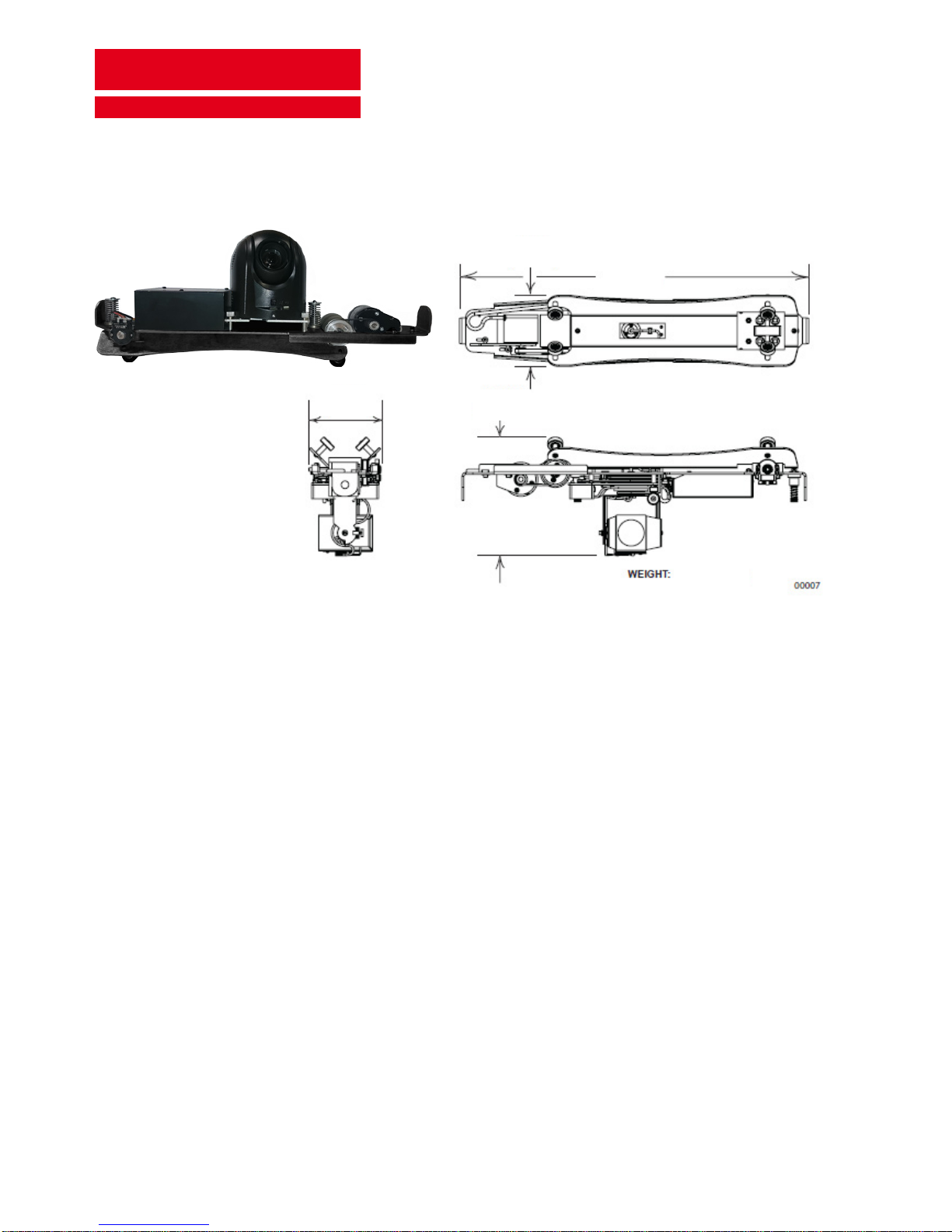
1.2.1 Physical dimensions of the camera carriage (see figure 1-1)
119 mm
575 mm
121 mm
194 mm
3.6 kg
Figure 1-1. CurveTrack® Camera Carriage
1.3 Units of measure
1.4 General Safety precautions
Dimensions and distances presented in this manual are expressed in metric units of measure.
If possible, avoid installing units in occupied buildings during regular business hours.
Installation area should be blocked o to keep bystanders safe from injury.
e track must be hung a minimum of 2.5 meters above the oor at its lowest point. e AC line providing power
to the Power Supply Assembly must be installed by a licensed electrician and must be in total conformance
with local electrical codes.

VIDEOSURVEILLANCE SYSTEMS
SENTRY
WAY
®
CT V2 001
Page 11 of 70
System Installation Guide
CAUTION
Socket outlets shall be installed nea r the equipment and be
readily accessible to the mains plug connections.
Use protective clothing such as a hard hat, safety shoes and heavy leather gloves when doing overhead
construction or erection. Wear approved safety glasses at all times.
Make certain you are grounded before handling electronic circuit boards or their components to prevent static
electricity from damaging sensitive electronic parts.
Keypad controllers used with this system must contain SELV circuits and be UL, CSA, CE, or ETL certied to
UL1950.
Never allow an inexperienced or untrained person to operate the control devices or make adjustments to the
unit.
Aer ensuring that the rail installation is straight, level and plumb, verify that all hardware has been securely
fastened.
Comply with all local codes regarding the use of ladders, lis and scaolding.
1.5 Responsabilities of the installer
While installing the CurveTrack® system, it is important that the installer understands that he /she is installing
a one-of-a-kind system. Installation must follow the guidelines and instructions presented in this manual in
order for the system to operate reliably providing years of good service with low maintenance.
Since the stability and reliability of the carriage depends entirely upon the rail, it is important to make sure
that the rail is installed straight, level and plumb. All associated components must be installed according to the
specications described in this manual and all applicable Sentryway eld bulletins and Tech Tips. Shortcuts
taken during installation with the intention of saving time or money can actually result in lost time and
increased expense if personnel must subsequently return to make corrections.
Every successful installation is the result of good, thorough planning. It is important that the lead installer
research all aspects of the installation before starting the actual, physical installation. is research includes:
reviewing construction drawings and Sentryway documentation, verifying that all materials required are at
the site, determining the needs of the installation team, and thoroughly reviewing the installation site itself. It
is also impor- tant that the customer, and the electrical contractor (if any), are involved in this planning stage.
VIDEOSURVEILLANCE SYSTEMS
SENTRY
WAY
®
CT V2 001
Page 12 of 70
System Installation Guide
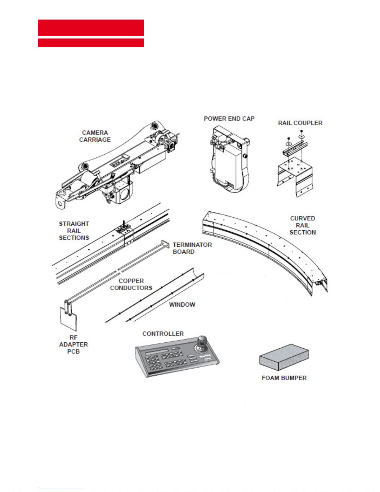
2. Identification of major components
2.1 System components (see figure 2-1)
00010
Figure 2-1. Major System Components

VIDEOSURVEILLANCE SYSTEMS
SENTRY
WAY
®
CT V2 001
Page 13 of 70
System Installation Guide
Carriage – e carriage is the wheeled assembly that travels the length of the system run. e carriage
provides mounting for the PTZ camera, control circuitry and the driving mechanism.
In manual mode, carriage movement and position are determined by the operator. In automatic mode,
the carriage “patrols” by continuously traversing the system run at a preset speed. A progammable tour
function makes it possible to have the cameras stopped and aimed at preset locations for specic lengths
of time, in any desired sequence, while patrolling.
Controller – e Controller is the device used by the operator of the system to send coded command
signals to the carriage.
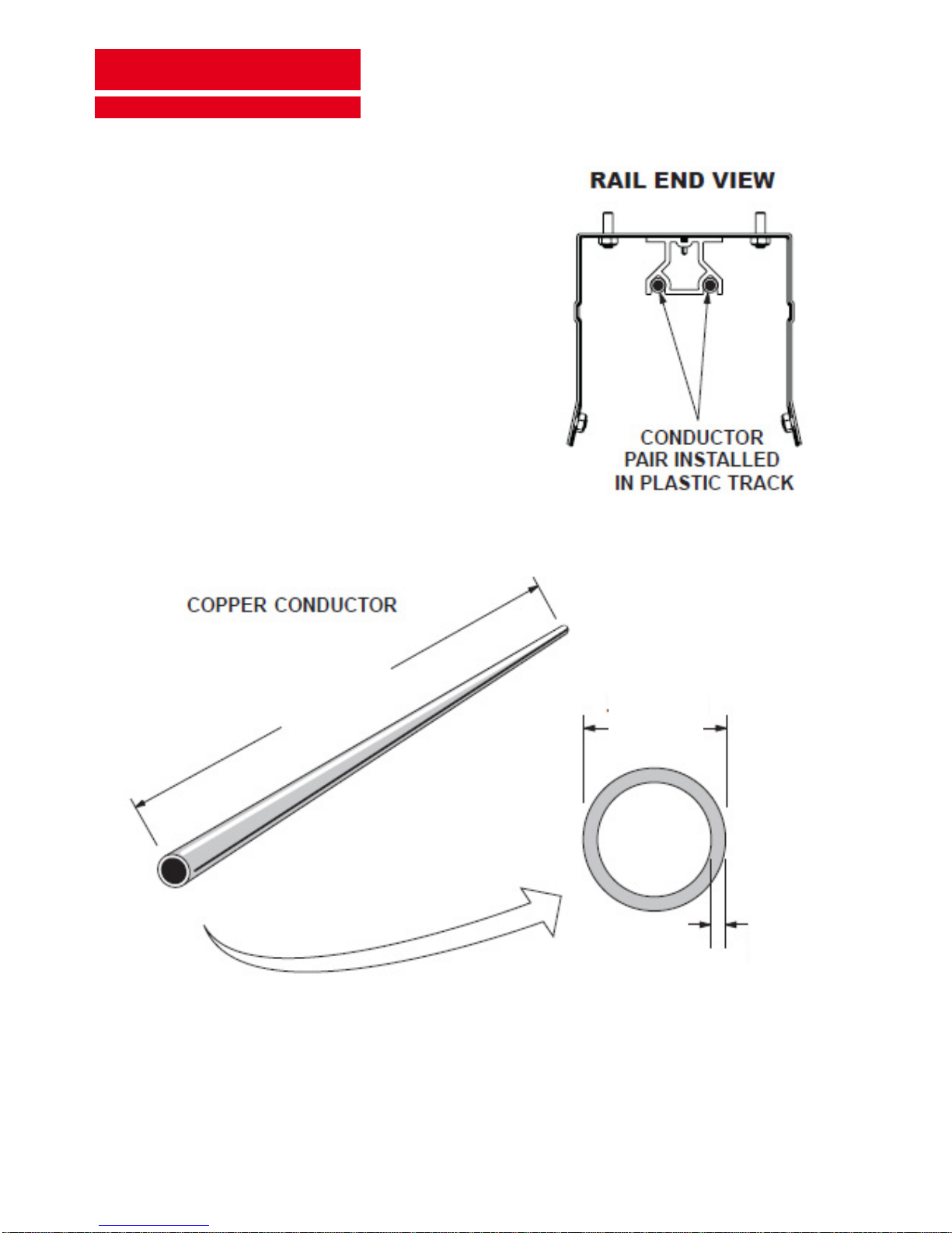
Copper Conductors – Two lengths of copper tubing, pressed into the plastic track portions of the rail
sections, extend the length of the system run. ese conductors carry control, power, and video signals.
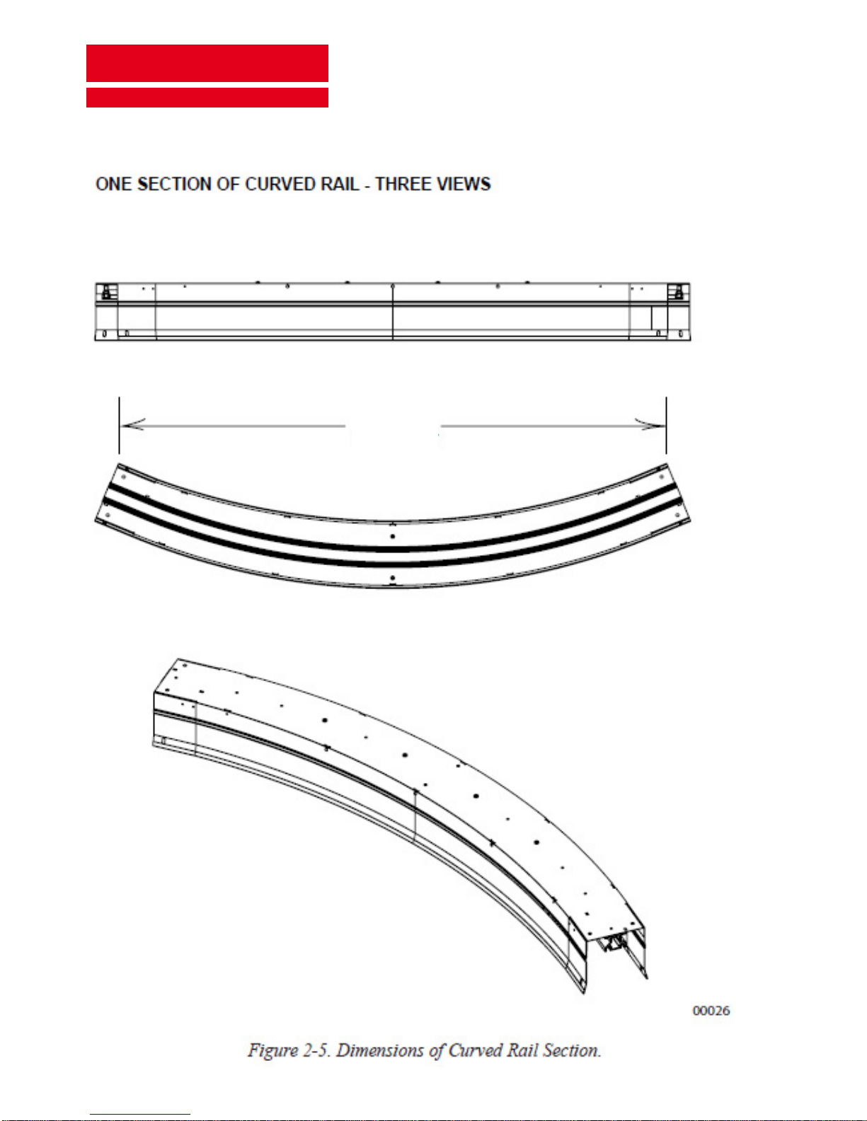
Rail Section – Each straight rail section is 2.5 meter long, three- sided, aluminum structure. Available
curved, 45-degree sections of rail can be combined to enable the system to be congured with 45, 90, or
180 degree bends and turns. Straight and curved rail sections are coupled together to form the system
run. All rail sections house the plastic track on which the camera carriage rolls. Continuous grooves in
the plastic track provide electrically isolated mounting for the copper conductors.
Rail Couplers – e rail couplers are shaped to snap over adjacent rail sections. readed studs on the
couplers engage holes pre-drilled in the rails. Nylon insert lock nuts secure the assembly together. e
short lengths of steel channel by which the rail is hung are secured to the top of each coupler.
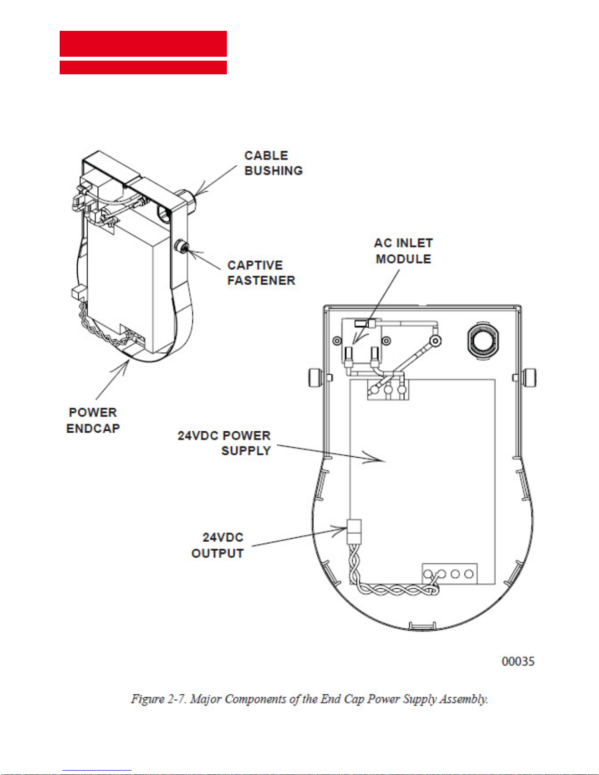
Power Supply Assembly (Power End Cap) – is enclosure connects to the power source and converts
(recties) AC to provide the necessary 24VDC power. e power supply is housed in the Power End Cap
at the service end of the system run. e power output cable from the power supply is plugged directly
into the RF Adapter PCB. A relay board is included to switch the DC output from a remote location.
RF Adapter Board – e RF Adapter board, located at the same end of the system run as the Power
Supply Assembly, acts as an interface and relays video, power, and control signals between the Power
Supply Assembly and Video Modem and the copper conductors.
System Run – e term system run refers to a single assembly of multiple rail sections joined together.
Only one camera carriage may operate within each system run, and each system run must be operated
from its own Power Supply Assembly. An installation site consists of one or more system runs.
Terminator Board – Provides electrical termination of the two copper conductors at the end of the system
run opposite the RF Adapter board.
Windows – e window material, delivered to the job site in rolls, is a plastic material with a mirror
nish. e windows are secured to the rail sections using small clips that pass through slots punched in
the window material and engage a rib on the edge of the rail housing.
Foam Bumper – A foam bumper is installed at each end of the system run to protect the carriage in the
event it strikes the end of the rail.
2.1.1
2.1.2
2.1.3
2.1.4
2.1.5
2.1.6
2.1.7
2.1.8
2.1.9
2.1.10
2.1.11
VIDEOSURVEILLANCE SYSTEMS
SENTRY
WAY
®
CT V2 001
Page 14 of 70
System Installation Guide
2.2 Rail components
WEIGHT: 1041 g
Weight specied is for each single 5 m section of copper
conductor. Remember that two such conductors, mounted
parallel to each other, as shown to the right, are pressed
into the plastic track and run the entire length of the rail.
e copper conductor tubes are 9.5mm OUTSIDE diameter by
5 meters long and have a wall thickness of 0.762mm.
00020
Figure 2-3. Copper Conductors.
5 m
0.762 mm
9.5 mm

VIDEOSURVEILLANCE SYSTEMS
SENTRY
WAY
®
CT V2 001
Page 15 of 70
System Installation Guide
2.5 m
165.5 mm
150 mm
255 mm
185 mm
VIDEOSURVEILLANCE SYSTEMS
SENTRY
WAY
®
CT V2 001
Page 16 of 70
System Installation Guide
1.35 m
VIDEOSURVEILLANCE SYSTEMS
SENTRY
WAY
®
CT V2 001
Page 17 of 70
System Installation Guide
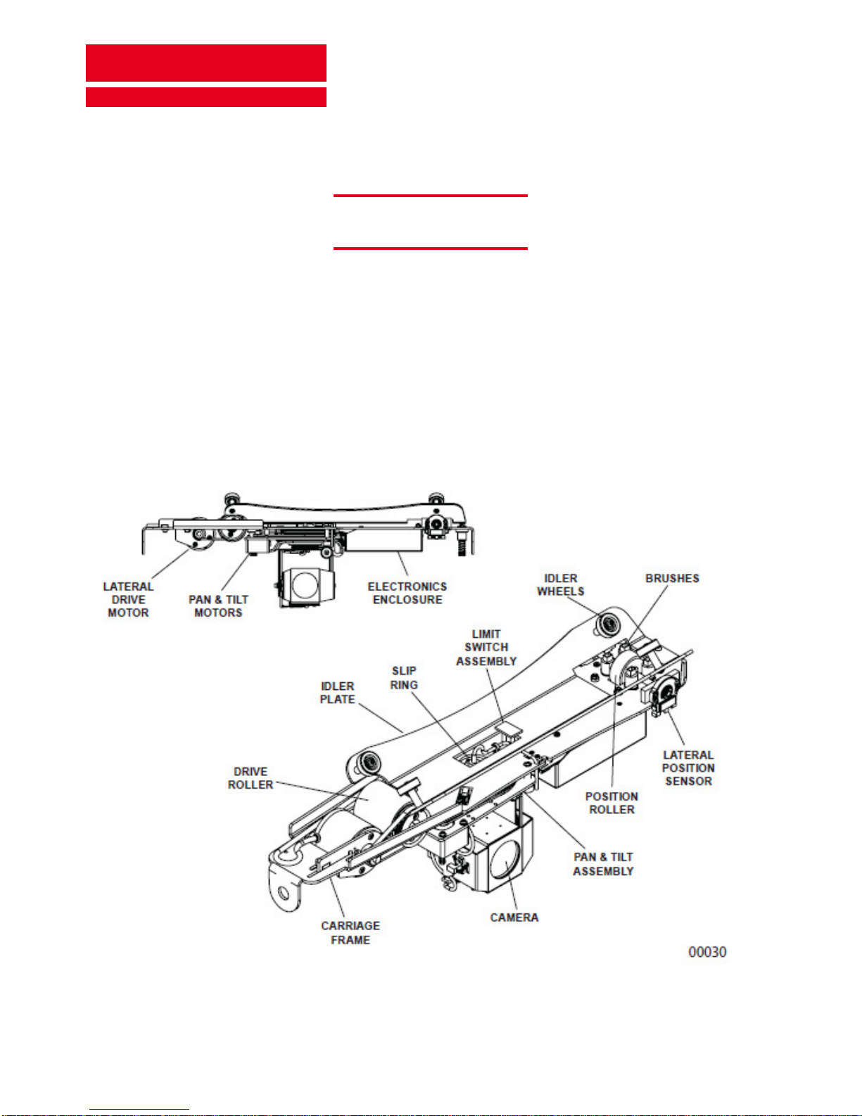
2.3 Carriage components (See figure 2-6)
Any time you li the carriage, it must be supported with both hands. Li
the carriage by the frame and idler plate ONLY! Do not apply any liing
forces to the pan and tilt assembly or to the electronics enclosure.
Do not rest the carriage on the brushes, pan and tilt assembly, or slip ring.
If the carriage must be rested on a hard surface, lay it GENTLY on its side.
Alternatively, lean the carriage on end against the wall.
CAUTION
Figure 2-6. CurveTrack® Camera Carriage
VIDEOSURVEILLANCE SYSTEMS
SENTRY
WAY
®
CT V2 001
Page 18 of 70
System Installation Guide
2.4 Power supply assembly (Power End) components (See figure 2-7)
VIDEOSURVEILLANCE SYSTEMS
SENTRY
WAY
®
CT V2 001
Page 19 of 70
System Installation Guide
3. Site evaluation and planning
3.1 Overview
A good installation is always preceded by good preliminary planning. A comprehensive site survey and a set
of oor plans are valuable assets for system planning. It is essential to determine the location best suited for
the system run(s), and to identify the type of ceiling or roof structure from which it will be suspended, prior to
specifying the required mounting materials. Proper planning will ensure that you have an adequate supply of
mounting materials on hand, before starting the installation, to minimize delays.
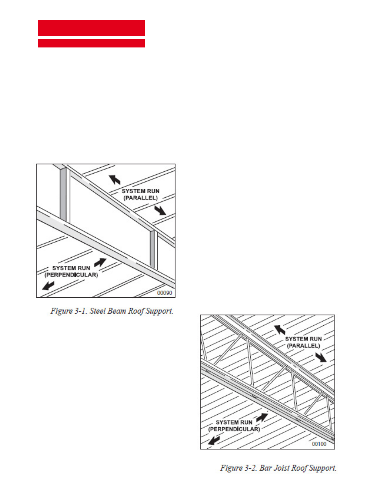
A system run can be installed either in parallel with, or perpendicular to, bar joists, steel beams, preformed
concrete beams, or C– Purlin beams. A at corrugated
steel roof is yet another possibility which will require its
own alternative method of installation.
e instructions in Sections 3 and 4 detail specic
installation methods suitable for the majority of roof and
ceiling types.
Figure 3-1 illustrates a typical steel beam type of roof
support structure. Since spacing between beams and
the distance between the beams and the oor can vary
greatly, close attention to these variables is important
when planning for sucient mounting material. Read the
following installation instructions rst before deciding
on the best mounting method and materials to use.
Figure 3-2 illustrates a typical bar joist type of roof
support structure. Mounting to this type of support will
not require drilling into the bar joist

VIDEOSURVEILLANCE SYSTEMS
SENTRY
WAY
®
CT V2 001
Page 20 of 70
System Installation Guide
Figure 3-3 illustrates a typical type of C – Purlin roof
support structure. Special clamps, which require no
drilling, are available from STC.
Figure 3-4 illustrates a typical reinforced concrete
type of roof support structure. is type of
construction will require drilling into the concrete
and the use of bolt anchors or the use of special
beam clamps. Installing into at concrete will
always require drilling and inserting bolt anchors.
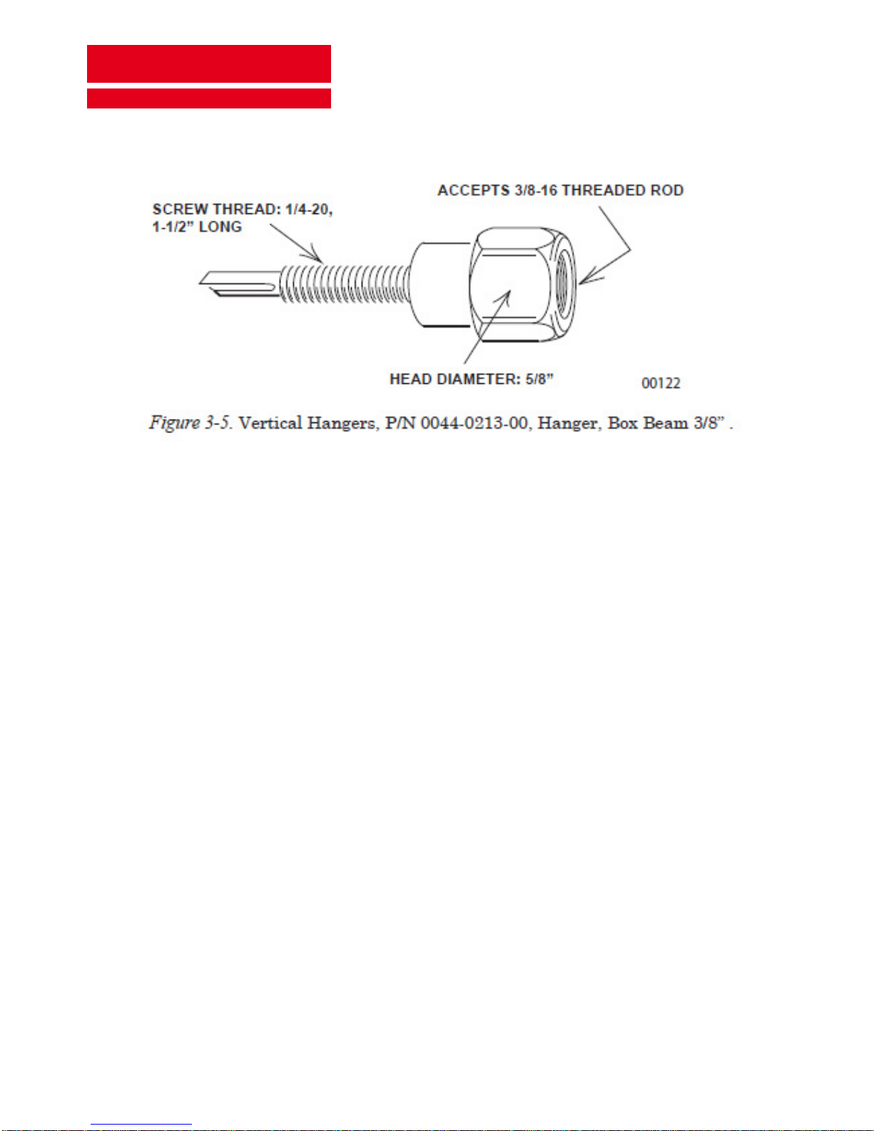
ere are some buildings, that have at corrugated steel roofs which may or may not have additional support
structures. If a steel roof has a thickness between 0.8 mm) and 4.76 mm, it is possible to use Vertical Hangers
(P/N 0044-0213-00, HANGER, BOX BEAM 3/8” ) to hang the rail. (See Figure 3-5.) is hanger has a 38 mm
long mounting sha and a M10 x1.5 female thread to accept the threaded rod end. One advantage to using
Vertical Hangers is that there are more options available when orienting the system run. If there is a support
structure to contend with, the run can be oriented in a parallel or perpendicular direction without regard to
the structure. Hangers can be installed wherever necessary. As with all installations, rst establish a centerline
for the system run.
VIDEOSURVEILLANCE SYSTEMS
SENTRY
WAY
®
CT V2 001
Page 21 of 70
System Installation Guide
Locate two rod drops to align with the rst and last rail coupler mounting channel. Locate the remaining rod
drops along the centerline and placed no more than 5 meters (the length of two rail sections) apart. Drill a
mounting hole for each hanger. Hole diameter should equal the thickness of the steel, e.g., 0.8 mm diameter hole
for 20 gauge (.036”) steel, and 4.76 mm diameter hole for steel that is 3/16” thick (maximum). e remainder
of the hanging procedure is the same as it would be when dealing with any roof support structure.
Installation will progress smoothly if work can be scheduled for when there is little or no outside activity in
the work area. Reserve special equipment that may be needed, such as lis, scaolding, etc., well in advance.
Schedule a qualied electrician well in advance of when you anticipate needing his / her services.
Identify a straight, level, and unobstructed area for installing the entire system run. Refer to the engineering
drawings for your particular installation to determine the service end of the system run. e Power End Cap
(or Alternate Power Supply Assembly, as applicable) and the RF Adapter will need to be located at the service
end of the run. Carefully inspect the area above and near the proposed system run for physical obstructions
such as drop ceilings, lighting xtures, water pipes, electrical conduit, HVAC duct work, etc., which might
have to be relocated or would force another location for the system run.
3.2 Setting up a schedule
3.3 Planning installation of the system run

VIDEOSURVEILLANCE SYSTEMS
SENTRY
WAY
®
CT V2 001
Page 22 of 70
System Installation Guide
Establish a system height (distance from the oor to the system run) that allows adequate clearance from
obstructions and maximizes the desired viewing area. e rail must be hung a minimum of 2.5 meters above
the oor at its lowest point. Verify at least 0.3 meter of clearance, from the top of the rail section down, over
the entire proposed system run.
NOTE
Local codes may dictate dierent specic
distance requirements .
Power for the CurveTrack® systems should be controlled by dedicated circuit breakers. ere should be no
more than four CurveTrack® Power Supplies (i.e. four system runs) per circuit breaker.
Ensure that oor level obstructions to li equipment, ladders, etc. are
accounted for and can be worked around to maintain a safe environment for
installation workers and bystanders. Be especially aware of the potential hazard
of falling materials, tools and debris as well as potential trip hazards, including
power cords, in areas below the installation zone.
DANGER
All CurveTrack® equipment and installation materials that are at the site of the installation must be inspected
for damage. All Claims for losses, or damage to the system in transit, must be made with the carrier. Packing slip
documentation should be checked carefully against material received to ensure that everything that is needed
has arrived. It is suggested that before the actual construction begins, the installation team do a complete
inventory while the lead installer reviews the site. Any shortages in parts or materials must be reported as soon
as possible so that corrections can be made in a timely fashion.
Aer inspection, return all materials to their shipping containers to protect them until they are used. Designate
a specic storage area in a protected place to prevent accidental damage, especially to delicate electronic parts
and the easily – damaged windows.
3.4 Material inspection and inventory
3.5 Material storage

VIDEOSURVEILLANCE SYSTEMS
SENTRY
WAY
®
CT V2 001
Page 23 of 70
System Installation Guide
3.6 Recommended tool list
is list includes tools required to install the entire CurveTrack®™ system.
Safety Equipment
Safety Glasses
First Aid Kit
Hard Hats
Work Gloves
Hearing Protection
Cutting & Shaping Tools
Portable Band Saw
Power Drill
(with hammer capability)
Portable Drill Driver
Tubing Cutter/ Reamer
Utility Knife
Wire Strippers
CAT 5 Crimper/Stripper
Diagonal Cutters
File
Hammer
Measuring Devices
Surveyor’s Tape Measure
Multi – Meter
Tape Measure
String Line
Scratch Awl
I-beam level
120 cm Level
Torpedo Level
Plumb Bob
Fastening Tools
Straight Blade Screwdriver
Phillips Screwdriver
Tweaker Screwdriver
Crescent Wrench
Nut Drivers
Hex - Key Wrenches
Drive Ratchets
Socket wrenches
Combination wrenches
Drill Bits
One Set, High Speed
One Hole Saw, 22mm
Soldering Supplies
Propane or MAPP Torch
Solder
Flux
Emery Cloth
Torch Heads
Cleaning Supplies
Paper Towels
Clean, Lint– free Rags
Denatured Alcohol
Alkaline-based cleaner
(not Ammonia)
Non-abrasive Cleaning Pads
Miscellaneous
Drop Light
Flashlight
Duct Tape
Electrician’s Tape
Tool Pouch
Silicone Adhesive
One set of Two– Way Radios

VIDEOSURVEILLANCE SYSTEMS
SENTRY
WAY
®
CT V2 001
Page 24 of 70
System Installation Guide
4. Support structure installation
4.1 General
4.2 Fastening Support Hardware to Bar Joists - Perpendicular
readed rods (hangers) must be provided for attachment to the end couplers of both the rst and last rail
section in every system run. One threaded rod is to be located at least at every second rail section coupler.
When completed, there should never be a span of more than two rail sections between support rods.
Additional B-channel, installed spanning two rail couplers, may be added along the centerline of the rail to
provide mounting points for extra threaded rods, guy wires, etc. or to circumvent overhead obstructions.
Figure 4-1 illustrates a typical installation of the CurveTrack® rail to bar joist ceiling
construction using precut lengths of M10 threaded rod. See paragraph 3.3, Planning Installation of the System Run, to determine
hanging height, and paragraph 5.2, Cutting the readed Rod, before cutting the threaded rod.
Locate the approximate centerline of the system run and install a taut string line over the full
length of the system run. Install the string as high as possible making certain it remains clear of
all obstructions.
read a M10 x 1.5 hex nut (1, Fig.4-1), M10 spring lock washer (2, Fig. 4-1) and a square washer
(3, Fig. 4-1) onto one end of each threaded rod (4, Fig. 4-1) so that 100mm, plus the height of the
bar joist angle, is extending beyond the square washer.
Insert the end of the rod assembly between the bottom angles of the bar joist and fasten loosely
with a square washer (5, Fig. 4-1), lock washer (6, Fig. 4-1), and hex nut (7, Fig. 4-1). Do not
tighten until the associated track section is hung and aligned.
4.2.1
4.2.2
4.2.3

VIDEOSURVEILLANCE SYSTEMS
SENTRY
WAY
®
CT V2 001
Page 25 of 70
System Installation Guide
4.3 Fastening Support Hardware to Bar Joists - Parallel
When the installation requires the system run to be parallel to the bar joists, metal channel is used as a spanner
to bridge the bar joists at each mounting point of the system run as shown in Figure 4-2.
Lengths of channel should be cut 0.3 meter longer than the distance between the bar joists to allow for mounting
hardware.
Install the rst and the last channels on the system run. Determine the centerline of the system
run and mark it on each channel.
Place channels on bar joists every 4.8 meters so that there is one channel for each threaded rod
assembly and that each channel is placed at the same location, relative to the string
line (refer to paragraph 4.1).
Center channel (1, Fig. 4-2) over bar joist bottom angles with the open side of the channel facing
down. Slide M10 channel lock nuts (2, Fig. 4-2) into each end of the channel until they are
centered between joist angles.
Assemble M10 x 1.5 hex nuts (3, Fig. 4-2), M10 spring lock washers (4, Fig. 4-2)
and square washers (5, Fig. 4-2) onto two M10 x 1.5 x 150mm hex head cap screws (6, Fig 4-2).
Insert screw end between bar joist angles and thread into Twirl nuts. Do not tighten screws
securely until the rail section is hung and aligned.
4.3.1
4.3.2
4.3.3
4.3.4

VIDEOSURVEILLANCE SYSTEMS
SENTRY
WAY
®
CT V2 001
Page 26 of 70
System Installation Guide
4.4 Fastening Support Hardware to Steel Beams - Perpendicular
Figure 4-3 illustrates the use of Beam Clamps for attaching threaded rod to steel beam ceiling construction.
Locate the approximate center line of the system run. Insert a locking strap (1, Fig. 4-3) into
beam clamp (2, Fig. 4-3) and center the rst and last beam clamp on the centerline.
Install a taut string line the full length of the system run. Keep the string line in place for use as
a plumb line reference when aligning the system run.
Secure beam clamps to beam with square head, cone point set screws (3, Fig. 4-3) and M10 x 1.5
lock nuts (4, Fig. 4-3). Assemble two M10 x1.5 hex nuts (5, Fig. 4-3), one M10 spring lock washer
(6, Fig. 4-3) and a swivel (7, Fig. 4-3) on the end of the threaded rod (8, Fig. 4-3) as shown.
Insert plastic bushings (9, Fig. 4-3) into pivot holes on each side of the beam clamps. Position
swivels on threaded rod assemblies over the plastic bushings and secure with hex bolts (10, Fig.
4-3) and elastic lock nuts (11, Fig. 4-3). Tighten elastic lock nuts lightly so that rod assemblies
can swivel on beam clamps. When the
position of the clamps are nalized,
bend locking straps over the far
corner of the steel beams and tighten
set screws and locking nuts securely.
Observe that in the illustration, the
locking strap (1, Fig. 4-3) is shown
bent into the locking position.
4.4.1
4.4.2
4.4.3
4.4.4

VIDEOSURVEILLANCE SYSTEMS
SENTRY
WAY
®
CT V2 001
Page 27 of 70
System Installation Guide
4.5 Fastening Support Hardware to Steel Beams - Parallel
When the installation requires the system run to be parallel to the steel beams, channel is used as a spine to
bridge the beams at the mounting point for each rail section as shown in Figure 4-4. Lengths of channel should
be cut 0.3 meter longer than the outside distance between the beams to allow for mounting hardware.
Position each channel (1, Fig. 4-4) with open side down. Place U – bolts (2, Fig. 4-4) around
channel, facing up, and through beam clamps (3, Fig. 4-4) and M10 spring lock washers (4, Fig.
4-4). read M10 x 1.5 hex nuts (5, Fig. 4-4) loosely to each end. ese assemblies can be made
in the quantity needed for each system run before attaching to bottom of beams.
Raise and center channel assemblies in the desired locations on the beams, and slide lamps and
U–bolts rmly against the inside legs of the beams. Check to ensure that the distance between
channels coincides with the desired location of threaded rod hangers.Verify approximate
“squareness” of channels to the beams, and then tighten hex nuts securely.
4.5.1
4.5.2

VIDEOSURVEILLANCE SYSTEMS
SENTRY
WAY
®
CT V2 001
Page 28 of 70
System Installation Guide
4.6 Fastening Support Hardware to C–Purlin Beams - Perpendicular
Figure 4-5 illustrates the use of beam clamps for attaching threaded rod to C–Purlin beam
construction.
Mark the centerline of the system run on beams.
Insert locking straps (1, Fig. 4-5) into slots in each beam clamp (2, Fig. 4-5) and
then place
each beam clamp over the open lower edge of the beam.
4.6.1
4.6.2
Secure clamps to beams with square head cone point set screws (3, Fig. 4-5) and M10 x 1.5 hex
nuts (4, Fig. 4-5). Observe that, in the illustration, the locking strap (1, Fig. 4-5) is shown bent
into the locking position.
Assemble two M10 x 1.5 hex nuts (5, Fig. 4-5), one spring lock washer (6, Fig. 4-5) and a swivel
(7, Fig. 4-5) on one end of each pre-cut threaded rod (8, Fig. 4-5).
4.6.1
4.6.2

VIDEOSURVEILLANCE SYSTEMS
SENTRY
WAY
®
CT V2 001
Page 29 of 70
System Installation Guide
CAUTION
It is important to remember that, when mounting the support
structure to slanted ceilings, the ceiling pitch must be taken into
account when measuring and cutting lengths of threaded rod.
Insert plastic bushings (9, Fig. 4-5) into pivot holes on each side of beam clamps. Position
swivels of threaded rod assemblies over plastic bushings and secure with hex bolts (10, Fig.
4-5) and elastic lock nuts (11, Fig. 4-5). Tighten elastic lock nuts lightly so that rod assemblies
can swivel on beam clamps. When position of clamps is nalized, bend locking straps over the
back side of beams and tighten set screws and lock nuts securely.
Locate the approximate centerline of the system run and locate the rst and last beam clamp
on the centerline.
Install a taut string line the full length of the system run so that it is just o of the outside edge
of the clamp. Keep the string line in place for use as a plumb line reference when aligning the
system run.
4.6.5
4.6.6
4.6.7

VIDEOSURVEILLANCE SYSTEMS
SENTRY
WAY
®
CT V2 001
Page 30 of 70
System Installation Guide
4.7 Fastening Support Hardware to C–Purlin Beams - Parallel
When the installation requires the system run to be parallel to the C– Purlin beams, channel is used as a spine
to bridge the beams at each mounting point of a rail section as shown in Figure 4-6. Lengths of channel should
be cut 0.3 meter longer than the outside distance between beams to allow for mounting hardware.
Position each channel (1, Fig. 4-6) with the open side down. Place U–bolts (2,Fig. 4-6 ) around
channel facing up and through beam clamps (3, Fig. 4-6) (bent edges both facing the same
direction) and fasten with M10 spring lock washers (4, Fig. 4-6) and M10 x 1.5 hex nuts (5,
Fig. 4-6).
Raise and center channel assemblies at the desired position against beams. Hook bent edge
of beam clamps over open edge of C – Purlin beams. Check to ensure that distance between
channels coincides with the desired location of threaded rod hangers. Verify that the channels
are approximately square to the beams, and then tighten the hex nuts securely.
Install a taut string line, running the full length of the system run, 100mm to one side of
where the centerline of the rail sections will be located. Keep the string line in place to use as
a plumb line reference when aligning rail sections later.
4.7.1
4.7.2
4.7.3

VIDEOSURVEILLANCE SYSTEMS
SENTRY
WAY
®
CT V2 001
Page 31 of 70
System Installation Guide
4.8 Fastening Support Hardware to Flush Concrete - Parallel and
Perpendicular
Installing support structure to concrete presents both special considerations and limitations as well as some
advantages. An advantage of mounting in concrete is the unrestricted positioning of the locations for threaded
rod drops that allow the support structure to be positioned at the optimum location (see Figure 4-7). e
short, 355mm channel must be placed in accurate alignment on the system run centerline if you choose to
mount the channel parallel to the system rails. is provides signicant room for adjustment of the rod drops
to connect with the mounting points on the rail connectors.
ere is less height adjustment available than with some other types of construction due to the ush mounting
of the channel. Maximum height adjustment will be limited to 150mm in the turnbuckles, which must be used
with this type of construction.
Establish the location of the system run and, using a chalk or snap line, mark the centerline of
the run. Center the channel on a point where a rod drop will be located. Using the channel as
a template, mark, centerpunch, and drill additional holes centered in the slotted holes on each
end of the channel. Centerpunch and, using a carbide – tipped concrete bit, drill the two holes
in the concrete on the centerline.
Proceed to mark and drill sets of holes down the centerline at intervals that match the
desired location of threaded rod drops. Most threaded rod drops on straight sections of rail
will be 2.5 meters apart.
4.8.1
4.8.2
4.8.3
4.8.4
NOTE
e depth and diameter of the holes drilled will be determined by the
concrete anchors specied in the Bill Of Materials. Fastening hardware
can also vary, depending upon the installation.
Install concrete anchors (1, Fig. 4-7) in each drilled hole, and set them with a sharp hammer
blow.
Mount 355mm sections of channel (2, Fig. 4-7) to the concrete, using bolts (3, Fig. 4-7), spring
lock washers (4, Fig. 4-7) and fender washers (5, Fig. 4-7) through the end and center slots
of the channel and into the concrete anchors.

VIDEOSURVEILLANCE SYSTEMS
SENTRY
WAY
®
CT V2 001
Page 32 of 70
System Installation Guide
4.8.5
4.8.6
4.8.7
Slide a M10 channel lock nut (6, Fig. 4-7) into the channel.
Establish the length for the threaded rod (7, Fig. 4-7) by measuring the distance from the concrete
to the top of the rail section when the rail is at the desired height above the oor. Subtract 200mm
for the turnbuckle adjustment portion. Cut the rod.
read M10 x 1.5 hex nuts (8, Fig. 4-7) on one end of the threaded rods. Install M10 spring lock
washers (9, Fig. 4-7) and square washers (10, Fig. 4-7) on the threaded rod.Screw this end into
the Twirl nut in the channel until the threaded rod almost bottoms out in the
channel, and then fasten hex nut nger tight. When you are ready to attach the threaded rods to
the rail, refer to paragraph 6.4 and 6.5.

VIDEOSURVEILLANCE SYSTEMS
SENTRY
WAY
®
CT V2 001
Page 33 of 70
System Installation Guide
4.9 Fastening Support Hardware to Reinforced Concrete Beams
Figure 4-8 illustrates the attachment of channel to one type of reinforced concrete. If the system run is parallel
to beams (as shown), concrete anchors and lag bolts are used on each end of the channel spanning two beams.
is type of installation uses threaded rod assemblies to hang the rail.
4.9.1
4.9.2
4.9.3
4.9.4
Establish the location of the rst attachment hole. Place a carpenter’s square against the concrete
beam and squarely mark the location of the attaching holes in the adjoining beams. Use a length
of channel as a template for hole spacing.
Using a carbide– tipped concrete bit, drill holes at each location. e depth and diameter of
the holes drilled will be determined by the concrete anchors specied in the Bill Of Materials.
Fastening hardware can also vary, depending upon the installation. Drive anchors (1, Fig. 4-8)
into each hole.
Position channel (2, Fig. 4-8) as shown, and fasten with at washers (3, Fig.4-8), lock washers (4,
Fig. 4-8) and lag screws (5, Fig. 4-8).
Proceed to mark and drill sets of holes down the length of the system run. When ready to attach
threaded rod to the rail sections, refer to Figure 5-2.
When mounting to reinforced concrete
beams for perpendicular system runs,
installation will be the same as for ush
mount concrete. (See Figure 4-7.)
Turnbuckles must be used between the
threaded rod and the rail sections as shown
in Figure 5-3.
NOTE

VIDEOSURVEILLANCE SYSTEMS
SENTRY
WAY
®
CT V2 001
Page 34 of 70
System Installation Guide
5. Threaded rod installation
5.1 General
5.2 Cutting the threaded rod
Each rail section is suspended from the supporting structure using M10 threaded rod. Refer to Site Evaluation
and Planning, paragraph 3, and, more specically, Planning Installation of the System Run, paragraph 3.3,
for suggestions on determining drop distance.
e threaded rod is delivered to the job site in 3 meter lengths. Each rod must be cut to the required length.
Figure 5-1 illustrates the methods used to determine the proper length for the rods. Adding an additional
100mm to each rod will allow for alignment adjustments. Installations that require swivels on the beam
clamps should not add the 100mm to the threaded rod measurement, because all adjustment must be made
using the turnbuckles.

VIDEOSURVEILLANCE SYSTEMS
SENTRY
WAY
®
CT V2 001
Page 35 of 70
System Installation Guide
Cut two equal lengths of rod for the rst two rail sections in the system run, and cut at least one more length
for each remaining rail section. On C– Purlin and steel beam perpendicular installations that allow the beam
clamps to be mounted in a vertical position, it is possible to run the threaded rod up and through the beam
clamp, eliminating the swivel. Measure to the top of the clamp for this type of installation. Subtract 200mm
from the total length of the threaded rod when using turnbuckles to adjust for the desired length.

VIDEOSURVEILLANCE SYSTEMS
SENTRY
WAY
®
CT V2 001
Page 36 of 70
System Installation Guide
5.3 Installing threaded rod in channel for parallel runs
Figure 5-2 illustrates a typical threaded rod installation where there are no turnbuckles used. Without
turnbuckles, all height adjustments must be made from above the pre- installed support channel. If the threaded
rod exceeds 1.25 meters in length, it is dicult to see leveling devices placed on the track. erefore, when the
overall drop length exceeds 1.25 meters, or, when attaching rods to ush ceiling mounts, or Vertical Hangers,
install turnbuckles on the lower end of the threaded rod assemblies to facilitate adjustment. Refer to paragraph
5.4, Installing Turnbuckles on readed Rods.
Fasteners shown on the lower end of the threaded rod
may be pre-assembled and the rail section mounting
channels slid onto the Twirl nuts, or, the Twirl nuts may
be pre–installed in the rail mounting channels. In this
way, as the rails are lied into position, the threaded rods
can be turned into the Twirl nuts.
NOTE
5.3.1
5.3.2
5.3.3
5.3.4
Install two rods to suspend the rst two rail sections, and install at least one rod for each additional
pair of rail sections. It is not necessary to provide a dedicated rod drop for every section. It is
sucient to provide one rod drop for every second rail section. In this way, rail sections can be
assembled and hung in pairs. Distance between threaded rods, or drops, cannot exceed 5meters
(the combined length of two rail sections).
read M10 x 1.5 hex nuts (1, Fig. 5-2) on M10 threaded rods (2, Fig. 5-2) 165mm from the end.
Install M10 spring lock washers (3, Fig. 5-2) and square washers (4,Fig. 5-2) on the rods.
With the aid of a step ladder or li, insert the rod assemblies through the appropriate slotted
holes in the pre – installed channel (5, Fig. 5-2). Secure with at fender washers (6, Fig. 5-2), M10
spring lock washers (7, Fig. 5-2) and M10 x 1.5 hex nuts (8, Fig. 5-2).
read M10 x 1.5 hex nuts (9, Fig. 5-2) on the bottom of the threaded rod at 25mm
from the end. Install M10 spring lock washers (10, Fig.5-2), M10 square washers (11, Fig. 5-2),
and Twirl nuts (M10 channel lock nuts) (12, Fig. 5-2).

VIDEOSURVEILLANCE SYSTEMS
SENTRY
WAY
®
CT V2 001
Page 37 of 70
System Installation Guide
Leave fasteners at the top of the rods loose so that rods
can be turned into Twirl nuts i f you intend to pre–
install Twirl nuts into rail section mounting channels.
e hardware on each threaded rod is to be tightened
later as the corresponding rail sections are hung and
properly aligned.
NOTE

VIDEOSURVEILLANCE SYSTEMS
SENTRY
WAY
®
CT V2 001
Page 38 of 70
System Installation Guide
5.4 Installing turnbuckles threaded rods
Figure 5-3 illustrates the recommended hardware necessary for attaching turnbuckles between the threaded
rod assemblies and the rail sections. Turnbuckles may be used on all installations to aid in rail alignment, but
are recommended especially for threaded rod drops exceeding 1.25 meters.
5.4.1
5.4.2
5.4.3
5.4.4
Insert a M10 x 1.5, 125mm square head bolt (1, Fig. 5-3) through small O.D. at washer (2, Fig.
5-3) and into the non – threaded hole in turnbuckle (3, Fig. 5-3).
read M10 x 1.5 hex nut (4, Fig. 5-3), M10 spring lock washer (5, Fig. 5-3) and
turnbuckle (3, Fig. 5-3) onto bottom ends of threaded rod (6, Fig. 5-3) so that the threads extend
about halfway into the turnbuckles.
Install M10 spring lock washer (7, Fig. 5-3) and two M10 x 1.5 hex nuts (8, Fig.
5-3) on bolts (1, Fig. 5-3) so that lower hex nuts are 25mm from the end.
Install M10 spring lock washer (9, Fig. 5-3), M10 at washer (10, Fig. 5-3) and M10 channel lock
nut (11, Fig. 5-3).
Twirl nuts can also be inserted into rail section
mounting channels before or aer raising rails into
position. Turnbuckle bolts can then be turned into the
Twirl nuts.
NOTE

VIDEOSURVEILLANCE SYSTEMS
SENTRY
WAY
®
CT V2 001
Page 39 of 70
System Installation Guide

VIDEOSURVEILLANCE SYSTEMS
SENTRY
WAY
®
CT V2 001
Page 40 of 70
System Installation Guide
6. Rail section installation
6.1 Rail section inspection
6.2 Rail section cleaning
6.3 Rail section preparation
Each rail section is suspended from the supporting structure using M10 threaded rod. Refer to Site Evaluation
and Planning, paragraph 3, and, more specically, Planning Installation of the System Run, paragraph 3.3,
for suggestions on determining drop distance.
Clean interior surfaces of the rail section, as required, with a lint– free rag, slightly
dampened with
plain water. Do not use solvents or cleaning solutions of any kind.
6.1.1
6.1.2
6.1.3
6.1.4
Inspect all rail sections for obvious defects.
Working at oor level, take the rst two rail sections to be hung, and butt them up against each
other end – to–end. Check alignment of corresponding mating surfaces, especially in the area
where the carriage wheels will cross the seam.
Inspect the alignment of the plastic tracks inside the rail sections where they will be joined. If
alignment is poor, try another rail section to nd a better match.
Fasten the two rail sections together with a rail coupler. See Figure 6-1. Repeat the two previous
steps for each pair of adjoining rail sections. A rail coupler must also be installed at each end
of the system run to provide both hanging points for the ends of the system run and fastening
points for the bumper stops and the end caps.
Use extreme care when entering this phase of the installation. Handling heavy or
awkward objects at varying heights above oor level can be hazardous to personnel
and equipment.
One of the most eective ways to reduce installation time is to run a string line that
extends just beyond each end of the planned system run. Locate it so that it will
be level and parallel to the top edge of the rail sections. Use the string to help in
aligning the system run.
NOTE
DANGER

VIDEOSURVEILLANCE SYSTEMS
SENTRY
WAY
®
CT V2 001
Page 41 of 70
System Installation Guide
CAUTION
Raising and attaching rail sections require a minimum of two persons.
At exceptionally high installations, or when there are large, immovable
objects beneath the erection site, power lis or scaolding may be required.
6.3.1
6.3.2
Position two step ladders of sucient height below the intended location of the rst two rail
sections.
Li the rail sections by holding each end of the assembly rmly in a horizontal position and
“walking” it up to the attachment height.

VIDEOSURVEILLANCE SYSTEMS
SENTRY
WAY
®
CT V2 001
Page 42 of 70
System Installation Guide
CAUTION
Raising and attaching rail sections require a minimum of two persons.
At exceptionally high installations, or when there are large, immovable
objects beneath the erection site, power lis or scaolding may be required.
6.3.3
6.3.4
6.3.5
6.3.6
Connect threaded rods to rail sections. Refer to paragraph 6.4 or 6.5, as applicable.
Check alignment of rail sections. Refer to paragraph 6.6.
Raise the next pair of rail sections to the far end of the rst or previous rail sections, making sure
that they are kept horizontal. As the installer holds the mating end of the next pair of rail sections
in position, snap a rail section coupler over the adjoining rail sections and secure it using the
supplied nylon insert lock nuts
Tighten the nylon insert lock nuts securing each rail section coupler.
6.4 Connecting Rail section to threaded rod assemblies - Method 1
NOTE
Guy wires (refer to paragraph 6-7) are always required
in order to stabilize the system run. A 7.5m rail will need
two guy wires at each end and another pair in the center.
Two more guy wires will be needed for each additional 3m
of rail. To accommodate fastening the guy wires, insert the
associated hardware in the rails a t t h i s po in t i n t h e
installation
If M10 channel lock nuts (11, Fig. 5-3) or (12, Fig. 5-2) have been attached to threaded rods or turnbuckles,
they must be carefully slid into the mounting channels of the rail section couplers. Do not exert excessive force
on the rod assemblies, as that could bend them out of alignment.
Using a level, adjust threaded rods so that they are plumb and parallel to each other.

VIDEOSURVEILLANCE SYSTEMS
SENTRY
WAY
®
CT V2 001
Page 43 of 70
System Installation Guide
6.5 Connecting Rail section to threaded rod assemblies - Method 2
6.6 Alignement system run
NOTE
Refer to NOTE in paragraph 6.4.
If M10 channel lock nuts (12, Fig. 5-2) have been inserted, or will be inserted, into the rail section mounting
channels, make sure that the threaded rod assemblies are fastened to the support structure loosely enough to
allow the threaded rod to be screwed into the Twirl nuts. If turnbuckles are used, loosen the lock nut on the
turnbuckle bolt to allow the bolt to be screwed into the Twirl nuts.
As the rst installer supports one end of the rail section, the second installer supports the opposite end as
he places a M10 spring lock washer and a M10 at washer on the threaded rod or turnbuckle. e rods, or
turnbuckle bolts, are then threaded into the M10 channel lock nuts in the rail section mounting channels until
they nearly bottom out.
Verify that the rail section is level and adjust threaded rods as required.
Check for plumb, level, and alignment of each rail section pair before proceeding to install subsequent rail
sections. It is extremely important that the rst two rail sections be hung as accurately as possible.
6.6.1
6.6.2
Check for level by using a torpedo level at each end and the longest available level placed in
several locations along the length of the rails and across their width. To minimize errors caused
by a slight bow or arch in the rail, place the level at the end where the next rail section will be
joined. Make adjustments by changing fasteners on the threaded rods where they join the support
structure.
Adjust the alignment of the rails with the string line by sliding threaded rod assemblies in the
slotted holes in the channel, or by moving beam clamps or threaded rods on the support structure.

VIDEOSURVEILLANCE SYSTEMS
SENTRY
WAY
®
CT V2 001
Page 44 of 70
System Installation Guide
Tutorial for the installation and the assembly of the CurveTrack® rails
1
2
Start by lining up two rail sections and
one aluminum coupler on the oor to x
them as described below.
To assemble a rail section properly with a coupler you need to:
Press the aluminum cap of
the rail section
Insert the rail section in
the screws of the couplers
starting with the top of the
rail. en, adjust the rail
section to insert the sides
of the cap
Insert the second rail
section at the other
extremity of the coupler,
following the same
procedure.

VIDEOSURVEILLANCE SYSTEMS
SENTRY
WAY
®
CT V2 001
Page 45 of 70
System Installation Guide
Check that the sections
are perfectly aligned and
then start to x the nuts without
tightening them.
Pre-tighten the nuts and when you are sure that the plastic rails are perfectly aligned and pressed one
against the other, rmly hold them with one hand. With your second hand, screw the nuts diagonally
starting from the sides and then the back.
3
4

VIDEOSURVEILLANCE SYSTEMS
SENTRY
WAY
®
CT V2 001
Page 46 of 70
System Installation Guide
Turn the rail over and x the strut you have previously cut on the couplers. en insert a nut in the
strut on each coupler
Fix the pre-assembled rails on the threaded
rods that you have previously installed. en,
adjust with a spirit level to make sure that the
rail is perfectly straight and linear.
5
6

VIDEOSURVEILLANCE SYSTEMS
SENTRY
WAY
®
CT V2 001
Page 47 of 70
System Installation Guide
For the following sections: start again the same process with two sections and one coupler on the oor.
Each section assembled two by two is installed one aer the other.
e installation to the ceiling of each assembled
section is done in the same way as before: press
the aluminum cap and insert rst the top screws
and then side screws.
Pre-screw the nuts and adjust the plastic rails to make sure
that they are well aligned and on the same level. en you can
tighten the nuts rmly holding the plastic rails to avoid any
gaps. Still screw the nuts diagonally. Start with the nuts that are
on the sides of the plastic rails checking that the space between
both sections is the same on each side of the plastic rail.
7
8

VIDEOSURVEILLANCE SYSTEMS
SENTRY
WAY
®
CT V2 001
Page 48 of 70
System Installation Guide
Before the installation of the
copper pipes, you have to insert
shock absorbers at all plastic junctions and
all copper junctions. ose are 3M VHB
19mm
10
Once you have installed all the
sections, you can x the end caps to
both extremities of the rail.
9
Installation of the copper pipes
e copper pipes are clipped into the plastic rail
on the shock absorbers that wedge them.

VIDEOSURVEILLANCE SYSTEMS
SENTRY
WAY
®
CT V2 001
Page 49 of 70
System Installation Guide
Adjustment:
If you observe an important gap aer the installation of the copper pipes you can x adjustment screws on the
junctions. ese screws will adjust the plastic rails depending on the screwing depth.
WARNING: never screw the adjustment screws to full capacity. eir only use is to slowly adjust the plastic rails.
Make sure to use a screw-gun
set up on a low torque. Always
hold the plastic rails with your
hand while screwing so you can
feel the adjustment and stop
screwing in time.

VIDEOSURVEILLANCE SYSTEMS
SENTRY
WAY
®
CT V2 001
Page 50 of 70
System Installation Guide
The sanding:
To make sure that the plastic junctions are perfectly smooth you have to sand them with a 120 sandpaper.
Repeat this process for all the junctions of the entire rail.
First sand the at part of
the junctions with a sanding
block.
en sand the inside part of
the plastic rails to avoid any
obstacle on the wheel carriage
ways.

VIDEOSURVEILLANCE SYSTEMS
SENTRY
WAY
®
CT V2 001
Page 51 of 70
System Installation Guide
6.7 Guy wire suspension
Figure 6-2 shows the recommended method for stabilizing a CurveTrack®™ system run with a threaded rod
drop of 1.5 meters or less.
NOTE
Guy wires must be used in both the center, and at each
end, of the rail for systems up to 76 meters in length.
An another set of guy wires must be added for each
additional 30 meters of length.
6.7.1
6.7.2
6.7.3
6.7.4
Slide M10 channel lock nuts (1, Fig. 6-2) into rail section mounting channels
near each end of the system run and, if needed, at the center.
Attach the following components: M10 square washer (2, Fig.6-2), M10 at washer (3, Fig. 6-2),
M10 spring lock washer (4, Fig. 6-2), M10 x 1.5 hex nut (5, Fig. 6-2), M10 x 1.5 x 50mm eye bolt
(6, Fig. 6-2), quick link (7, Fig. 6-2), midget– eye turnbuckle (8, Fig. 6-2), 1.5mm aircra cable
(9, Fig. 6-2), and 1.5mm wire rope clips (10, Fig.6-2).
Secure the free end of the cable with U – bolts.
Run the guy wires on a 45 degree angle from the system run, as shown in Figure 6-2.
CAUTION
Tighten turnbuckles until cables are taut,
but not so tight as to alter the alignment of
the rails.

VIDEOSURVEILLANCE SYSTEMS
SENTRY
WAY
®
CT V2 001
Page 52 of 70
System Installation Guide

VIDEOSURVEILLANCE SYSTEMS
SENTRY
WAY
®
CT V2 001
Page 53 of 70
System Installation Guide
7. Installation of copper conductors
7.1 General
e copper conductors transmit video, power, and control signals between the carriage and the control
equipment. Figures 7-1 through 7-3 illustrate the recommended method for assembling and installing the
conductors. Before installation, inspect all copper conductors for kinks or deep scratches, and discard those
that are damaged. Conductors must be smooth and straight to give optimum transmission. roughout these
procedures, handle the copper conductors carefully with gloves.
Assembling the individual lengths of conductors will be made easier if they are temporarily supported below
the rail sections. Use wire, rope, strips of cloth, etc., to improvise slings for the copper conductors. Suspend the
conductors in the slings to position them for soldering and insertion in the plastic track as work progresses
down the length of the system run.
Conductors must be cut square and deburred so that mating ends
butt together tightly. If pipe cutters are used to cut the conductors,
they will compress the walls of the copper tubing and the inside
surface of the conductors will need to be reamed out to permit
insertion of connectors and end plugs.
NOTE

VIDEOSURVEILLANCE SYSTEMS
SENTRY
WAY
®
CT V2 001
Page 54 of 70
System Installation Guide
7.2 Soldering copper conductors
It is impossible to overstate the importance of proper copper conductor connector piece (coupler) installation.
Each and every connector must be cleaned, uxed, and soldered in a professional, workmanlike manner in
order to ensure conductivity and mechanical functionality. Cutting corners here will result in subsequent
service calls to x problems that are dicult to troubleshoot and expensive to correct.
e solder joints must have a smooth external surface on all sides. e
brushes on the camera carriage slide along the copper conductors. Rough
or uneven solder joints in a system run will quickly destroy the carriage’s
brushes. Smooth, straight, and clean copper conductors are essential for
long brush life and positive contact that will return maximum signal and
picture clarity.
Conductors and end plugs are joined using conventional soldering
techniques. e end plugs have shoulders (see Figure 7-3) and the joint
connector pieces t completely inside the conductor tubing as shown in
Figure 7-2.
NOTE
CAUTION

VIDEOSURVEILLANCE SYSTEMS
SENTRY
WAY
®
CT V2 001
Page 55 of 70
System Installation Guide
7.2.1
7.2.2
7.2.3
Clean two connector pieces (Fig. 7-2) and two end plugs (Fig. 7-3), if necessary, with a nonabrasive
cleaning pad, and coat lightly with ux.
Install conductor end plugs in one end of the rst two copper conductors (Fig.7-3), and insert the
connector pieces into the opposite end of the tubing as far as they will go.
Using a propane torch, heat areas to be joined until solder ows easily into the joint. While solder
is still molten, wipe o excess solder with a damp cotton rag or sponge. If excess solder or ux is
present, use a plastic non–abrasive pad laid lengthwise along the conductor to remove it.
Uneven solder joints, and / or gaps between conductor ends, will
result in noisy carriage operation, electronic interference, and rapid
destruction of the carriage brushes. If necessary, use a steel le to even
the surface area.
CAUTION
Installation and copper pipe welding tutorial
WARNING: make sure that the copper pipe welding is never in the same place as the rail junctions nor in the
curves
Hang up the copper pipes under the
aluminum sections (For example with
cables)
Make sure the copper pipes are well
aligned by adjusting the lenght of the
support cables
1 2

VIDEOSURVEILLANCE SYSTEMS
SENTRY
WAY
®
CT V2 001
Page 56 of 70
System Installation Guide
Cover the extremity of
the copper pipes with the
stripper paste and put
them closer to make sure that
they are well aligned.
Insert the coupler until the middle in one of the pipes and insert the other end in the
second pipe. Make sure that the coupler does not move and is inserted correctly in each
pipe.
3
5
Cover the extremity of the
copper pipes with the stripper
paste and put them closer to
make sure that they are well aligned.
You can then insert the couplers.
4

VIDEOSURVEILLANCE SYSTEMS
SENTRY
WAY
®
CT V2 001
Page 57 of 70
System Installation Guide
Start to heat the coppers with a welding torch. You need to press both pipes one against the other.
Make sure that the pipes are perfectly aligned and straight without any space at the junction. You can
stop heating as soon as you start to see the silver colour at the junction. en, immediately apply a wet
sponge to the copper pipes to take out the excess tin. Check that there is no defect around the junction.
When the copper has cooled down you have to sand it at the junction with a sandpaper of 80. Make sure
that the copper junction is perfectly smooth and that you do not see any defect.
6
7

VIDEOSURVEILLANCE SYSTEMS
SENTRY
WAY
®
CT V2 001
Page 58 of 70
System Installation Guide
7.3.1
7.3.2
Raise the rst two conductors up to the rst rail section and snap them into the plastic track. e
conductors should be positioned with the end plugs protruding approximately 12mm from the
beginning of the plastic track in the rst rail section.
Proceed down the length of the system run soldering connector pieces between conductor
lengths, smoothing joints, and pressing conductors into the track.
NOTE
7.3 Inserting Conductors into Plastic Track
e copper conductors should be pressed into the plastic track
sections only aer the solder joints have been allowed to cool and the
joints have been inspected and smoothed as necessary.
7.3.3
7.3.4
7.3.5
Allow 0.5 in. (12mm) of clearance between the end of the conductors and the end of the nal
track section on the Terminator board end of the system run. Hold the two conductor ends
together and, using a hacksaw, remove the excess copper squarely.
De-burr the conductor end surfaces.
Solder both end plugs in place.

VIDEOSURVEILLANCE SYSTEMS
SENTRY
WAY
®
CT V2 001
Page 59 of 70
System Installation Guide
8. Installation of bumper stop brackets
8.1 General
8.2 Installation
Bumper stop brackets are installed at each end of the system run. ese brackets are fastened inside the rst
and last rail couplers. ey serve two purposes. eir primary function is to provide a margin of safety in the
event of a limit switch failure resulting in the carriage striking either end of the system run. (A foam bumper is
butted up against the inside of the bumper stop inside the rail for added protection.) e bumper stop bracket
at the service end of the system run also provides two of the four mounting points for the RF Adapter PCB.
Both bumper stop brackets provide mating mounting holes for the captive fasteners in the End Caps.
8.2.1
8.2.2
8.2.3
Hold the bracket with the top at a slight outward angle, position the bumper stop bracket over the
ends of the copper conductors so the end plugs protrude from the aperture in the bracket.
Square up the bracket and push it straight up until the threaded studs in the rail coupler align
with mounting points on the bracket and secure with four nylon insert lock nuts.
Repeat the procedure for the second bumper stop bracket.

VIDEOSURVEILLANCE SYSTEMS
SENTRY
WAY
®
CT V2 001
Page 60 of 70
System Installation Guide
9. Installation of RF adapter and terminator boards
9.1 RF Adapter PCB Installation (See Figure 9-1)
9.2 Terminator board installation
9.1.1
9.1.2
9.1.3
9.2.1
9.2.2
Align the top, unthreaded hole on each extension bar with the corresponding hole in the
conductor end plug and install a screw with captive washer in each. Do not tighten either screw
yet.
Face the component side of the RF Adapter PCB down the system run. Align the two corner holes
on the top edge of the PCB with the standos on the bumper stop bracket. Install and tighten two
screws with captive washers.
Rotate the extension bars slightly to align the threaded bottom hole on each bar with the
corresponding center slots in the top edge of the PCB and install, but do not tighten, a screw with
captive washer in each slot. Next, tighten the screws in the conductor end plugs. en, li the two
conductors as far upward as possible and tighten the screws in the PCB slots
At the opposite end of the system run, position the Terminator PCB against the conductor end
plugs with the PCB components facing away from the system run.
Install and tighten two screws with captive washers to secure the PCB.

VIDEOSURVEILLANCE SYSTEMS
SENTRY
WAY
®
CT V2 001
Page 61 of 70
System Installation Guide
10. Installation of limit switch actuators
10.1 General
10.2 Installing limit switch actuators
Limit Switch Actuator Magnets are detected by the camera carriage as it travels back and forth on the plastic
track inside the rail enclosure. e two actuators are to be inserted into holes drilled in the plastic track at
opposite end of the system run–– one at the RF Adapter end, and one at the Terminator end. e limit switch
actuators tell the carriage at which end of the rail it is located.
Observe the placement and relative polarity of the two limit switch actuator magnets as shown in Figure 10-1.
Each actuator is to be located at the distance shown in the Figure from its respective bumper at each end of the
rail.
10.2.1
10.2.2
10.2.3
Refer to Figure 10-1, and locate and mark the center of the plastic track where the magnets are to
be installed. Be certain the mark is centered on the track.
Drill a 6.35 mm hole through the bottom surface of the plastic track where the marks have
been made.
Note that the North end of each magnet is painted black, and the South end is painted red. Being
careful to observe correct polarity, press a Limit Switch Actuator Magnet into each hole until the
bottom of the magnet is ush with the surface of the plastic track.
2m
+/- 300mm
2m
+/- 300mm

VIDEOSURVEILLANCE SYSTEMS
SENTRY
WAY
®
CT V2 001
Page 62 of 70
System Installation Guide
11. System cabling with power end cap assembly
NETWORK
POWER 24VDC

VIDEOSURVEILLANCE SYSTEMS
SENTRY
WAY
®
CT V2 001
Page 63 of 70
System Installation Guide
12. Installing the carriage
12.1 Carriage inspection
12.2 Installing the carriage in the system run
CAUTION
CAUTION
CAUTION
To avoid damaging the carriage, li
the top foam insert straight upwards.
12.1.2
12.1.3
12.2.1
12.2.2
12.2.3
12.2.4
12.1.1
Remove the carriage from its plastic bag and place the carriage on the protective padding in the
same relative position in which it will be installed.
Inspect the carriage for obvious damage and immediately report any defects.
Remove the foam bumper from the service end of the system run.
Disconnect system wiring routed through the end cap cable bushing.
Unscrew the two captive fasteners and remove the Power End Cap, if installed, from the service
end of the system run (the RF Adapter PCB end of the rail).
Remove the two screws with washers securing the extension bars to the copper conductor end
plugs.
Separate the preformed foam packaging inserts and remove the carriage.
Any time you li the carriage, it must be supported with both hands.
Li the carriage by the frame ONLY! Do not apply any liing forces to
the pan and tilt assembly or to the electronics enclosure. Do not rest the
carriage on the brushes, pan and tilt assembly, limit switch, or slip ring.
If the carriage must be rested on a hard surface, lay it GENTLY on its
side. Alternatively, lean the carriage on end against the wall.
If applicable, disconnect the 24VDC Output cable from the RF
Adapter PCB before removing the Power End Cap from the rail
in step 13.2.3.

VIDEOSURVEILLANCE SYSTEMS
SENTRY
WAY
®
CT V2 001
Page 64 of 70
System Installation Guide
12.2.5
12.2.6
12.2.7
12.2.8
12.2.9
Remove the Nylock nuts securing the bumper stop bracket to the end rail coupler, and remove
the bumper stop bracket, the extension bars, and the RF Adapter PCB from the rail as a single
unit.
Raise the carriage so it is level, and the drive roller is toward the front.
Gently begin to insert the carriage so that the front idler wheels rest on the lower edges of the
plastic track.
Use your ngers to press and hold the brushes down in the brush holders.
Continue to guide the carriage into the system run until the rear idler wheels are resting on the
lower edges of the track. Push the carriage up the track until the rear guide wheels are inside the
enclosure. At this point, verify that thefour brushes are contacting the copper conductors.
If a defect is noted during the preceding steps, or if the carriage does not perform as indicated,
the problem must be identied and corrected before the system is energized.
Reinstall the bumper stop bracket, RF Adapter PCB, and extension bars as a unit. Secure the
assembly with the four Nylock nuts holding the bracket and the two screws with washers joining
the extension bars to the conductors.
Reinstall the end cap, or Power End Cap, as applicable, and re-connect system wiring removed in
step 13.2.2.
Reinstall the foam bumper against the bumper stop bracket.
12.3.1
Walk the carriage slowly down the full length of the system run with a ashlight and observe the
following:
a. e drive roller should always be rotating — not skidding and not stopping (which would
indicate that the roller is not in contact with the plastic track).
b. All the idler wheels must rotate freely.
12.3 Inspecting the system run
e carriage must smoothly traverse the entire length of the system
run with no resistance caused by factors such as, plastic track warpage,
rail section misalignment, copper conductors not fully seated, etc.
NOTE
12.3.2
12.3.3
12.3.4
12.3.5

VIDEOSURVEILLANCE SYSTEMS
SENTRY
WAY
®
CT V2 001
Page 65 of 70
System Installation Guide
Upon initialization, the carriage calibrates the camera and then travels down the rail toward the Terminator
end of the system run. Once the carriage reaches the far-end bumper, the carriage stops, reverses direction, and
begins searching for the Limit Switch Actuator magnet and the bumper at the RF Adapter end of the system
run.
With the carriage operating in AutoMode, verify that the DC voltage on the copper conductors is between 23
VDC and 24 VDC.
Refer to the « Programming instructions CT V2 001 » le.
13. System initialization and powering up
13.1 Power up / Initialization
13.2 Programming instructions
CAUTION
Before powering up the system, make certain that foam bumpers
are installed on each end of the system run.

VIDEOSURVEILLANCE SYSTEMS
SENTRY
WAY
®
CT V2 001
Page 66 of 70
System Installation Guide
14. Windows
14.1 General Description. (See Figure 15-1)
e window material used on the VideoSentry system is a PET (Polyethylene terephthalate) lm approximately
0.2032 mm thick. It is supplied to the job site on 304 mm wide, 30.5 meters long rolls. e window material
has a mirror nish applied to one side. e mirrored side will be on the outside when the windows are hung.
e window material is pre-punched along both edges every 0.6 meters for the entire length of each roll.
e rectangular punches are there to accommodate the clips that will be used to hang the window from the
aluminum rail enclosure. e clips go through the window holes and are then pressed upwards onto the bottom
edges of the enclosure.
ere is a clear protective lm on both sides of the material to prevent scratches and minimize ngerprints. ese
lm sheets must be removed as part of the installation procedure before clips are installed in the rectangular
punched holes. Be especially careful to protect the window material from damage aer the protective lm
sheets have been removed.
CAUTION
CAUTION
Two persons are required to simultaneously hold the window, bend the
plastic material, and steady the rail sections to prevent the rails from
being pushed out of alignment.
Care must be taken to avoid bending or folding the window material.
Any creases in the mirrored surface will be obvious and permanent.
14.2 Window installation on straight rails
e window material will need to be cut into manageable lengths, around 3 to 4.5 meters, prior
to peeling o the protective lms.
Install the window clips in the punched holes along one edge of a single window segment and clip
the window segment to the lower edge of the rails.
Install the window clips in the holes along the remaining, free-hanging edge of the window
segment.
14.2.1
14.2.2
14.2.3

VIDEOSURVEILLANCE SYSTEMS
SENTRY
WAY
®
CT V2 001
Page 67 of 70
System Installation Guide
Gently bend the window material up and around and clip it to the rail sections using the clips
installed in the window’s punched holes in the previous step.
Continue down the system run, installing window segments in the manner described. Wherever
one segment ends and another begins, the adjoining segments must be overlapped as shown in
Figure 15-2.
14.2.4
14.2.5
1200 mm
25 mm

VIDEOSURVEILLANCE SYSTEMS
SENTRY
WAY
®
CT V2 001
Page 68 of 70
System Installation Guide
Installing window on curved sections of rail necessitates that the window material be cut into short, rectangular
pieces approximately 180 mm wide. Each segment requires two holes to be punched on each outside edge to
accommodate four clips per segment. Each 45 degree curve in the system run will require approximately 11
window segments depending upon how much the segments are overlapped. e curved rail segments should
overlap slightly less than the 25 mm shown in Figure 15-2. Keep in mind that the overlap on the inside of the
curve will always be slightly more than the overlap on the outside.
Based on the planned conguration of the system run, the required number of window segments will have
been calculated beforehand, cut, punched, and delivered to the work site with the rest of the system.
14.3 Window installation on curve sections of rail
Remove the protective lm from both sides of each window segment.
Install four clips on the rst window segment, and fasten the segment to the rail at the beginning
of the curve.
Install four clips on the second window segment, and fasten the second segment to the rail being
careful to incorporate sucient overlap of the rst window segment.
Continue to work your way around the curve, installing and overlapping window segments, until
complete.
14.3.1
14.3.2
14.3.3
14.3.4

VIDEOSURVEILLANCE SYSTEMS
SENTRY
WAY
®
CT V2 001
Page 69 of 70
System Installation Guide
16. Field replaceable parts list

VIDEOSURVEILLANCE SYSTEMS
SENTRY
WAY
®
SENTRYWAY
SA au capital de 100 000 € - SIREN 809 433 105
Les Carrés du Parc - 10 rue des Rosiéristes
69410 Champagne au Mont d’Or
contact@sentryway.com www.sentryway.com
YOUR TECHNICAL & SUPPORT INTERLOCUTORS
Guillaume MERLE
Manufacturing & Aftersales Manager
email : guillaume.merle@sentryway.com
Phone : +33 4 72 86 08 54
Phone : +33 6 69 29 60 72
YOUR ADMINISTRATIVE INTERLOCUTORS
Clémence ROGER
Sales Assistant
email : clemence.roger@sentryway.com
Phone : +33 6 64 78 59 57
 Loading...