

Page 1
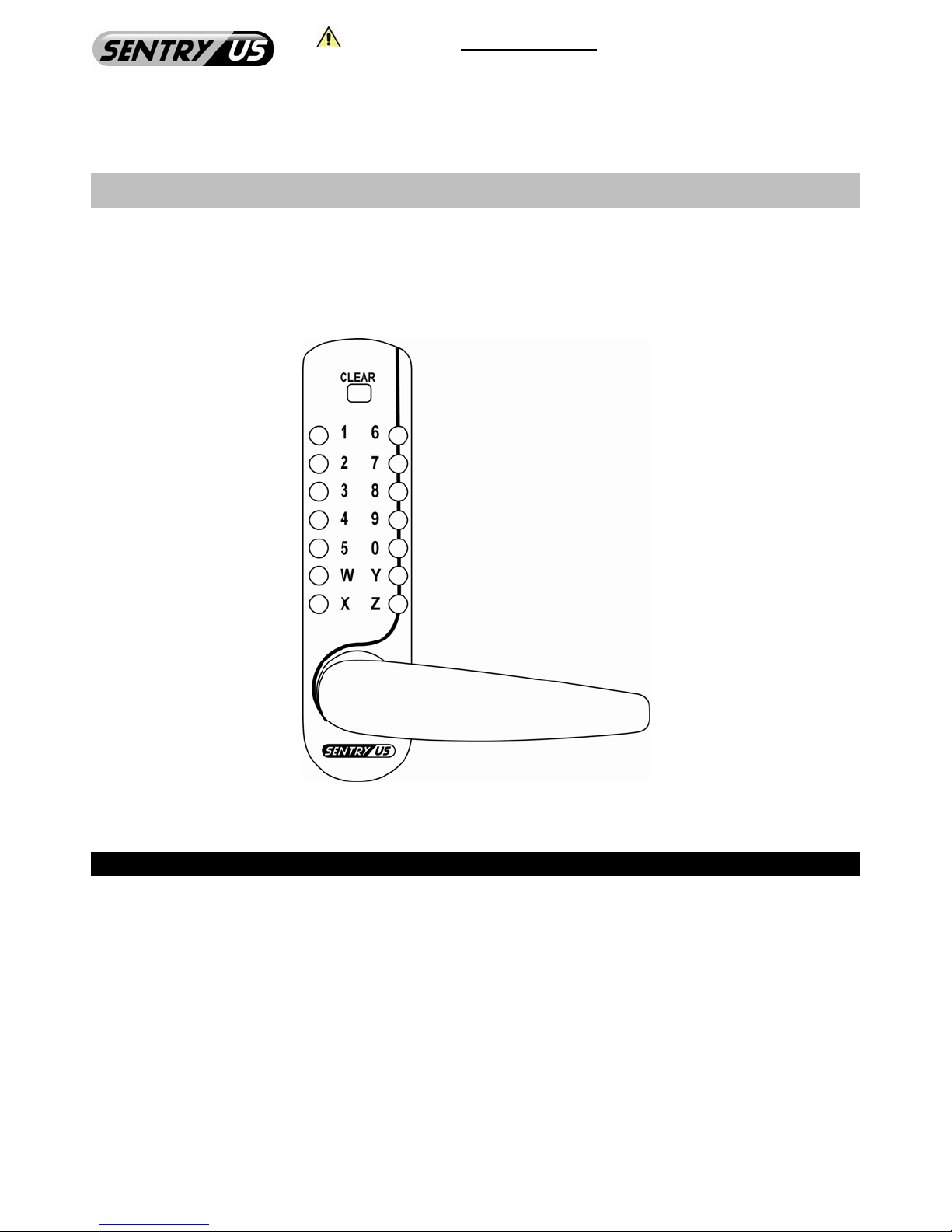
Please read the Operational Manual before attempting to use this product.
Installation manual subject to change without prior notice from the manufacturer.
Locks, cards, sensor and power adaptor not included.
Installation Manual
Mechanical Keyless Push Button Door Lock
SD-771-60S
SD-771-70H
Features
• Passage Function – Always unlocked
• Hold Back Function – Always Unlocked w/ Non-Latching
*Door Closer Recommended
*Inside Handle is down
• Disable Code Function – Night Latch
*Inside Handle is up
• Easy Code Combination Changing w/ over 16,000 Codes
• Suitable for Inside: Right Hand & Left Hand
Outside: Right Hand & Left Hand
• Color: Satin Chrome Finish 626 / US Code 26D
• No Software Required; Audit Free
• Keyless Entry Lock; No Batteries Required
2 3/8” / 60mm Backset
2 3/4” / 70mm Backset
Copyright © 2010. All rights reserved. 1 REV122010-V28
www.SentryUS.com
Page 2
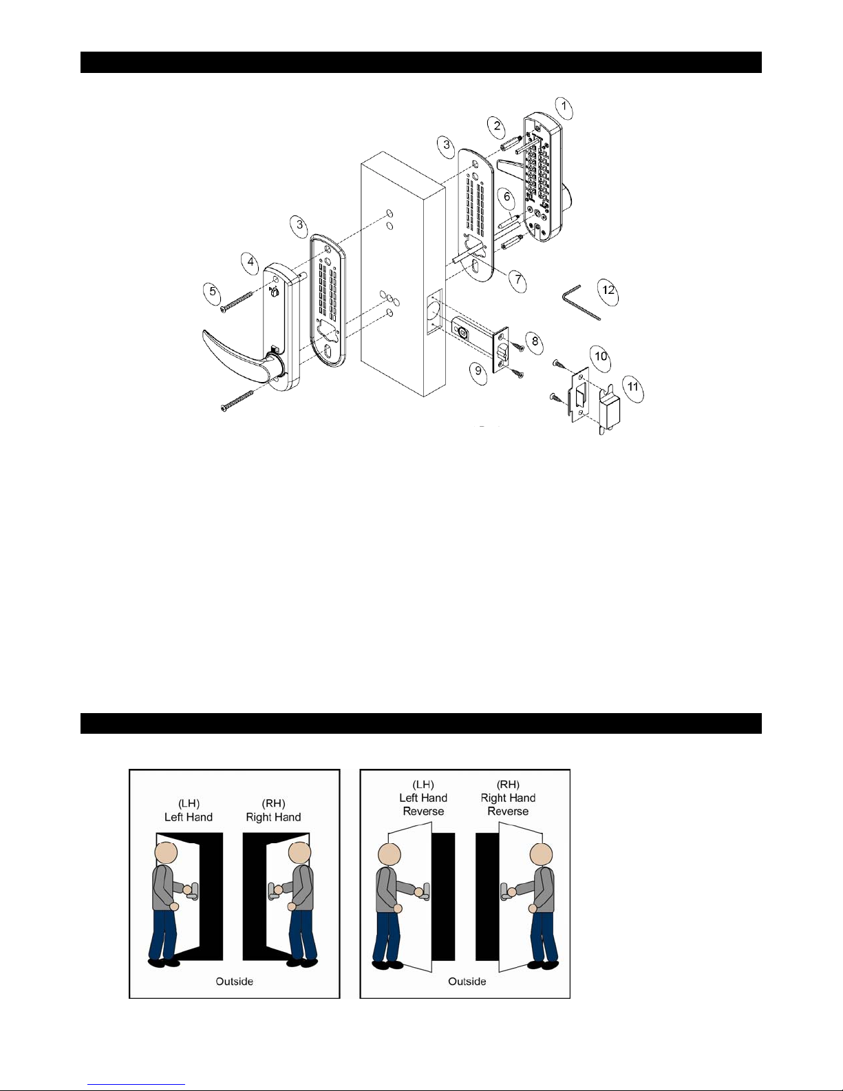
Parts
1. Mechanical Exterior Code Pad Assembly
2. Hex Lug, 1” / 25mm, x2
3. Neoprene Seals, x2
4. Mechanical Interior Code Pad Assembly
5. Fixing Interior Code Pad
2 Supplied 1.4” / 36mm (2 Spare 2” / 51mm)
6. Latch Bolt Support Post
NOTE:
Before commencing installation, check that all parts are working correctly.
• Mechanical Exterior and Interior Code Pad Assembly: Enter Factory default code C13579, turn handle in both
directions. The handle should turn and return freely under spring pressure.
• Mechanical Deadlatch Assembly: Check that the spring latch and spindle hub moves freely.
• If you need to change the code, you should change and test before installation.
Instructions
1) Check the hand of your door.
7. Spindle x3 (3” / 76mm, 3 .3” / 85mm, 3.9” / 100mm -- Only
one is used)
8. Wood Screws, x4 (used with Latch Bolt & Strike Plate)
9. Latch Bolt (2 3/8” / 60m m standard)
10. Strike Plate
11. Strike Box
12. Hex Wrench
When viewed from the outside, your door is right handed if the hinges are on the right.
Copyright © 2010. All rights reserved. 2 REV122010-V28
www.SentryUS.com
Page 3
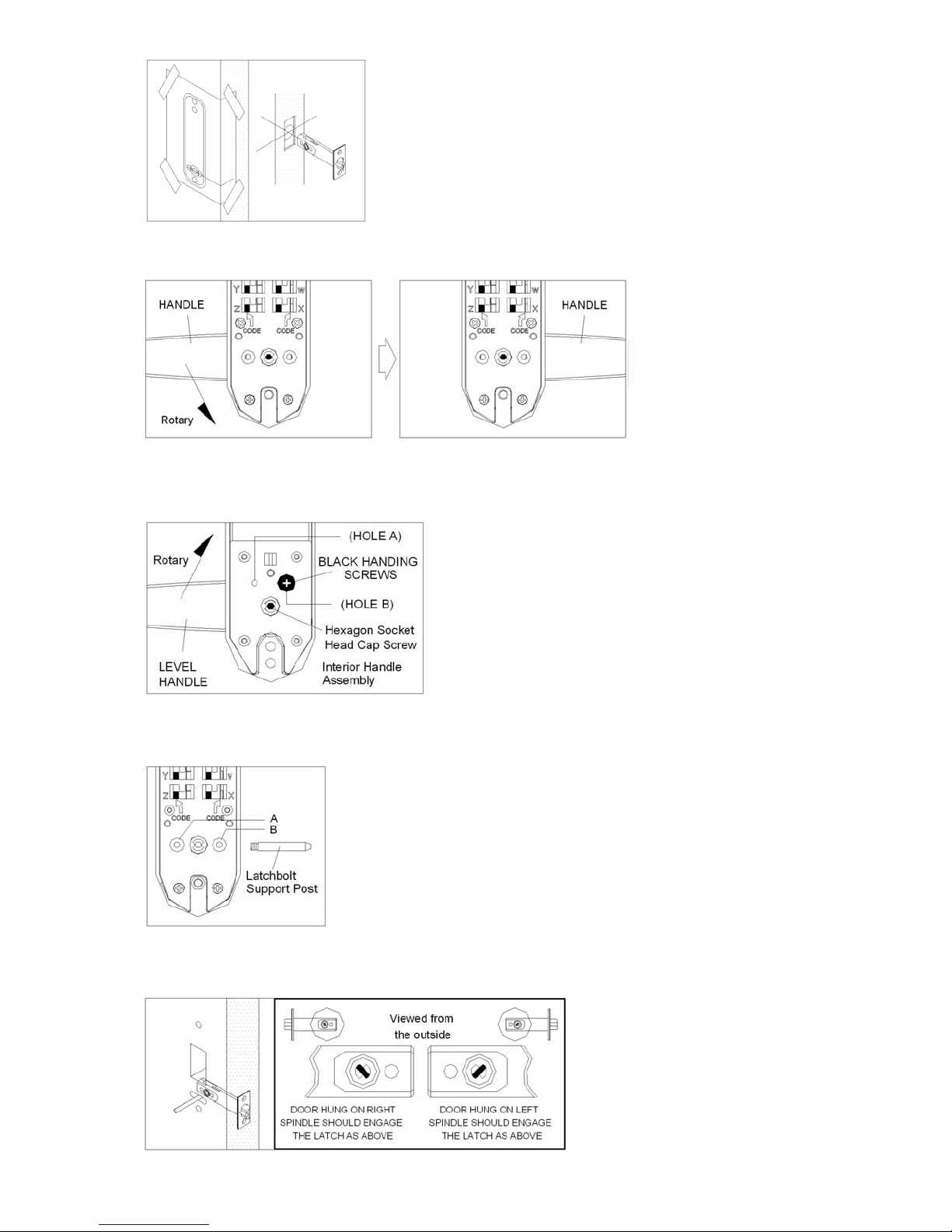
2) Apply the Template
3) Handling the Mechanical E xte r i o r Co de P ad As se m bly
4) Handling the Mechanical Interior Handle Assembly
5) Fit Latch Support Post
6) Positioning the Spindles
Copyright © 2010. All rights reserved. 3 REV122010-V28
www.SentryUS.com
Select the desired position on the door. Fold the template on the dotted 2
3/8” / 60mm backset line to suit the deadlatch assembly supplied. Tape
the template to the door. Mark and drill six (6) 0.4” / 10mm holes as
shown on the template. Mark the central point on the "center line of latch"
on the edge of the door and drill a 1” / 25mm hole to a depth of
3.3” / 85mm. Insert the latch into the latch holes and mark around the
face plate. Remove the latch and cut a 0.1” / 3mm rebate so that the face
plate fits flush with the edge of the door. Fit the latch assembly with 2
wood screws. (Ensure that the beveled face of the latch bolt faces the
door frame).
Apply strength to rotate the
handle to the desired direction.
Hole A is for left-handed doors and Hole B is for right-handed
doors. To change for a left-handed door:
Remove BLACK handling screw from Hole A and relocate it in
Hole B.
To change for a left hand:
Loosen the Hexagon Socket Head Cap Screw and rotate the
lever handle from right to left. Tighten the Hexagon Socket Head
Cap Screw and make sure the lever handle is horizontal. Enter
code and turn lever handle anti-clockwise. The lever handle
should turn and return freely.
Fit the Latch S upport Post in the back of the Mechanical Code Pad Assembly.
Hole A is for the left-handed door and Hole B is for the right-handed door.
Three (3) spi ndles are provided. Select the
spindle length to suit the door thickness.
For door thicknesses less than 1.4” /
35mm, use the shorter spindle (75mm).
For door thicknesses of 1.4” ~ 1.9” / 35 ~
50mm use the longer spindle (3.3” / 85mm
or 3.9” / 100mm). Position spindle centrally
through the latch hub to suit door handling.
Page 4
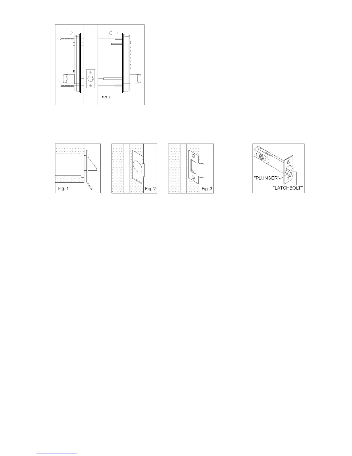
7) Mounting the Lock
8) Fitting the Strike Plate
Select the fixing screws to suit the door thickness. For door
thicknesses less than 1.9” / 48mm use the shorter screws (1.4” /
36mm). Fit the neoprene seals to both the Exterior Code Pad and
Interior Handle Assemblies. Hold the Exterior Code Pad Assembly
onto the door with the spindle in position and ensure that the latch
support post engages the hole in the deadlatch assembly. Locate the
Interior Handle Assembly on the inside of the door engaging the
spindle in the handle hub. Screw both sides together using the fitting
bolts top and bottom. (FIG 1). Before tightening the fixing screws,
make sure the lock is vertical. Test the mechanism to ensure that the
lock functions correctly and moves easily. DO NOT over tighten the
fixing screws; this may cause distortion and lead to poor operation.
CHECK THAT ALL THE CODE WORKS TO AVOID A LOCKOUT
BEFORE CLOSING THE DOOR.
Close the door against the door frame and transfer the center of the latch bolt onto the jamb. Position the strike
plate on the door so that it fits against the flat of the latch bolt, with deadlatch plunger depressed (Fig. 1). Close the
door and mark the position of the strike plate on the door jamb. Using the strike plate as a template, align it with the
position marks in the jamb and mark the inner and outer edges of the strike plate on the jamb. (Fig 2). Cut a 1mm
deep rebate so that the strike plate fits flush with door jamb (Fig 2). Drill and chisel out the latch bolt hole to
accommodate the latch bolt strike box (Fig 3). Fit strike plate and strike box using only one wood screw first to
ensure that it is positioned accurately. The latch bolt and the deadlatch plunger should enter the aperture freely and
be held without excessive play. When correctly positioned, secure with the second wood screw and check lock set
for smooth operation.
Copyright © 2010. All rights reserved. 4 REV122010-V28
www.SentryUS.com
 Loading...