

Page 1

Network Video Recorder
User Manual
Page 2

User Manual of Network Video Recorder
1
About this Manual
This Manual is applicable to Network Video Recorder (NVR).
The Manual includes instructions for using and managing the product. Pictures, charts, images and all other
information hereinafter are for description and explanation only. The information contained in the Manual is
subject to change, without notice, due to firmware updates or other reasons. Please find the latest version in the
company website
Please use this user manual under the guidance of professionals.
Legal Disclaimer
REGARDING TO THE PRODUCT WITH INTERNET ACCESS, THE USE OF PRODUCT SHALL BE WHOLLY AT YOUR OWN
RISKS. OUR COMPANY SHALL NOT TAKE ANY RESPONSIBILITES FOR ABNORMAL OPERATION, PRIVACY LEAKAGE
OR OTHER DAMAGES RESULTING FROM CYBER ATTACK, HACKER ATTACK, VIRUS INSPECTION, OR OTHER
INTERNET SECURITY RISKS; HOWEVER, OUR COMPANY WILL PROVIDE TIMELY TECHNICAL SUPPORT IF REQUIRED.
SURVEILLANCE LAWS VARY BY JURISDICTION. PLEASE CHECK ALL RELEVANT LAWS IN YOUR JU RISDICTION
BEFORE USING THIS PRODUCT IN ORDER TO ENSURE THAT YOUR USE CONFORMS THE APPLICABLE LAW. OUR
COMPANY SHALL NOT BE LIABLE IN THE EVENT THAT THIS PRODUCT IS USED WITH ILLEGITIMATE PURPOSES.
IN THE EVENT OF ANY CONFLICTS BETWEEN THIS MANUAL AND THE APPLICABLE LAW, THE LATER PREVAILS.
Page 3

User Manual of Network Video Recorder
2
Regulatory Information
FCC Information
FCC compliance: This equipment has been tested and found to comply with the limits for a digital device,
pursuant to part 15 of the FCC Rules. These limits are designed to provide reasonable protection against harmful
interference when the equipment is operated in a commercial environment. This equipment generates, uses, and
can radiate radio frequency energy and, if not installed and used in accordance with the instruction manual, may
cause harmful interference to radio communications. Operation of this equipment in a residential area is likely to
cause harmful interference in which case the user will be required to correct the interference at his own expense.
FCC Conditions
This device complies with part 15 of the FCC Rules. Operation is subject to the following two conditions:
1. This device may not cause harmful interference.
2. This device must accept any interference received, including interference that may cause undesired operation.
EU Conformity Statement
This product and - if applicable - the supplied accessories too are marked with "CE" and comply
therefore with the applicable harmonized European standards listed under the EMC Directive
2004/108/EC, the RoHS Directive 2011/65/EU.
2012/19/EU (WEEE directive): Products marked with this symbol cannot be disposed of as unsorted
municipal waste in the European Union. For proper recycling, return this product to your local
supplier upon the purchase of equivalent new equipment, or dispose of it at designated collection
points. For more information see: www.recyclethis.info
2006/66/EC (battery directive): This product contains a battery that cannot be disposed of as
unsorted municipal waste in the European Union. See the product documentation for specific
battery information. The battery is marked with this symbol, which may include lettering to indicate
cadmium (Cd), lead (Pb), or mercury (Hg). For proper recycling, return the battery to your supplier or to a
designated collection point. For more information see: www.recyclethis.info
Industry Canada ICES-003 Compliance
This device meets the CAN ICES-3 (B)/NMB-3(B) standards requirements.
Page 4
User Manual of Network Video Recorder
3
Safety Instruction
These instructions are intended to ensure that user can use the product correctly to avoid danger or property
loss.
The precaution measure is divided into “Warnings” and “Cautions”
Warnings: Serious injury or death may occur if any of the warnings are neglected.
Cautions: Injury or equipment damage may occur if any of the cautions are neglected.
Warnings
● Proper configuration of all passwords and other security settings is the responsibility of the installer and/or
end-user.
● In the use of the product, you must be in strict compliance with the electrical safety regulations of the nation
and region. Please refer to technical specifications for detailed information.
● Input voltage should meet both the SELV (Safety Extra Low Voltage) and the Limited Power Source with
100~240 VAC or 12 VDC according to the IEC60950-1 standard. Please refer to technical specifications for
detailed information.
● Do not connect several devices to one power adapter as adapter overload may cause over-heating or a fire
hazard.
● Please make sure that the plug is firmly connected to the power socket.
● If smoke, odor or noise rise from the device, turn off the power at once and unplug the power cable, and then
please contact the service center.
Warnings Follow these
safeguards to prevent serious
injury or death.
Cautions Follow these
precautions to prevent
potential injury or material
damage.
Page 5

User Manual of Network Video Recorder
4
Preventive and Cautionary Tips
Before connecting and operating your device, please be advised of the following tips:
• Ensure unit is installed in a well-ventilated, dust-free environment.
• Unit is designed for indoor use only.
• Keep all liquids away from the device.
• Ensure environmental conditions meet factory specifications.
• Ensure unit is properly secured to a rack or shelf. Major shocks or jolts to the unit as a result of dropping it
may cause damage to the sensitive electronics within the unit.
• Use the device in conjunction with an UPS if possible.
• Power down the unit before connecting and disconnecting accessories and peripherals.
• A factory recommended HDD should be used for this device.
• Improper use or replacement of the battery may result in hazard of explosion. Replace with the same or
equivalent type only. Dispose of used batteries according to the instructions provided by the manufacturer.
Page 6

User Manual of Network Video Recorder
5
Thank you for purchasing our product. If there is any question or request, please do not hesitate to contact dealer.
The figures in the manual are for reference only.
Page 7

User Manual of Network Video Recorder
6
Product Key Features
General
Connectable to network cameras, network dome and encoders.
Connectable to the third-party network cameras like ACTI, Arecont, AXIS, Bosch, Brickcom, Canon,
PANASONIC, Pelco, SAMSUNG, SANYO, SONY, Vivotek and ZAVIO, and cameras that adopt ONVIF or PSIA
protocol.
Connectable to the smart IP cameras.
PAL/NTSC adaptive video inputs.
Each channel supports dual-stream.
Up to 16 network cameras can be connected.
Independent configuration for each channel, including resolution, frame rate, bit rate, image quality, etc.
The quality of the input and output record is configurable.
Local Monitoring
Simultaneous HDMI
TM
and VGA outputs.
HDMI
TM
and VGA outputs at up to 1920×1080 resolution.
Multiple screen display in live view is supported, and the display sequence of channels is adjustable.
Live view screen can be switched in group, and manual switch and automatic cycle live view are also
provided, and the interval of automatic cycle can be adjusted.
Quick setting menu is provided for live view.
Motion detection, video tampering, VCA (Video Content Analysis) alarm, video exception alert and video
loss alert functions.
Privacy mask.
HDD Management
For 8ch/16ch models, 2 SATA hard disks can be connected;
For 4ch models, 1 SATA hard disk can be connected;
Each disk with a maximum of 6TB storage capacity.
8 network disks (NAS /IP SAN disks) can be connected.
Support S.M.A.R.T. and bad sector detection.
HDD group management.
Support HDD standby function.
HDD property: redundancy, read-only, read/write (R/W).
HDD quota management; different capacity can be assigned to different channel.
Recording and Playback
Holiday recording schedule configuration.
Continuous and event video recording parameters.
Multiple recording types: manual, continuous, alarm, motion, motion | alarm, motion & alarm, and VCA.
8 recording time periods with separated recording types each day.
Pre-record and post-record for alarm, motion detection for recording, and pre-record time for schedule
and manual recording.
Searching record files by events (alarm input/motion detection/VCA).
Playback by sub-periods.
Tag adding for record files, searching and playing back by tags.
Locking and unlocking record files.
Page 8

User Manual of Network Video Recorder
7
Local redundant recording.
Provide new playback interface with easy and flexible operation.
Searching and playing back record files by camera No., recording type, start time, end time, etc.
Smart search for the selected area in the video.
Zooming in when playback.
Reverse playback of multi-channel.
Supports pause, play reverse, speed up, speed down, skip forward, and skip backward when playback, and
locating by dragging the mouse.
Up to 16-ch synchronous playback.
Backup
Export video data by USB or SATA device.
Export video clips when playback.
Management and maintenance of backup devices.
Alarm and Exception
Configurable arming time of alarm input/output.
Alarm for video loss, motion detection, VCA, video tampering, HDD full, HDD error, network disconnected,
IP confliction, illegal login, abnormal record, and PoE power overload (for the models support PoE
interfaces only), etc.
Alarm triggers full screen monitoring, audio alarm, notifying surveillance center, sending email and alarm
output.
Automatic restore when system is abnormal.
Support VCA detection alarm and VCA search.
Other Local Functions
Operable by front panel (depends on model), mouse, and remote control.
Three-level user management; admin user is allowed to create many operating accounts and define their
operating permission, which includes the limit to access any channel.
Operation, alarm, exceptions and log recording and searching.
Manually triggering and clearing alarms.
Import and export of device configuration information.
Network Functions
1 self-adaptive 10M/100M/1000M network interfaces are provided.
Up to 16 independent PoE network interfaces are provided for POE series.
IPv6 is supported.
TCP/IP protocol, PPPoE, DHCP, DNS, DDNS, NTP, SADP, SMTP, SNMP, NFS, and iSCSI are supported.
TCP, UDP and RTP for unicast.
Auto/Manual port mapping by UPnP
TM
.
Extranet access by SimpleDDNS.
Support access by Cloud P2P.
Remote reverse playback via RTSP.
Support accessing by the platform via ONVIF.
Remote search, playback, download, locking and unlocking of the record files, and the breakpoint resume
is supported for downloading files.
Remote parameters setup; remote import/export of device parameters.
Remote viewing of the device status, system logs and alarm status.
Remote keyboard operation.
Page 9

User Manual of Network Video Recorder
8
Remote locking and unlocking of control panel and mouse.
Remote HDD formatting and program upgrading.
Remote system restart and shutdown.
Alarm and exception information can be sent to the remote host
Remotely start/stop recording.
Remotely start/stop alarm output.
Remote JPEG capture.
Two-way audio and voice broadcasting.
Embedded WEB server.
Page 10

User Manual of Network Video Recorder
9
TABLE OF CONTENTS
Product Key Features ................................................................................................................................. 6
Chapter 1 Introduction ................................................................................................................... 12
1.1 Front Panel .................................................................................................................................... 13
1.2 IR Remote Control Operations ....................................................................................................... 17
1.3 USB Mouse Operation ................................................................................................................... 20
1.4 Input Method Description ............................................................................................................. 21
1.5 Rear Panel ...................................................................................................................................... 22
Real Panel without POE Interface .................................................................................................... 22
Real Panel with POE Interface .......................................................................................................... 22
Chapter 2 Getting Started ............................................................................................................... 24
2.1 Starting Up and Shutting Down the NVR ....................................................................................... 25
2.2 Setting Admin Password ................................................................................................................ 26
2.3 Using the Wizard for Basic Configuration ...................................................................................... 26
2.4 Login and Logout ........................................................................................................................... 30
2.4.1 User Login ......................................................................................................................... 30
2.4.2 User Logout ....................................................................................................................... 31
2.5 Adding and Connecting the IP Cameras ......................................................................................... 32
2.5.3 Activating the IP Camera ................................................................................................... 32
2.5.4 Adding the Online IP Cameras .......................................................................................... 33
2.5.5 Editing the Connected IP cameras and Configuring Customized Protocols ....................... 36
2.5.6 Editing IP Cameras Connected to the PoE Interfaces ........................................................ 38
Chapter 3 Live View ........................................................................................................................ 40
3.1 Introduction of Live View .............................................................................................................. 41
3.2 Operations in Live View Mode ...................................................................................................... 42
3.2.1 Using the Mouse in Live View ........................................................................................... 42
3.2.2 Quick Setting Toolbar in Live View Mode ......................................................................... 43
3.3 Adjusting Live View Settings .......................................................................................................... 44
3.4 Channel-zero Encoding .................................................................................................................. 46
Chapter 4 PTZ Controls ................................................................................................................... 47
4.1 Configuring PTZ Settings ................................................................................................................ 48
4.2 Setting PTZ Presets, Patrols & Patterns .......................................................................................... 49
4.2.1 Customizing Presets .......................................................................................................... 49
4.2.2 Calling Presets ................................................................................................................... 49
4.2.3 Customizing Patrols ........................................................................................................... 50
4.2.4 Calling Patrols ................................................................................................................... 51
4.2.5 Customizing Patterns ........................................................................................................ 52
4.2.6 Calling Patterns ................................................................................................................. 52
4.2.7 Customizing Linear Scan Limit ........................................................................................... 53
4.2.8 Calling Linear Scan ............................................................................................................ 54
4.2.9 One-touch Park ................................................................................................................. 54
4.3 PTZ Control Panel .......................................................................................................................... 55
Chapter 5 Recording Settings .......................................................................................................... 57
Page 11

User Manual of Network Video Recorder
10
5.1 Configuring Parameters ................................................................................................................. 58
5.2 Configuring Recording Schedule .................................................................................................... 60
5.3 Configuring Motion Detection Recording ...................................................................................... 62
5.4 Configuring Alarm Triggered Recording ......................................................................................... 63
5.5 Configuring VCA Event Recording .................................................................................................. 65
5.6 Manual Recording.......................................................................................................................... 66
5.7 Configuring Holiday Recording ...................................................................................................... 67
5.8 Files Protection .............................................................................................................................. 68
5.8.1 Locking the Recording Files ............................................................................................... 68
Chapter 6 Playback .........................................................................................................................71
6.1 Playing Back Record Files ............................................................................................................... 72
6.1.1 Instant Playback ................................................................................................................ 72
6.1.2 Playing Back by Normal Search ......................................................................................... 72
6.1.3 Playing Back by Event Search ............................................................................................ 75
6.1.4 Playing Back by Tag ........................................................................................................... 76
6.1.5 Playing back by Smart Playback ........................................................................................ 78
6.1.6 Playing Back by System Logs ............................................................................................. 80
6.1.7 Playing Back External File ................................................................................................. 81
6.1.8 Playing Back by Sub-periods ............................................................................................. 82
Chapter 7 Backup ........................................................................................................................... 83
7.1 Backing up Record Files ................................................................................................................. 84
7.1.1 Quick Export ..................................................................................................................... 84
7.1.2 Backing up by Normal Video Search ................................................................................. 85
7.1.3 Backing up by Event Search .............................................................................................. 87
7.1.4 Backing up Video Clips ...................................................................................................... 88
7.2 Managing Backup Devices ............................................................................................................. 89
Chapter 8 Alarm Settings ................................................................................................................ 90
8.1 Setting Motion Detection Alarm .................................................................................................... 91
8.2 Setting Sensor Alarms .................................................................................................................... 92
8.3 Detecting Video Loss Alarm........................................................................................................... 93
8.4 Detecting Video Tampering Alarm ................................................................................................ 95
8.5 Handling Exceptions Alarm ............................................................................................................ 96
8.6 Setting Alarm Response Actions .................................................................................................... 97
8.7 Triggering or Clearing Alarm Output Manually .............................................................................. 99
Chapter 9 VCA Alarm .................................................................................................................... 101
9.1 Line Crossing Detection ............................................................................................................... 102
9.2 Intrusion Detection ...................................................................................................................... 103
Chapter 10 Network Settings .......................................................................................................... 105
10.1 Configuring General Settings ....................................................................................................... 106
10.2 Configuring Advanced Settings .................................................................................................... 106
10.2.1 PPPoE Settings ................................................................................................................ 106
10.2.2 Configuring Cloud P2P .................................................................................................... 107
10.2.3 Configuring DDNS ........................................................................................................... 108
10.2.4 Configuring NTP Server ................................................................................................... 109
Page 12

User Manual of Network Video Recorder
11
10.2.5 Configuring Remote Alarm Host ..................................................................................... 110
10.2.6 Configuring Multicast ...................................................................................................... 110
10.2.7 Configuring RTSP ............................................................................................................. 111
10.2.8 Configuring Server and HTTP Ports ................................................................................. 111
10.2.9 Configuring Email ............................................................................................................ 112
10.2.10 Configuring NAT .............................................................................................................. 113
10.3 Checking Network Traffic ............................................................................................................. 116
10.4 Configuring Network Detection ................................................................................................... 117
10.4.1 Testing Network Delay and Packet Loss .......................................................................... 117
10.4.2 Exporting Network Packet............................................................................................... 118
10.4.3 Checking the Network Status .......................................................................................... 119
10.4.4 Checking Network Statistics ............................................................................................ 120
Chapter 11 HDD Management ........................................................................................................ 121
11.1 Initializing HDDs ........................................................................................................................... 122
11.2 Managing Network HDD .............................................................................................................. 123
11.3 Configuring Quota Mode ............................................................................................................. 125
11.4 Checking HDD Status ................................................................................................................... 126
11.5 HDD Detection ............................................................................................................................. 127
11.6 Configuring HDD Error Alarms ..................................................................................................... 128
Chapter 12 Camera Settings ............................................................................................................ 129
12.1 Configuring OSD Settings ............................................................................................................. 130
12.2 Configuring Privacy Mask ............................................................................................................ 130
12.3 Configuring Video Parameters ..................................................................................................... 131
Chapter 13 NVR Management and Maintenance ............................................................................ 133
13.1 Viewing System Information ....................................................................................................... 134
13.2 Searching & Export Log Files ....................................................................................................... 134
13.3 Importing/Exporting IP Camera Info............................................................................................ 136
13.4 Importing/Exporting Configuration Files ..................................................................................... 136
13.5 Upgrading System ........................................................................................................................ 137
13.5.1 Upgrading by Local Backup Device .................................................................................. 137
13.5.2 Upgrading by FTP ............................................................................................................ 138
13.6 Restoring Default Settings ........................................................................................................... 139
Chapter 14 Others .......................................................................................................................... 140
14.1 Configuring General Settings ....................................................................................................... 141
14.2 Configuring DST Settings ............................................................................................................. 141
14.3 Configuring More Settings for Device Parameters ....................................................................... 142
14.4 Managing User Accounts ............................................................................................................. 142
14.4.1 Adding a User .................................................................................................................. 143
14.4.2 Deleting a User ................................................................................................................ 145
14.4.3 Editing a User .................................................................................................................. 145
14.5 Appendix ..................................................................................................................................... 147
Glossary.................................................................................................................................................. 147
Troubleshooting ..................................................................................................................................... 148
List of Compatible IP Cameras ................................................................................................................ 154
Page 13

User Manual of Network Video Recorder
12
Chapter 1 Introduction
Page 14
User Manual of Network Video Recorder
13
1.1 Front Panel
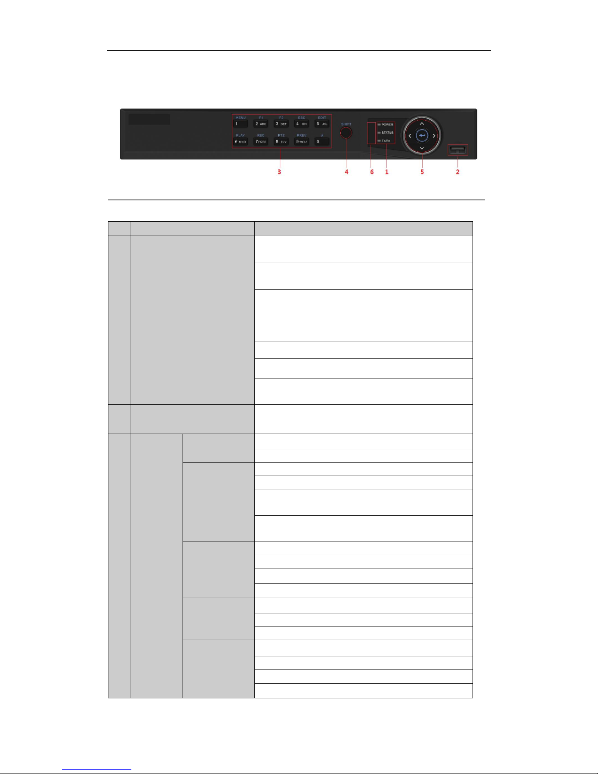
Figure 1. 1 Front Panel of 4CH/8CH NVR
Table 1. 1 Description of Control Panel Buttons
No.
Name
Function Description
1
Status Indicators
POWER: the POWER indicator turns green when NVR is
powered up.
READY: The indicator light is green when the device is running
normally.
STATUS: 1.The light is green when the IR remote control is
enabled; 2.The light is red when the function of the
composite keys (SHIFT) are used; 3. The light is out when
none of the above condition is met/
ALARM: the light is red when there is an alarm occurring.
HDD: the indicator flickers red when HDD is reading/writing.
Tx/Rx: TX/RX indicator flickers green when network
connection is functioning normally.
2
USB Interfaces
Universal Serial Bus (USB) ports for additional devices such as
USB mouse and USB Hard Disk Drive (HDD).
3
Composite
Keys
1/MENU:
Enter numeral “1”;
Access the main menu interface.
2/ABC/F1:
Enter numeral “2”;
Enter letters “ABC”;
The F1 button when used in a list field will select all items in
the list.
In PTZ Control mode, it will turn on/off PTZ light and when
the image is zoomed in, the key is used to zoom out.
3/DEF/F2:
Enter numeral “3”;
Enter letters “DEF”;
The F2 button is used to change the tab pages.
In PTZ control mode, it zooms in the image.
4/GHI/ESC:
Enter numeral “4”;
Enter letters “GHI”;
Exit and back to the previous menu.
5/JKL/EDIT:
Enter numeral “5”;
Enter letters “JKL”;
Delete characters before cursor;
Check the checkbox and select the ON/OFF switch;
Page 15
User Manual of Network Video Recorder
14
No.
Name
Function Description
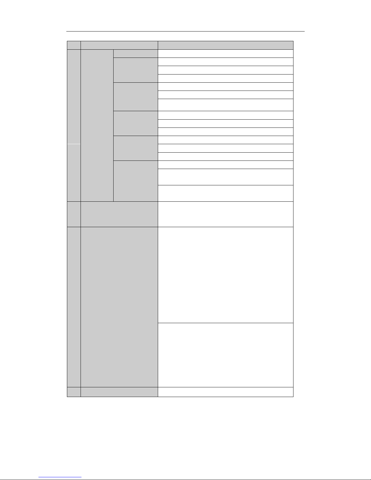
Start/stop record clipping in playback.
6/MNO/PLAY:
Enter numeral “6”;
Enter letters “MNO”;
Playback, for direct access to playback interface.
7/PQRS/REC:
Enter numeral “7”;
Enter letters “PQRS”;
Open the manual record interface.
8/TUV/PTZ:
Enter numeral “8”;
Enter letters “TUV”;
Access PTZ control interface.
9/WXYZ/PREV:
Enter numeral “9”;
Enter letters “WXYZ”;
Multi-channel display in live view.
0/A:
Enter numeral “0”;
Shift the input methods in the editing text field. (Upper and
lowercase, alphabet, symbols or numeric input).
Double press the button to switch the main and auxiliary
output.
4
SHIFT
Switch between the numeric or letter input and functions of
the composite keys. (Input letter or numbers when the light is
out; Realize functions when the light is red.)
5
Control Buttons
Directional buttons:
In menu mode, the direction buttons are used to navigate
between different fields and items and select setting
parameters.
In playback mode, the Up and Down buttons are used to
speed up and slow down record playing, and the Left and
Right buttons are used to move the recording 30s forwards or
backwards.
In the image setting interface, the up and down button can
adjust the level bar of the image parameters.
In live view mode, these buttons can be used to switch
channels.
Enter:
The Enter button is used to confirm selection in menu mode;
or used to check checkbox fields and ON/OFF switch.
In playback mode, it can be used to play or pause the video.
In single-frame play mode, pressing the Enter button will play
the video by a single frame.
And in auto sequence view mode, the buttons can be used to
pause or resume auto sequence.
6
IR Receiver
Receiver for IR remote.
Page 16
User Manual of Network Video Recorder
15
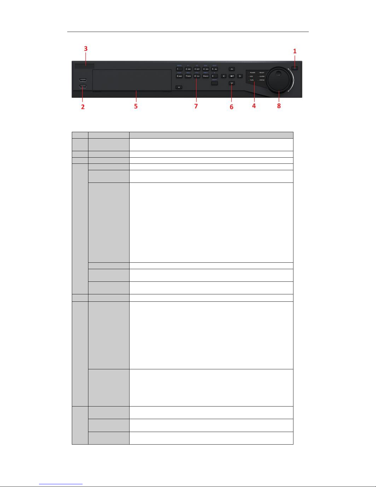
Figure 1.2 Front Panel of 16CH/32CH NVR
Table 1. 2 Description of Control Panel Buttons
No.
Name
Function Description
1
POWER
ON/OFF
Power on/off switch.
2
USB Interface
Connect to USB mouse or USB flash memory.
3
IR Receiver
Receiver for IR remote control. devices.
4
POWER
Power indicator lights in green when DVR is powered up.
READY
Ready indicator is normally green, indicating that the DVR is functioning
properly.
STATUS
Indicator turns green when DVR is controlled by an IR remote control with
the address from 1~254;
Indicator turns red when the SHIFT button is used;
Indicator does not light when the DVR is controlled by a keyboard or by
the IR remote control with the address of 255;
Indicator turns green when the DVR is controlled by IR remote control
(with the address from 1~254) and keyboard at the same time , and the
SHIFT button is not used;
Indicator turns orange : (a) when the DVR is controlled by IR remote
control (with the address from 1~254) and keyboard at the same time and
the SHIFT button is used as well; (b) when the DVR is controlled by IR
remote control (with the address from 1~254) and the SHIFT button is
used.
ALARM
Alarm indicator turns red when a sensor alarm is detected.
HDD
HDD indicator blinks in red when data is being read from or written to
HDD.
Tx/Rx
TX/RX indictor blinks in green when network connection is functioning
properly.
5
DVD-ROM
Slot for DVD-ROM.
6
DIRECTION
The DIRECTION buttons are used to navigate between different fields and
items in menus.
In Playback mode, the Up and Down button is used to speed up and slow
down recorded video.
In All-day Playback mode, the Left/Right button can be used to select the
recorded video of next/previous day; in Playback by Normal Video Search,
the Left/Right button can be used to select the next/previous recorded
file.
In Live View mode, the directional buttons can be used to cycle through
channels.
In PTZ control mode, it can control the movement of the PTZ camera.
ENTER
Confirm selection in any of the menu modes. It can also be used to tick
checkbox fields.
In Playback mode, it can be used to play or pause the video.
In Single-frame Playback mode, pressing the ENTER button will advance
the video by a single frame.
In Auto-switch mode, it can be used to stop /start auto switch.
7
SHIFT
Switch of compound keys between the numeric/letter input and
functional control.
1/MENU
Enter numeral “1”;
Access the main menu interface.
2ABC/F1
Enter numeral “2”;
Enter letters “ABC”;
Page 17

User Manual of Network Video Recorder
16
The F1 button can be used to select all items on the list;
In PTZ Control mode, the F1 button can be used to zoom out (zoom-) the
PTZ camera;
In live view or playback mode, the F1 button can be used to switch
between main and spot video output.
3DEF/F2
Enter numeral “3”;
Enter letters “DEF”;
In PTZ Control mode, the F1 button can be used to zoom in (zoom+) the
PTZ camera;
The F2 button can be used to cycle through tab pages.
4GHI/ESC
Enter numeral “4”;
Enter letters “GHI”;
Exit and back to the previous menu.
5JKL/EDIT
Enter numeral “5”;
Enter letters “JKL”;
Delete characters before cursor;
Select the checkbox and ON/OFF switch;
Start/stop record clipping in playback.
6MNO/PLAY
Enter numeral “6”;
Enter letters “MNO”;
In Playback mode, it is used for direct access to playback interface.
7PQRS/REC
Enter numeral “7”;
Enter letters “PQRS”;
Manual record, for direct access to manual record interface; manually
enable/disable record.
8TUV/PTZ
Enter numeral “8”;
Enter letters “TUV”;
Access PTZ control interface.
9WXYZ/PREV
Enter numeral “9”;
Enter letters “WXYZ”;
Multi-camera display in live view;
In Playback mode or MenuPlaybackTag playback interface, this button
can be used to delete the selected tag.
0/A
Enter numeral “0”;
Switch between input methods (upper and lowercase alphabet, symbols
and numeric input).
In Playback mode, this button can be used to add the default tag.
8
JOG SHUTTLE
Control
Move the active selection in a menu. The inner ring will move the
selection up and down; the outer ring will move it left and right.
In Playback mode, the inner ring is used to jump 30s forward/backward in
video files. The outer ring can be used to speed up/slow down the video.
In Live View mode, it can be used to cycle through different channels.
In PTZ control mode, in can control the movement of the PTZ camera.
Page 18
User Manual of Network Video Recorder
17
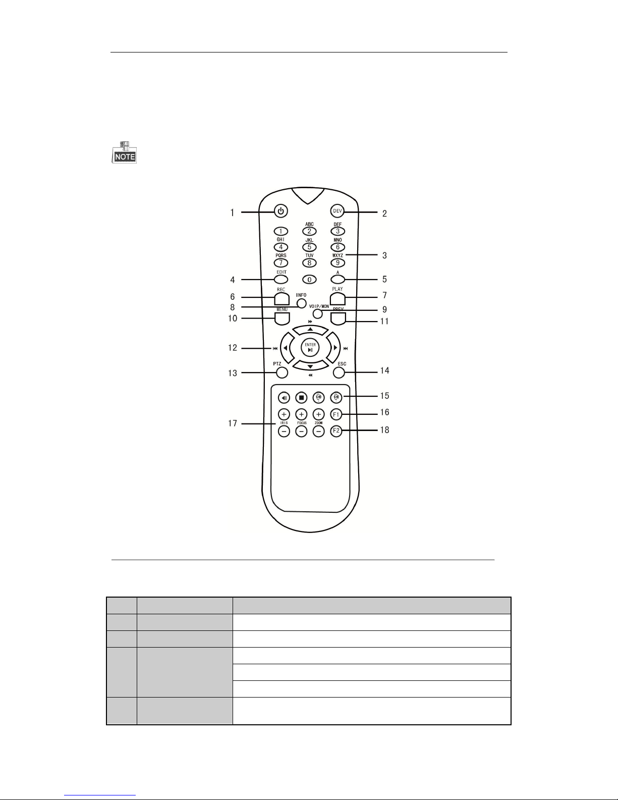
1.2 IR Remote Control Operations
The NVR may also be controlled with the included IR remote control, shown in Figure 1. 3.
Batteries (2×AAA) must be installed before operation.
Figure 1. 3 Remote Control
The keys on the remote control closely resemble the ones on the front panel.
Table 1. 3 Description of the Soft Keyboard Icons
No.
Name
Description
1
POWER
Power on/off the device.
2
DEV
Enables/Disables Remote Control.
3
Alphanumeric Buttons
Switch to the corresponding channel in Live view or PTZ Control mode.
Input numbers and characters in Edit mode.
Switch between different channels in the Playback mode.
4
EDIT Button
Edit text fields. When editing text fields, it will also function as a Backspace
button to delete the character in front of the cursor.
Page 19

User Manual of Network Video Recorder
18
No.
Name
Description
On checkbox fields, pressing the button will check the checkbox.
In PTZ Control mode, the button adjusts the iris of the camera.
In Playback mode, it can be used to generate video clips for backup.
Enter/exit the folder of USB device.
5
A Button
Adjust focus in the PTZ Control menu.
It is also used to switch between input methods (upper and lowercase
alphabet, symbols and numeric input).
6
REC Button
Enter the Manual Record setting menu.
In PTZ control settings, press the button and then you can call a PTZ preset by
pressing Numeric button.
It is also used to turn audio on/off in the Playback mode.
7
PLAY Button
The button is used to enter the All-day Playback mode.
It is also used to auto scan in the PTZ Control menu.
8
INFO Button
Reserved.
9
VOIP Button
Switch between main and spot output.
In PTZ Control mode, it can be used to zoom out the image.
10
MENU Button
Press the button will help you return to the Main menu (after successful
login).
Press and hold the button for 5 seconds will turn off audible key beep.
In PTZ Control mode, the MENU button will start wiper (if applicable).
In Playback mode, it is used to show/hide the control interface.
11
PREV Button
Switch between single screen and multi-screen mode.
In PTZ Control mode, it is used to adjust the focus in conjunction with the
A/FOCUS+ button.
12
DIRECTION Button
Navigate between different fields and items in menus.
In the Playback mode, the Up and Down button is used to speed up and slow
down recorded video. The Left and Right button will select the next and
previous record files.
In Live View mode, these buttons can be used to cycle through channels.
In PTZ control mode, it can control the movement of the PTZ camera.
ENTER Button
Confirm selection in any of the menu modes.
It can also be used to tick checkbox fields.
In Playback mode, it can be used to play or pause the video.
In single-frame Playback mode, pressing the button will advance the video by
a single frame.
13
PTZ Button
In Auto-switch mode, it can be used to stop /start auto switch.
14
ESC Button
Back to the previous menu.
Press for Arming/disarming the device in Live View mode.
15
RESERVED
Reserved for future usage.
16
F1 Button
Select all items on the list when used in a list field.
In PTZ Control mode, it will turn on/off PTZ light (if applicable).
Page 20

User Manual of Network Video Recorder
19
No.
Name
Description
In Playback mode, it is used to switch between play and reverse play.
17
PTZ Control Buttons
Buttons to adjust the iris, focus and zoom of a PTZ camera.
18
F2 Button
Cycle through tab pages.
In synchronous playback mode, it is used to switch between channels.
Troubleshooting Remote Control:
Make sure you have installed batteries properly in the remote control. And you have to aim the remote
control at the IR receiver in the front panel.
If there is no response after you press any button on the remote, follow the procedure below to troubleshoot.
Steps:
1. Go to Menu > Settings > General > More Settings by operating the front control panel or the mouse.
2. Check and remember NVR ID#. The default ID# is 255. This ID# is valid for all the IR remote controls.
3. Press the DEV button on the remote control.
4. Enter the NVR ID# you set in step 2.
5. Press the ENTER button on the remote.
If the Status indicator on the front panel turns blue, the remote control is operating properly. If the Status
indicator does not turn blue and there is still no response from the remote, please check the following:
1. Batteries are installed correctly and the polarities of the batteries are not reversed.
2. Batteries are fresh and not out of charge.
3. IR receiver is not obstructed.
If the remote still can’t function properly, please change a remote and try again, or contact the device provider.
Page 21

User Manual of Network Video Recorder
20
1.3 USB Mouse Operation
A regular 3-button (Left/Right/Scroll-wheel) USB mouse can also be used with this NVR. To use a USB mouse:
1. Plug USB mouse into one of the USB interfaces on the front panel of the NVR.
2. The mouse should automatically be detected. If in a rare case that the mouse is not detected, the possible
reason may be that the two devices are not compatible, please refer to the recommended the device list
from your provider.
The operation of the mouse:
Table 1. 4 Description of the Mouse Control
Name
Action
Description
Left-Click
Single-Click
Live view: Select channel and show the quick set menu.
Menu: Select and enter.
Double-Click
Live view: Switch between single-screen and multi-screen.
Click and Drag
PTZ control: pan, tilt and zoom.
Video tampering, privacy mask and motion detection: Select target
area.
Digital zoom-in: Drag and select target area.
Live view: Drag channel/time bar.
Right-Click
Single-Click
Live view: Show menu.
Menu: Exit current menu to upper level menu.
Scroll-Wheel
Scrolling up
Live view: Previous screen.
Menu: Previous item.
Scrolling down
Live view: Next screen.
Menu: Next item.
Page 22
User Manual of Network Video Recorder
21
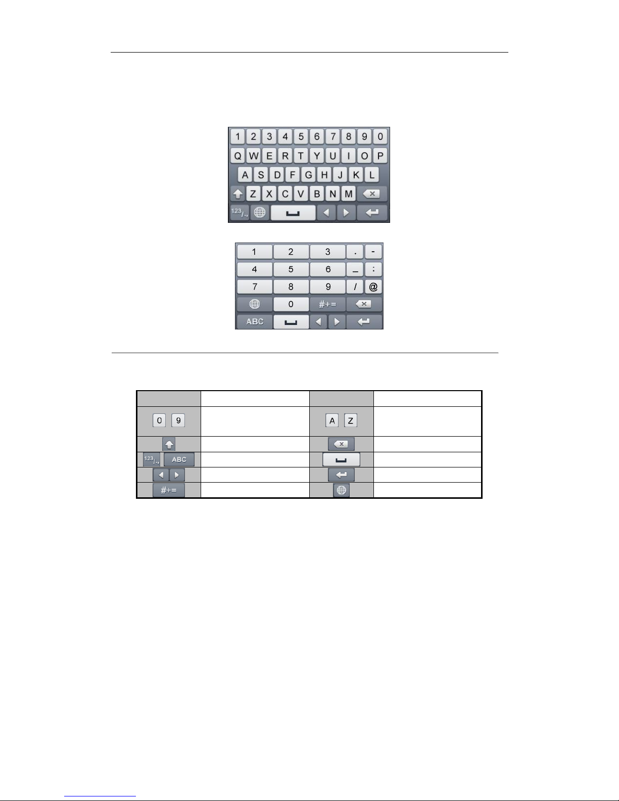
1.4 Input Method Description
Figure 1. 4 Soft Keyboard (1)
Figure 1. 5 Soft Keyboard (2)
Description of the buttons on the soft keyboard:
Table 1. 5 Description of the Soft Keyboard Icons
Icon
Description
Icon
Description
…
Number
…
English letter
Lowercase/Uppercase
Backspace
Switch the keyboard
Space
Positioning the cursor
Exit
Symbols
Reserved
Page 23
User Manual of Network Video Recorder
22
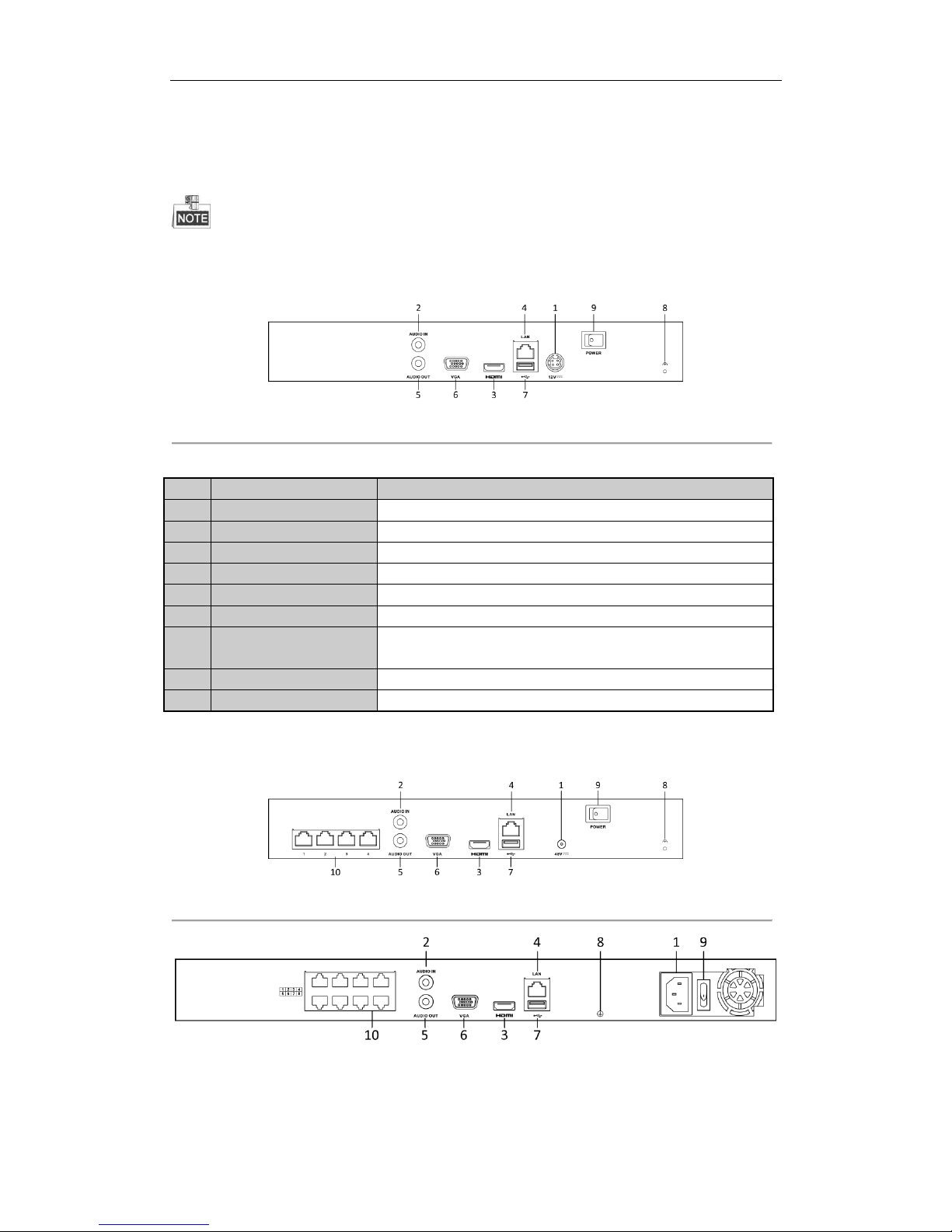
1.5 Rear Panel
The rear panel vaires according to different models.
Real Panel without POE Interface
Figure 1. 6 Real Panel without POE Interface
Table 1. 6 Description of Rear Panel Interfaces
No.
Item
Description
1
Power Supply
DC 12V power supply.
2
Audio In
RCA connector for audio input.
3
HDMITM Interface
HDMITM video output connector.
4
LAN Network Interface
10 /100 /1000 Mbps self-adaptive Ethernet interface
5
Audio Out
RCA connector for audio output.
6
VGA Interface
DB9 connector for VGA output. Display local video output and menu.
7
USB Interface
Universal Serial Bus (USB) ports for additional devices such as USB
mouse and USB Hard Disk Drive (HDD).
8
Ground
Ground (needs to be connected when NVR starts up).
9
Power Switch
Switch for turning on/off the device.
Real Panel with POE Interface
Figure 1. 7 Real Panel for 4-ch Device
Figure 1. 8 Real Panel for 8-ch Device
Page 24
User Manual of Network Video Recorder
23
The 16-ch devices have both 8 and 16 independent 100 Mbps PoE network interfaces models.
Table 1. 7 Description of Rear Panel Interfaces
No.
Item
Description
1
Power Supply
DC 48V power supply for 4-ch device and AC 100~240V for 8-ch and
16-ch devices.
2
Audio In
RCA connector for audio input.
3
HDMITM Interface
HDMITM video output connector.
4
LAN Network Interface
10 /100 /1000 Mbps self-adaptive Ethernet interface
5
Audio Out
RCA connector for audio output.
6
VGA Interface
DB9 connector for VGA output. Display local video output and menu.
7
USB Interface
Universal Serial Bus (USB) ports for additional devices such as USB
mouse and USB Hard Disk Drive (HDD).
8
Ground
Ground (needs to be connected when NVR starts up).
9
Power Switch
Switch for turning on/off the device.
10
Network Interfaces with
PoE function
Network interfaces for the cameras and to provide power over
Ethernet.
Page 25

User Manual of Network Video Recorder
24
Chapter 2 Getting Started
Page 26
User Manual of Network Video Recorder
25
2.1 Starting Up and Shutting Down the NVR
Purpose:
Proper startup and shutdown procedures are crucial to expanding the life of the NVR.
Before you start:
Check that the voltage of the extra power supply is the same with the NVR’s requirement, and the ground
connection is working properly.
Starting up the NVR:
Steps:
1. Check the power supply is plugged into an electrical outlet. It is HIGHLY recommended that an
Uninterruptible Power Supply (UPS) be used in conjunction with the device. The Power indicator LED on the
front panel should be red, indicating the device gets the power supply.
2. Turn on the power switch on the rear panel if the device starts up for the first time, or press the
button on the front panel if the model support front panel buttons. The Power indicator LED should turn
green indicating that the unit begins to start up.
Shutting down the NVR
Steps:
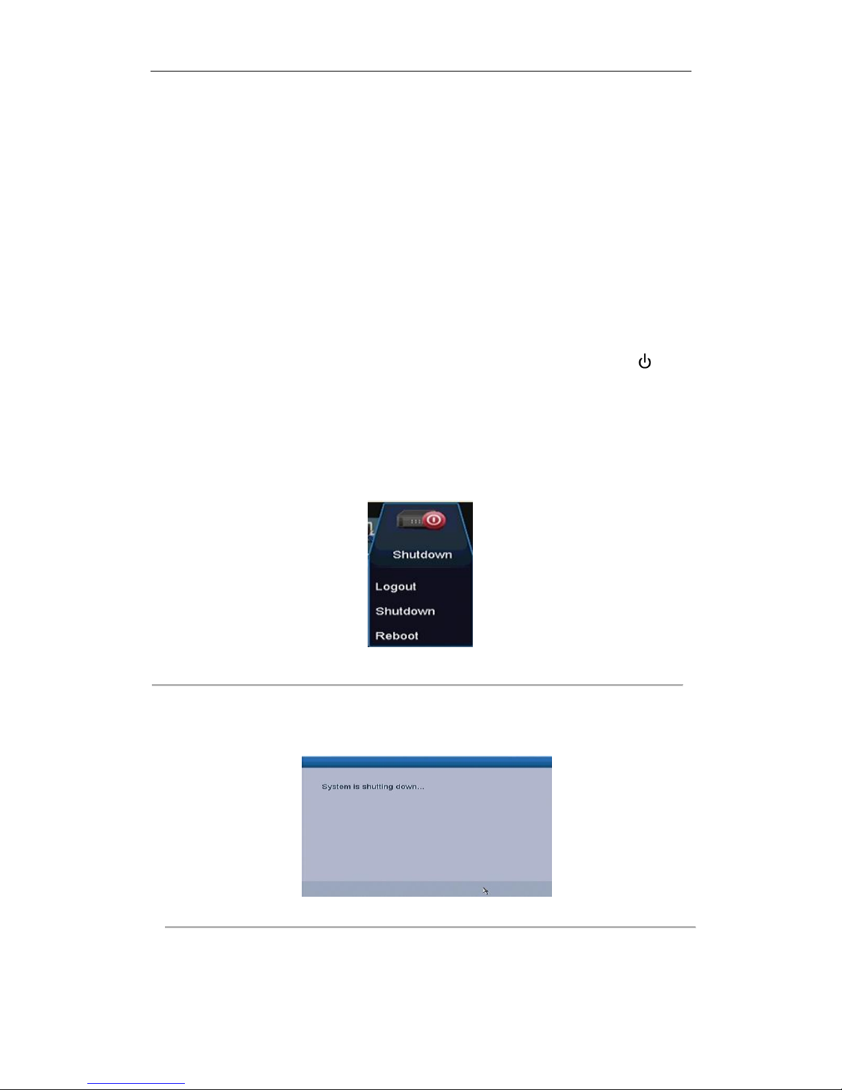
1. Enter the Shutdown menu.
Menu > Shutdown
Figure 2. 1 Shutdown Menu
2. Click the Shutdown button.
3. Click the Yes button.
4. Turn off the power switch on the rear panel when the attention pops up.
Figure 2. 2 Shutdown Attention
Rebooting the NVR
In the Shutdown menu, you can also reboot the NVR.
Page 27

User Manual of Network Video Recorder
26
Steps:
1. Enter the Shutdown menu by clicking Menu > Shutdown.
2. Click the Logout button to lock the NVR or the Reboot button to reboot the NVR.
2.2 Setting Admin Password
Purpose:
For the first-time access, you need to activate the device by setting an admin password. No operation is allowed
before activation.
Steps:
1. Input the same password in the text field of Create New Password and Confirm New Password.
Figure 2. 3 Settings Admin Password
STRONG PASSWORD RECOMMENDED– We highly recommend you create a strong password
of your own choosing (using a minimum of 8 characters, including upper case letters, lower
case letters, numbers, and special characters) in order to increase the security of your product.
And we recommend you reset your password regularly, especially in the high security system,
resetting the password monthly or weekly can better protect your product.
2. Click OK to save the password and activate the device.
2.3 Using the Wizard for Basic Configuration
Purpose:
After admin password is set, the setup wizard pops up automatically. It can walk you through some basic settings
of the NVR.
Page 28
User Manual of Network Video Recorder
27
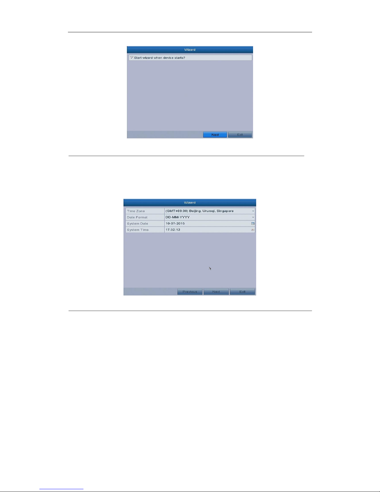
Figure 2. 4 Start Wizard Interface
Steps:
1. If you don’t want to use the setup wizard at that moment, click the Exit button. You can also choose to use
the Setup Wizard next time by leaving the “Start wizard when the device starts?” checkbox checked.
2. Click the Next button to enter the Date and Time Settings interface.
Figure 2. 5 Date and Time Settings
3. After the time settings, click Next button which takes you back to the Basic Network Setup Wizard
interface.
Page 29
User Manual of Network Video Recorder
28
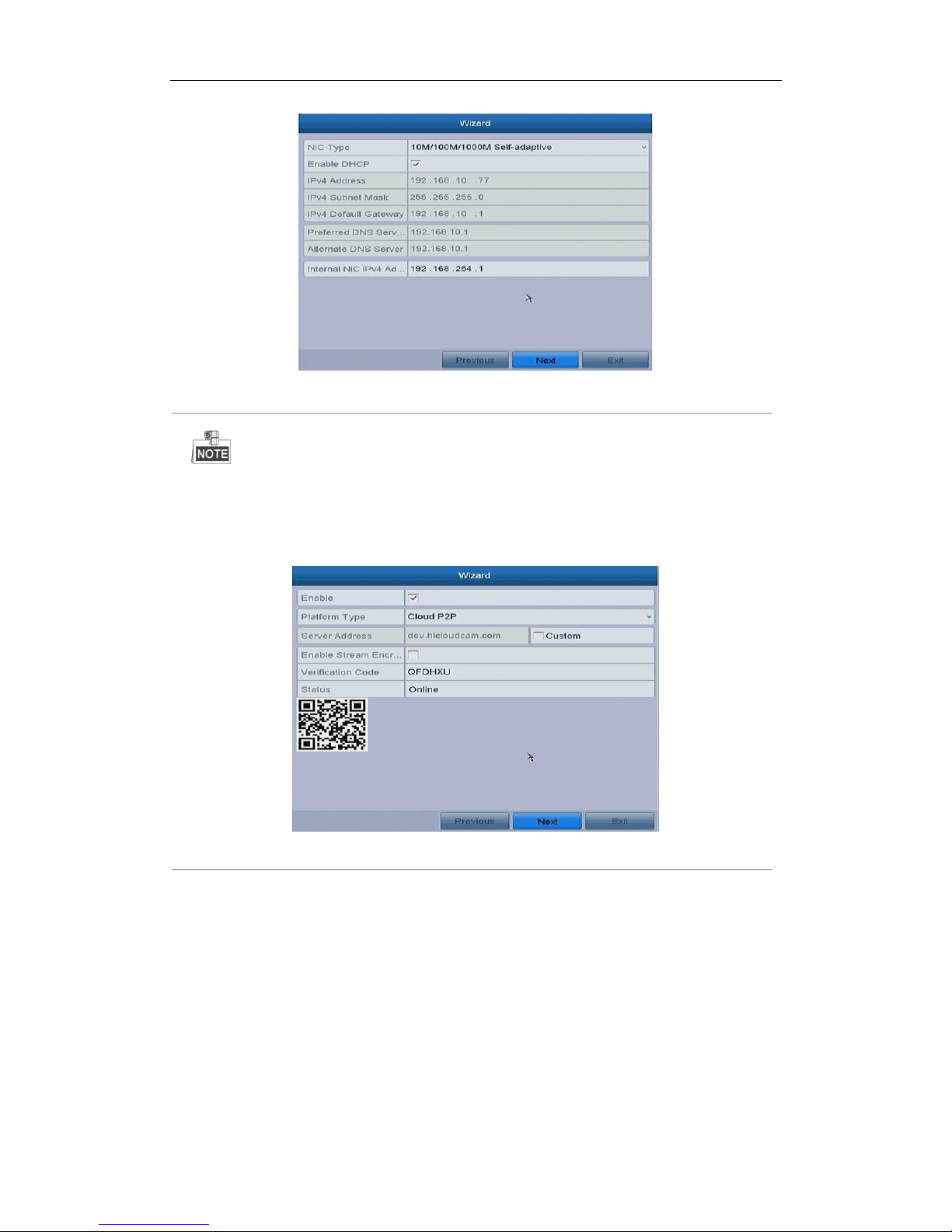
Figure 2. 6 Network Configuration for Models with POE Interface
For the models have the PoE the internal NIC IPv4 address should be configured for the cameras
connecting to the PoE or built-in switch network interface of the NVR.
4. Click Next button after you configured the basic network parameters. Then you will enter the Cloud P2P
interface. Configure the Cloud P2P according to your need.
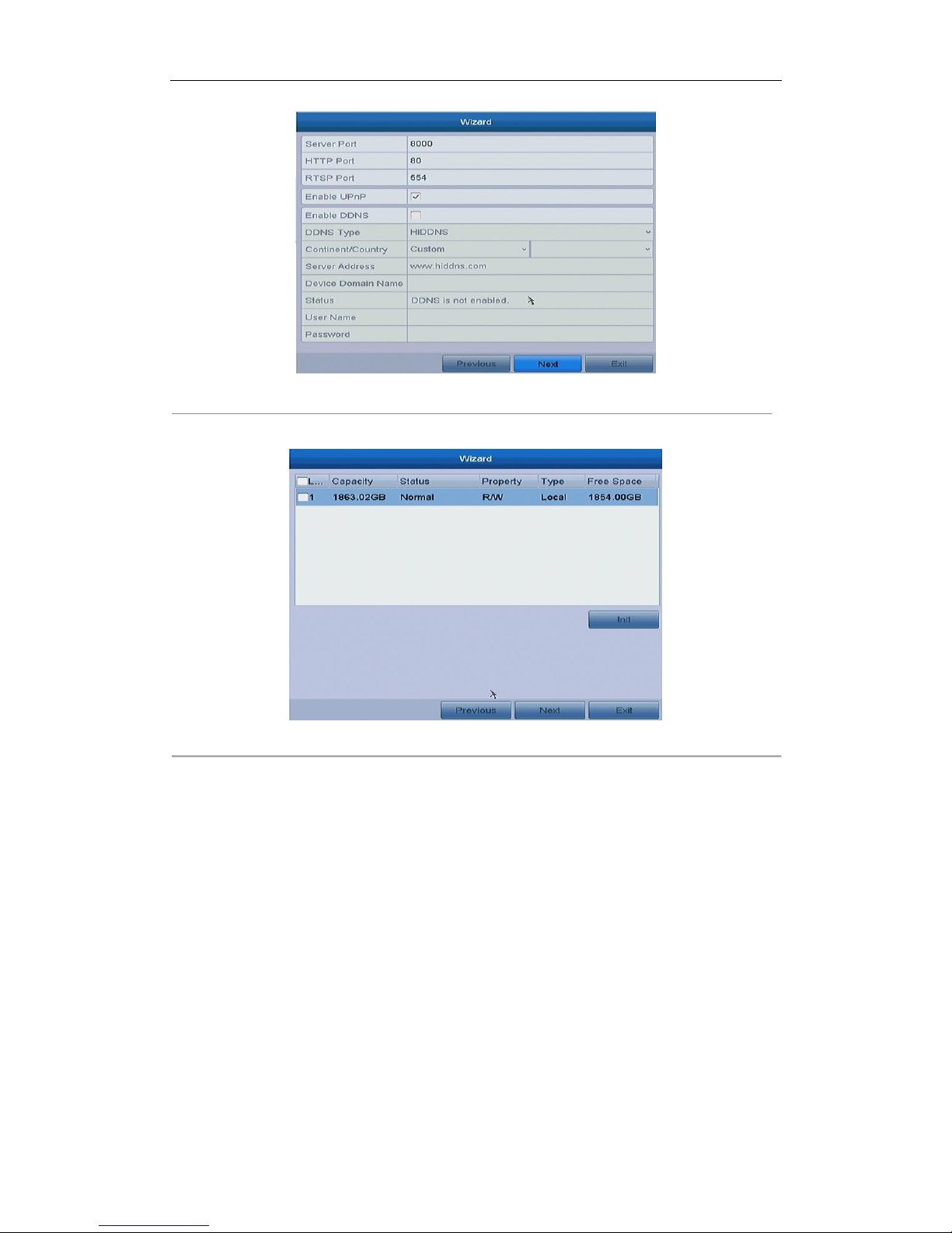
Figure 2. 7 Advanced Network Parameters
5. Click Next button to enter the Advanced Network Parameter interface. You can enable PPPoE, enable
DDNS and set other ports according to your need.
Page 30
User Manual of Network Video Recorder
29
Figure 2. 8 Advanced Network Parameters
6. After configuration finishes, click Next button to enter HDD Management interface.
Figure 2. 9 HDD Management
7. To initialize the HDD, click the Init button. Initialization removes all the data saved in the HDD.
8. Click Next button to enter the IP Camera Management interface.
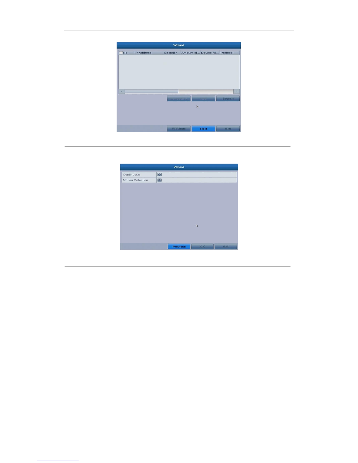
9. Click Search to search the online IP Camera and the Security status shows whether it is active or inactive.
Before adding the camera, make sure the IP camera to be added is in active status.
If the camera is in inactive status, you can click the inactive icon of the camera to set the password to
activate it. You can also select multiple cameras from the list and click the One-touch Activate to activate
the cameras in batch.
Click the Add to add the camera.
Page 31
User Manual of Network Video Recorder
30
Figure 2. 10 IP Camera Management
10. Click Next button. Configure the recording for the searched IP Cameras.
Figure 2. 11 Record Settings
11. Click OK to complete the startup Setup Wizard.
2.4 Login and Logout
2.4.1 User Login
Purpose:
If NVR has logged out, you must login the device before operating the menu and other functions.
Steps:
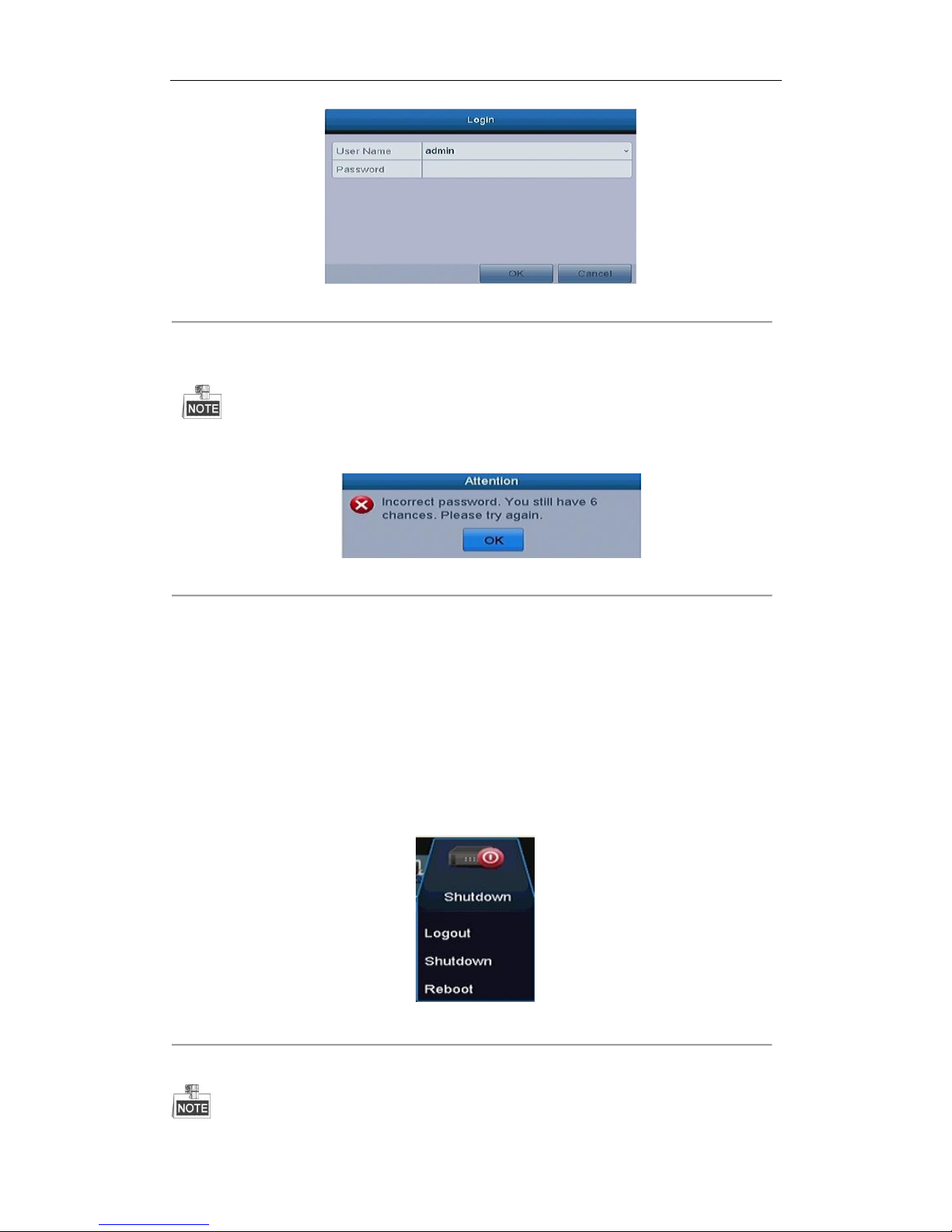
1. Select the User Name in the dropdown list.
Page 32
User Manual of Network Video Recorder
31
Figure 2. 12 Login Interface
2. Input Password.
3. Click OK to log in.
The device gets locked if the admin user performs 7 failed password attempts (5 attempts for the
guest/operator).
Figure 2. 13 User Account Protection
2.4.2 User Logout
Purpose:
After logging out, the monitor turns to the live view mode and if you want to do some operation, you need to
enter user name and password tog in again.
Steps:
1. Enter the Shutdown menu.
Menu>Shutdown
Figure 2. 14 Logout
2. Click Logout.
Page 33
User Manual of Network Video Recorder
32
After you have logged out the system, menu operation on the screen is invalid. It is required to input a user name
and password to unlock the system.
2.5 Adding and Connecting the IP Cameras
2.5.3 Activating the IP Camera
Purpose:
Before adding the camera, make sure the IP camera to be added is in active status.
Steps:
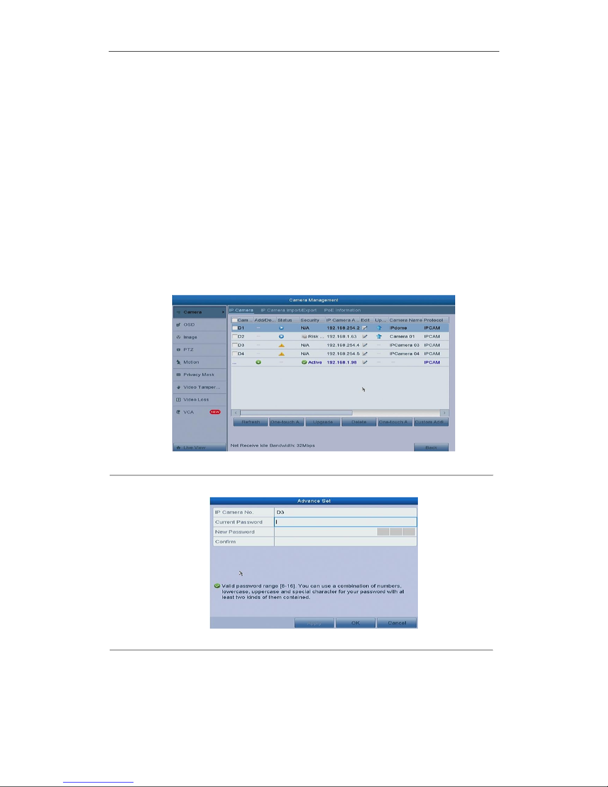
1. Select the Add IP Camera option from the right-click menu in live view mode or click Menu> Camera>
Camera to enter the IP camera management interface.
For the IP camera detected online in the same network segment, the Security status shows whether it is
active or inactive.
Figure 2. 15 IP Camera Management Interface
2. Click the inactive icon of the camera to enter the following interface to activate it.
Figure 2. 16 Activate the Camera
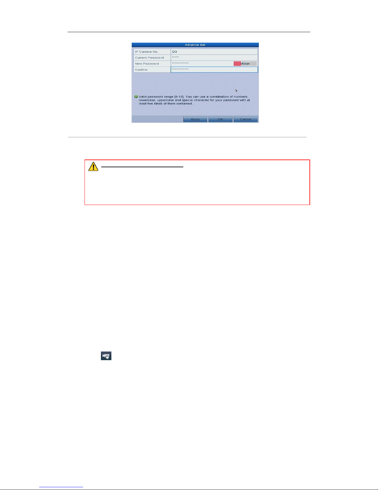
3. Set the password of the camera to activate it.
Page 34
User Manual of Network Video Recorder
33
Figure 2. 17 Set New Password
Create New Password: If the admin password is not used, you must create the new password for the
camera and confirm it.
STRONG PASSWORD RECOMMENDED– We highly recommend you create a strong password of
your own choosing (using a minimum of 8 characters, including upper case letters, lower case
letters, numbers, and special characters) in order to increase the security of your product. And
we recommend you reset your password regularly, especially in the high security system,
resetting the password monthly or weekly can better protect your product.
4. Click OK to finish the acitavting of the IP camera. And the security status of camera will be changed to
Active.
2.5.4 Adding the Online IP Cameras
Purpose:
The main function of the NVR is to connect the network cameras and record the video got from it. So before you
can get a live view or record of the video, you should add the network cameras to the connection list of the
device.
Before you start:
Ensure the network connection is valid and correct. For detailed checking and configuring of the network, please
see Chapter Checking Network Traffic and Chapter Configuring Network Detection.
OPTION 1:
Steps:
1. Click to select an idle window in the live view mode.
2. Click the icon in the center of the windw to pop up the adding IP camera interface.
Page 35
User Manual of Network Video Recorder
34
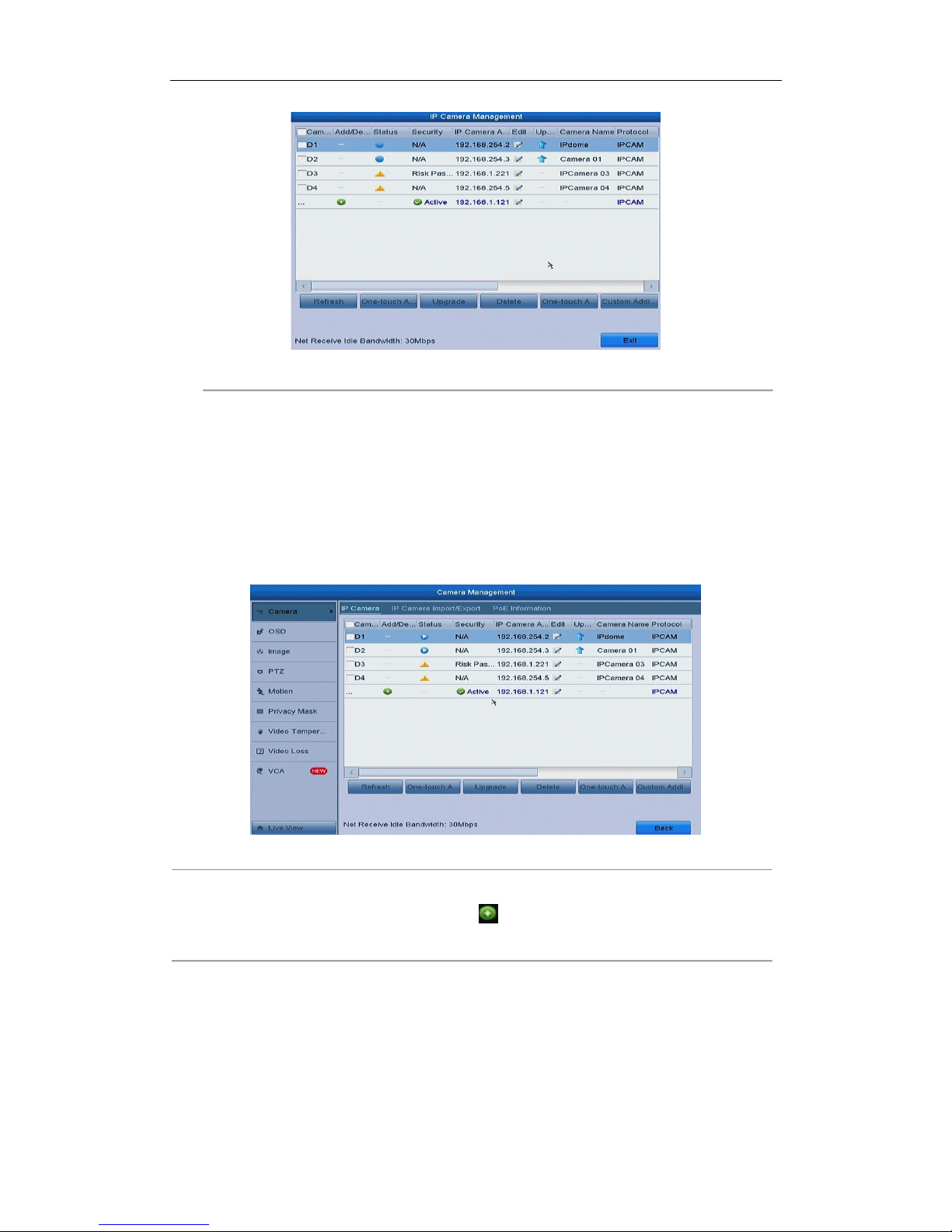
Figure 2. 18 Quick Adding IP Camera Interface
3. Select the detected IP camera and click the Add button to add it directly, and you can click the Search
button to refresh the online IP camera manually.
Or you can choose to custom add the IP camera by editing the parameters in the corresponding textfiled
and then click the Add button to add it.
OPTION 2:
Steps:
1. Select the Add IP Camera option from the right-click menu in live view mode or click Menu> Camera>
Camera to enter the IP camera management interface.
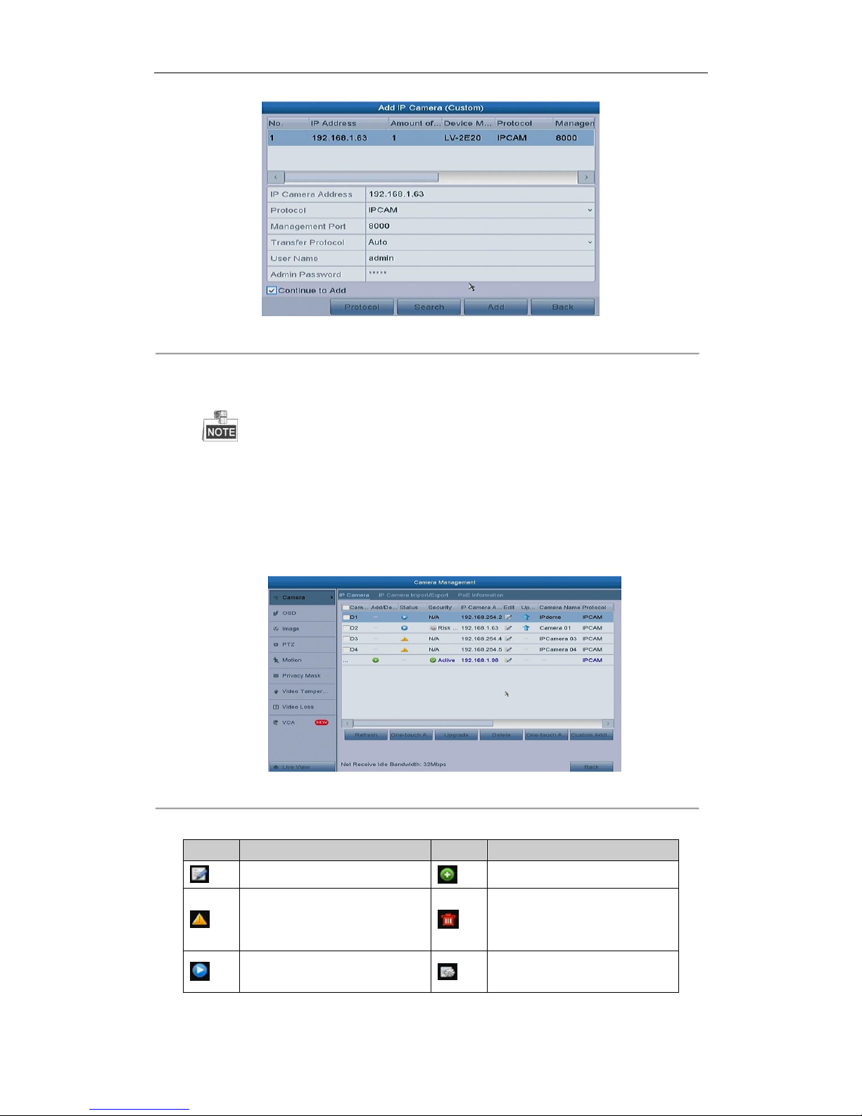
Figure 2. 19 Adding IP Camera Interface
2. The online cameras with same network segment will be detected and displayed in the camera list.
3. Select the IP camera from the list and click the button to add the camera. Or you can click the
One-touch Adding button to add all cameras from the list.
OPTION 3:
Steps:
1) On the IP Camera Management interface, click the Custom Adding button to pop up the Add IP Camera
(Custom) interface.
Page 36
User Manual of Network Video Recorder
35
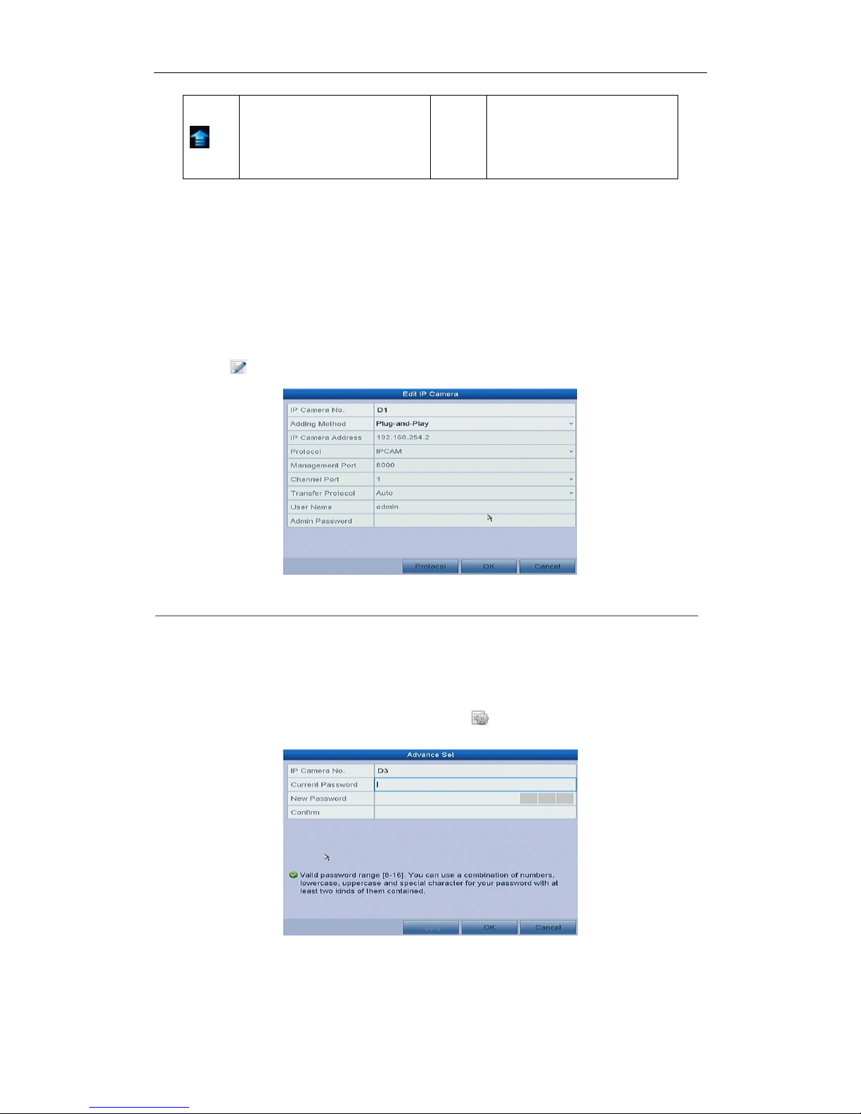
Figure 2. 20 Custom Adding IP Camera Interface
2) You can edit the IP address, protocol, management port, and other information of the IP camera to be
added.
If the IP camera to add has not been actiavted, you can activate it from the IP camera list on the camera
management interface.
3) (Optional) Check the checkbox of Continue to Add to add other IP cameras.
4) Click Add to add the camera.
For the successfully added IP cameras, the Security status shows the security level of the password of
camera: strong password, weak password and risk password.
Figure 2. 21 Successfully Added IP Cameras
Table 2. 1 Explanation of the icons
Icon
Explanation
Icon
Explanation
Edit basic parameters of the camera
Add the detected IP camera.
The camera is disconnected; you can
click the icon to get the exception
information of camera.
Delete the IP camera
Play the live video of the connected
camera.
Advanced settings of the camera.
Page 37
User Manual of Network Video Recorder
36
Upgrade the connected IP camera.
Security
Show the security status of the
camera to be active/inactive or the
password strength
(strong/weak/risk)
2.5.5 Editing the Connected IP cameras and Configuring
Customized Protocols
After the adding of the IP cameras, the basic information of the camera lists in the page, you can configure the
basic setting of the IP cameras.
Steps:
1. Click the icon to edit the parameters; you can edit the IP address, protocol and other parameters.
Figure 2. 22 Edit the Parameters
Channel Port: If the connected device is an encoding device with multiple channels, you can choose the
channel to connect by selecting the channel port No. in the dropdown list.
2. Click OK to save the settings and exit the editing interface.
To edit advanced parameters:
1. Drag the horizontal scroll bar to the right side and click the icon.
2. You can edit the network information and the password of the camera.
Figure 2. 23 Password Configuration of the Camera
3. Click OK to save the settings and exit the interface.
Configuring the customized protocols
Purpose:
Page 38
User Manual of Network Video Recorder
37
To connect the network cameras which are not configured with the standard protocols, you can configure the
customized protocols for them.
Steps:
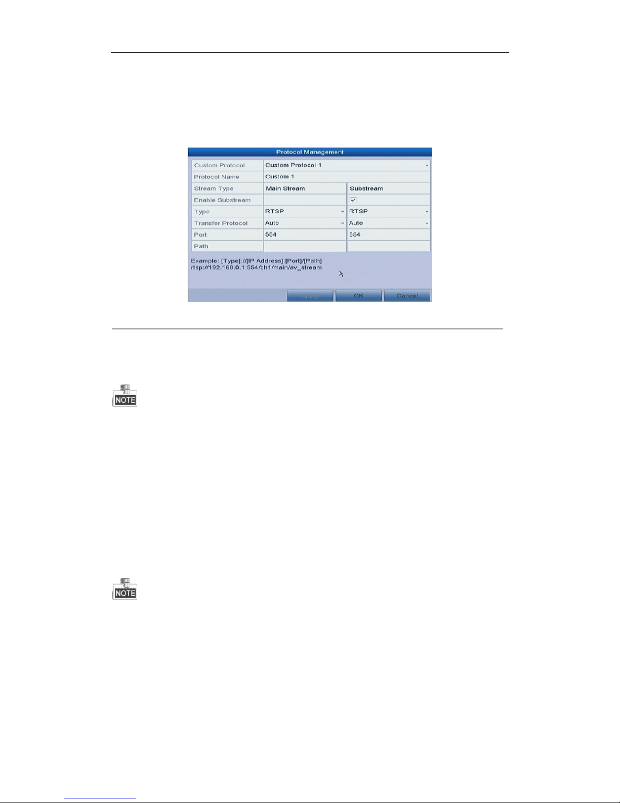
1. Click the Protocol button in the custom adding IP camera interface to enter the protocol management
interface.
Figure 2. 24 Protocol Management Interface
There are 16 customized protocols provided in the system, you can edit the protocol name; and choose
whether to enable the sub-stream.
2. Choose the protocol type of transmission and choose the transfer protocols.
Before customizing the protocol for the network camera, you have to contact the manufacturer of the network
camera to consult the URL (uniform resource locator) for getting main stream and sub-stream.
The format of the URL is: [Type]://[IP Address of the network camera]:[Port]/[Path].
Example: rtsp://192.168.1.55:554/ch1/main/av_stream.
Protocol Name: Edit the name for the custom protocol.
Enable Substream: If the network camera does not support sub-stream or the sub-stream is not needed
leave the checkbox empty.
Type: The network camera adopting custom protocol must support getting stream through standard RTSP.
Transfer Protocol: Select the transfer protocol for the custom protocol.
Port: Set the port No. for the custom protocol.
Path: Set the resource path for the custom protocol. E.g., ch1/main/av_stream.
The protocol type and the transfer protocols must be supported by the connected network camera.
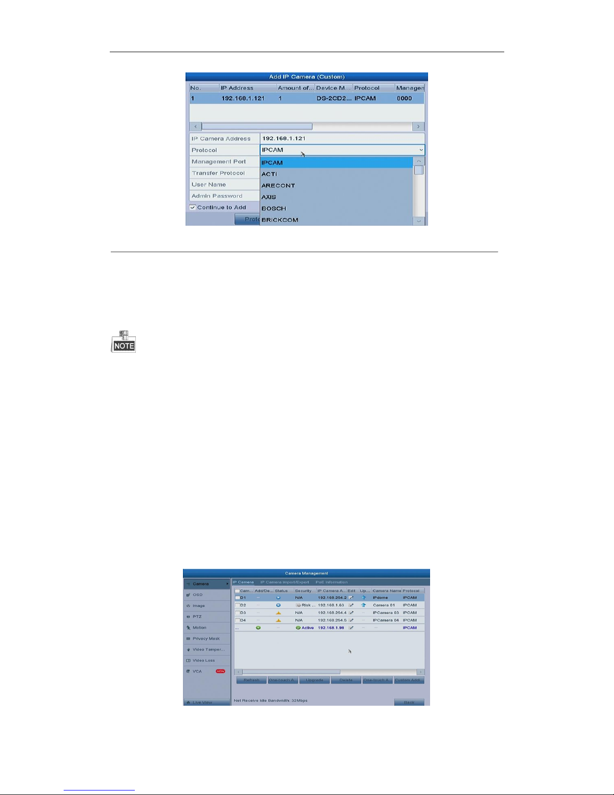
After adding the customized protocols, you can see the protocol name is listed in the dropdown list, please refer
to Figure 2. 25.
Page 39
User Manual of Network Video Recorder
38
Figure 2. 25 Protocol Setting
3. Choose the protocols you just added to validate the connection of the network camera.
2.5.6 Editing IP Cameras Connected to the PoE Interfaces
This chapter is only applicable for the models with POE interface.
The PoE interfaces enables the NVR system to pass electrical power safely, along with data, on Ethernet cabling to
the connected network cameras.
The POE series provides up to 16 PoE interfaces which can connect to 16 network cameras directly; and if you
disable the PoE interface, you can also connect to the online network cameras. And the PoE interface supports
the Plug-and-Play function.
Example:
As for 8-ch NVR, when you want to connect 2 online cameras and connect 6 network cameras via PoE interfaces,
you must disable 2 PoE interfaces in the Edit IP Camera menu.
To add Cameras for NVR supporting PoE function:
Before you start:
Connect the network cameras via the PoE interfaces.
Steps:
1. Enter the Camera Management interface.
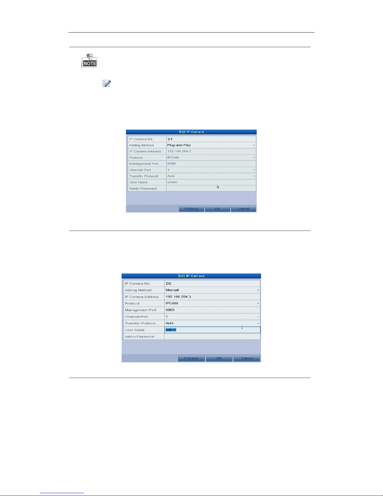
Menu> Camera> Camera
Figure 2. 26 List of Connected Cameras
Page 40
User Manual of Network Video Recorder
39
The cameras connecting to the PoE interface cannot be deleted in this menu.
2. Click the button, and select the Adding Method in the drop-down list.
• Plug-and-Play: It means that the camera is connected to the PoE interface, so in this case, the
parameters of the camera can’t be edited. The IP address of the camera can only be edited in the
Network Configuration interface, see Chapter10.1 Configuring General Settings for detailed
information.
Figure 2. 27 Edit IP Camera Interface - Plug-and-Play
• Manual: You can disable the PoE interface by selecting the manual while the current channel can be
used as a normal channel and the parameters can also be edited.
Input the IP address, the user name and password of administrator manually, and click OK to add the IP
camera.
Figure 2. 28 Edit IP Camera Interface - Manual
Page 41

User Manual of Network Video Recorder
40
Chapter 3 Live View
Page 42
User Manual of Network Video Recorder
41
3.1 Introduction of Live View
Live view shows you the video image getting from each camera in real time. The NVR automatically enters Live
View mode when powered on. It is also at the very top of the menu hierarchy, thus pressing the ESC many times
(depending on which menu you’re on) brings you to the Live View mode.
Live View Icons
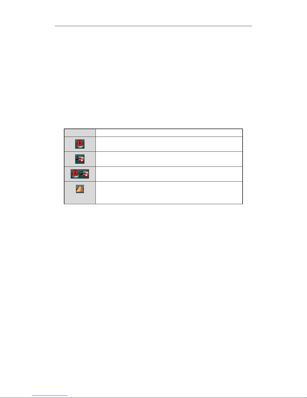
In the live view mode, there are icons at the upper-right of the screen for each channel, showing the status of the
record and alarm in the channel, so that you can know whether the channel is recorded, or whether there are
alarms occur as soon as possible.
Table 3. 1 Description of Live View Icons
Icons
Description
Alarm (video loss, video tampering, motion detection, sensor alarm or VCA alarm)
Record (manual record, continuous record, motion detection , sensor alarm or
VCA alarm triggered record)
Alarm & Record
Event/Exception (motion detection, sensor alarm, VCA alarm or exception
information, appears at the lower-left corner of the screen. Please refer to
Chapter 8.6 Setting Alarm Response Actions for details.)
Page 43
User Manual of Network Video Recorder
42
3.2 Operations in Live View Mode
In live view mode, there are many functions provided. The functions are listed below.
• Single Screen: showing only one screen on the monitor.
• Multi-screen: showing multiple screens on the monitor simultaneously.
• Auto-switch: the screen is auto switched to the next one. And you must set the dwell time for each screen
on the configuration menu before enabling the auto-switch.
Menu > Configuration > Live View > Dwell Time.
• Start Recording: continuous record and motion detection record are supported.
• Output Mode: select the output mode to Standard, Bright, Gentle or Vivid.
• Add IP Camera: the shortcut to the IP camera management interface.
• Playback: playback the recorded videos for current day.
3.2.1 Using the Mouse in Live View
Table 3. 2 Mouse Operation in Live View
Name
Description
Common Menu
Quick access to the sub-menus which you frequently visit.
Menu
Enter the main menu of the system by right clicking the mouse.
Single Screen
Switch to the single full screen by choosing channel number from the dropdown
list.
Multi-screen
Adjust the screen layout by choosing from the dropdown list.
Previous Screen
Switch to the previous screen.
Next Screen
Switch to the next screen.
Start/Stop Auto-switch
Enable/disable the auto-switch of the screens.
Start Recording
Start continuous recording or motion detection recording of all channels.
Add IP Camera
Enter the IP Camera Management interface, and manage the cameras.
Playback
Enter the playback interface and start playing back the video of the selected
channel immediately.
Output Mode
Four modes of output supported, including Standard, Bright, Gentle and Vivid.
The dwell time of the live view configuration must be set before using Start Auto-switch.
If the corresponding camera supports intelligent function, the Reboot Intelligence option is included when
right-clicking mouse on this camera.
Figure 3. 1 Right-click Menu
The right-click menu varies according to different models, please refer to the actual GUI menu of the device.
Page 44
User Manual of Network Video Recorder
43
3.2.2 Quick Setting Toolbar in Live View Mode
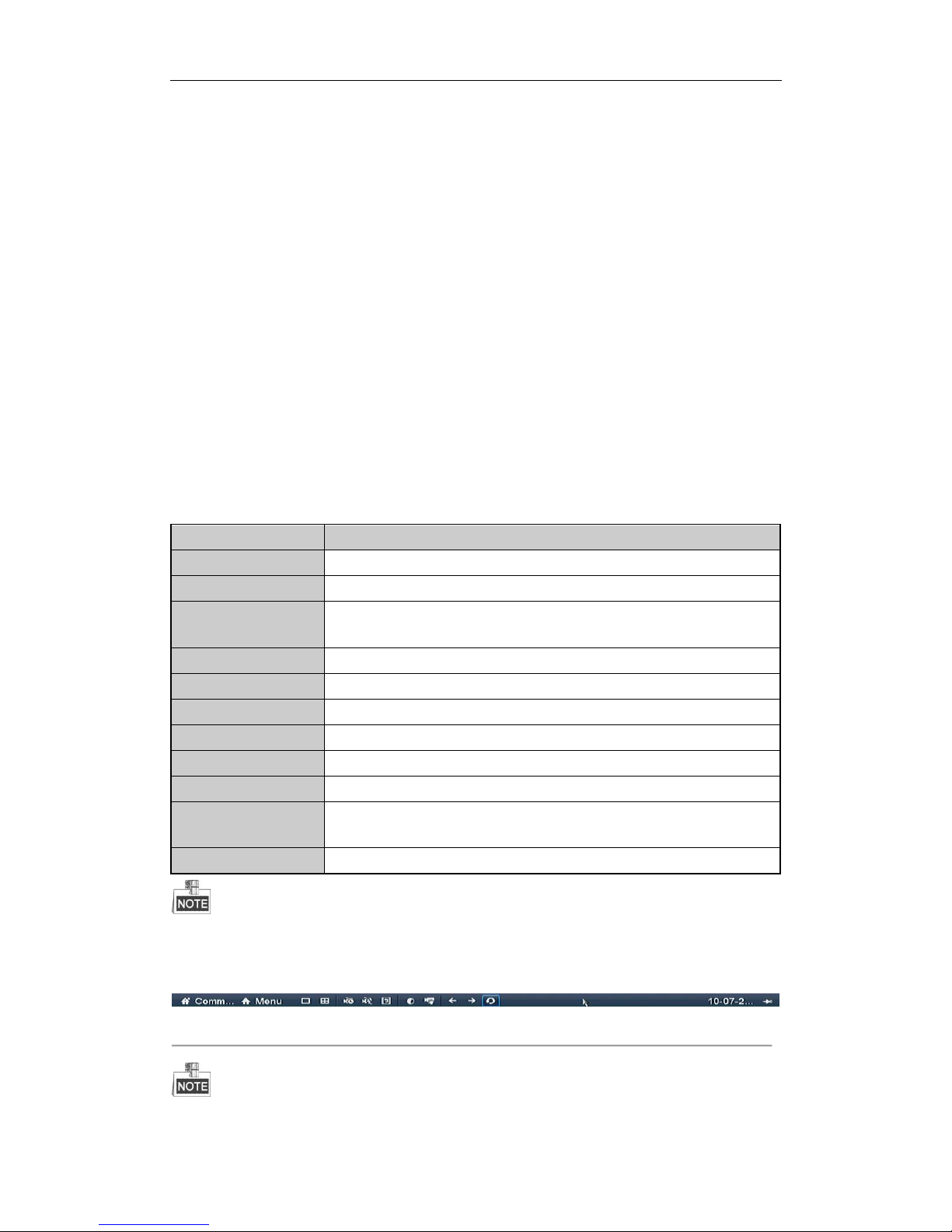
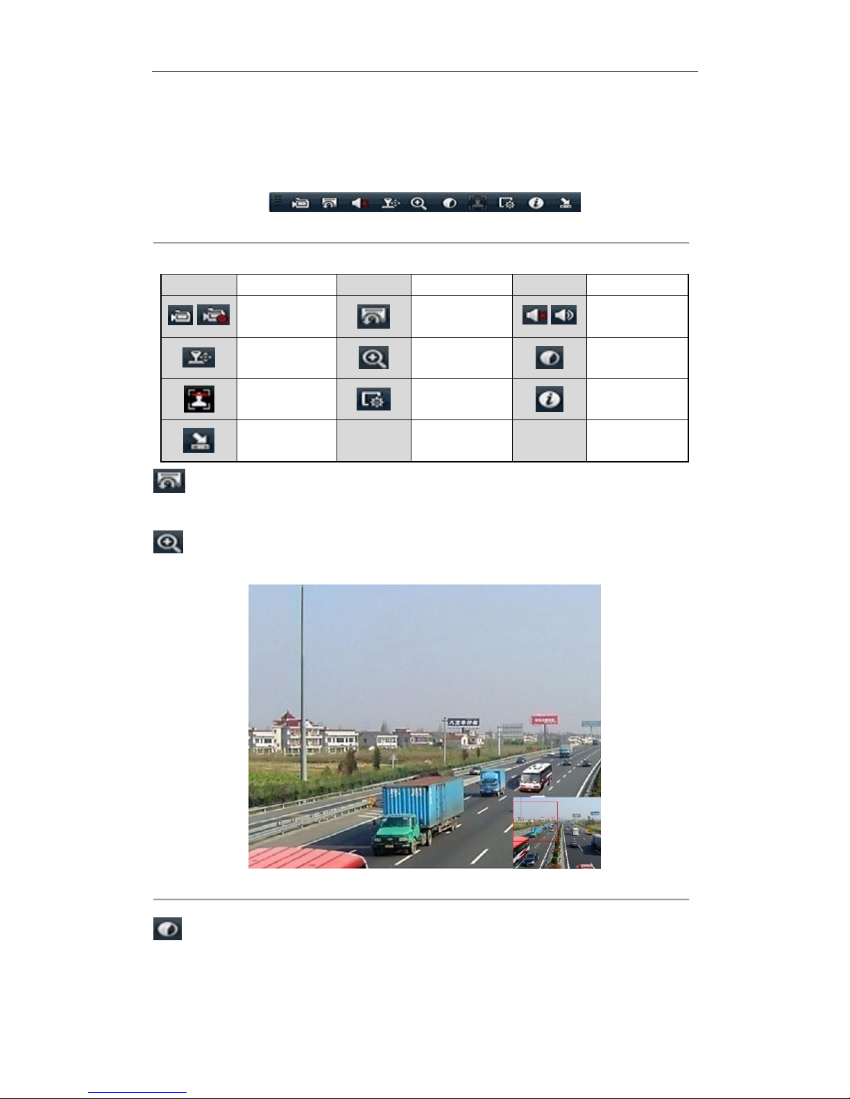
On the screen of each channel, there is a quick setting toolbar which shows when you single click the mouse in
the corresponding screen.
Figure 3. 2 Quick Setting Toolbar
Table 3. 3 Description of Quick Setting Toolbar Icons
Icon
Description
Icon
Description
Icon
Description
/
Enable/Disable
Manual Record
Instant Playback
/
Mute/Audio on
PTZ Control
Digital Zoom
Image Settings
Face Detection
Live View Strategy
Information
Close
Instant Playback only shows the record in last five minutes. If no record is found, it means there is no
record during the last five minutes.
Digital Zoom can zoom in the selected area to the full screen. You can left-click and draw to select the
area to zoom in, as shown in Figure 3. 3.
Figure 3. 3 Digital Zoom
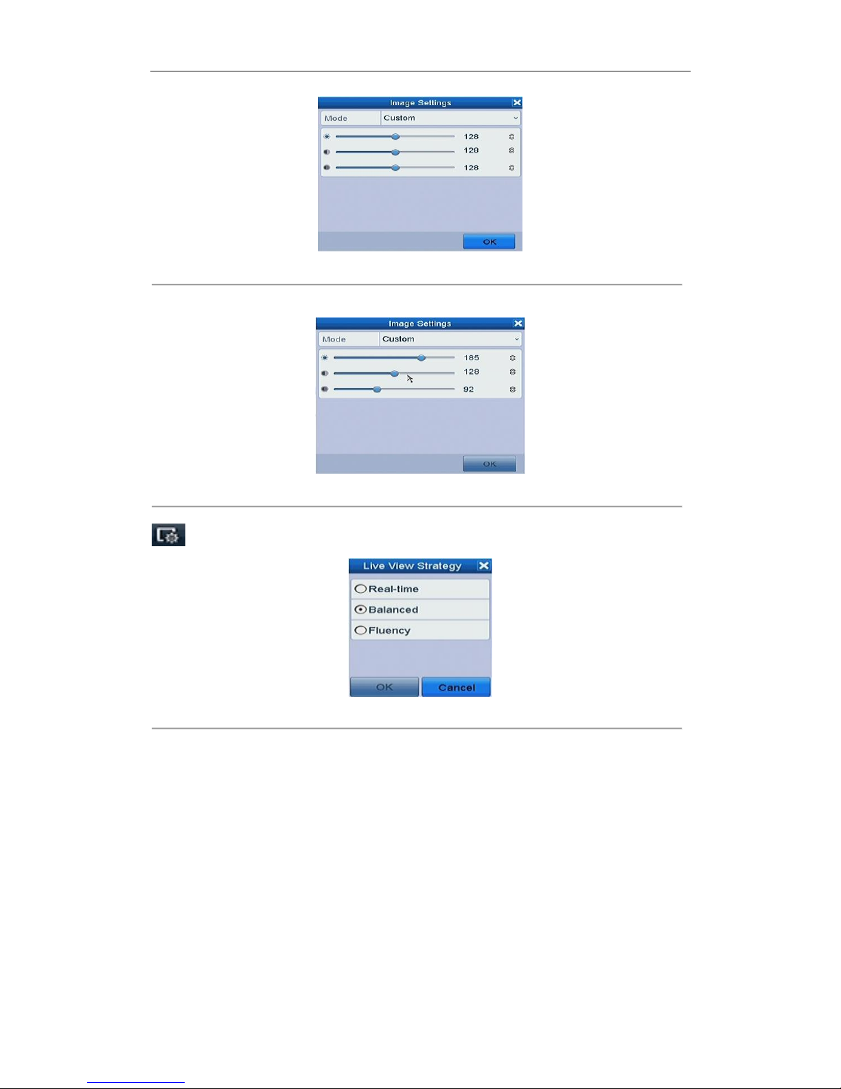
Image Settings icon can be selected to enter the Image Settings menu.
Page 45
User Manual of Network Video Recorder
44
Figure 3. 4 Image Settings- Preset
You can set the image parameters like brightness, contrast, saturation and hue.
Figure 3. 5 Image Settings- Customize
Live V iew Strategy can be selected to set strategy, including Real-time, Balanced, Fluency.
Figure 3. 6 Live View Strategy
3.3 Adjusting Live View Settings
Purpose:
Live View settings can be customized according to different needs. You can configure the output interface, dwell
time for screen to be shown, mute or turning on the audio, the screen number for each channel, etc.
Steps:
1. Enter the Live View Settings interface.
Menu > Configuration > Live View
Page 46
User Manual of Network Video Recorder
45
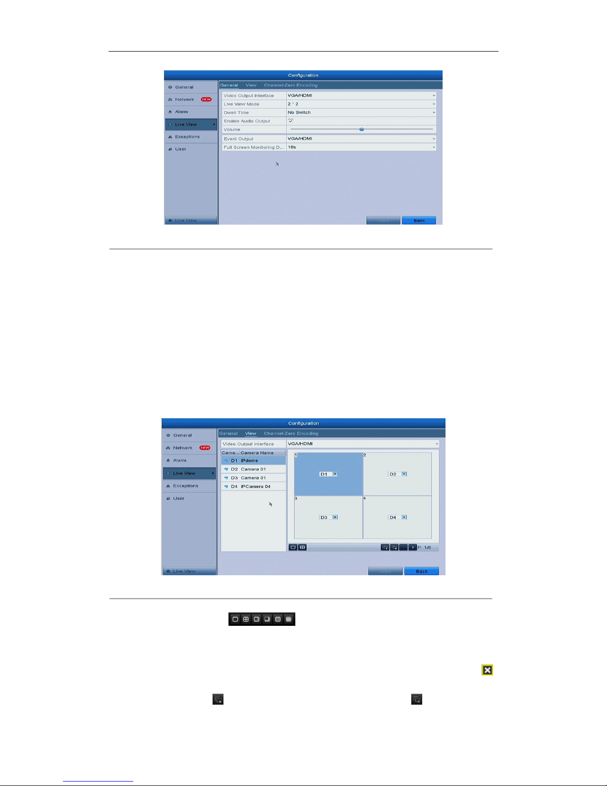
Figure 3. 7 Live View-General
The settings available in this menu include:
• Video Output Interface: Designates the output to configure the settings for, and only VGA/ HDMI
TM
is
selectable by default.
• Live View Mode: Designates the display mode to be used for Live View.
• Dwell Time: The time in seconds to dwell between switching of channels when enabling auto-switch in
Live View.
• Enable Audio Output: Enables/disables audio output for the selected video output.
• Volume: Adjust the volume of live view, playback and two-way audio for the selected output interface.
• Event Output: Designates the output to show event video.
• Full Screen Monitoring Dwell Time: The time in seconds to show alarm event screen.
2. Setting Cameras Order
Figure 3. 8 Live View- Camera Order
1) Select a View mode in .
2) Select the small window, and double-click on the channel number to display the channel on the
window.
If you do not want the camera to be displayed on the live view interface, click the corresponding
to stop it.
You can also click button to start live view for all the channels and click to stop all the live
Page 47
User Manual of Network Video Recorder
46
view.
3) Click the Apply button to save the setting.
3.4 Channel-zero Encoding
Purpose:
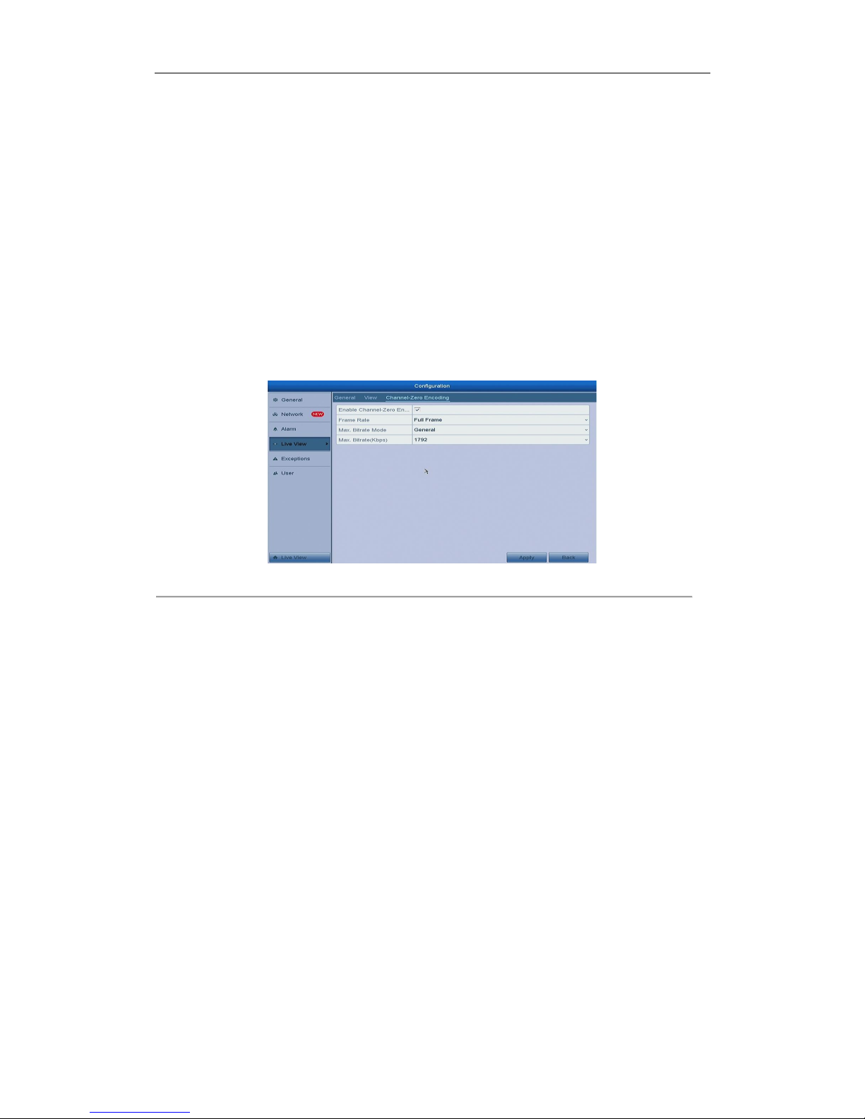
Sometimes you need to get a remote view of many channels in real time from web browser or CMS (Client
Management System) software, in order to decrease the bandwidth requirement without affecting the image
quality, channel-zero encoding is supported as an option for you.
Steps:
1. Enter the Live View Settings interface.
Menu > Configuration > Live View
2. Select the Channel-Zero Encoding tab.
Figure 3. 9 Live View- Channel-Zero Encoding
3. Check the checkbox after Enable Channel Zero Encoding.
4. Configure the Frame Rate, Max. Bitrate Mode and Max. Bitrate.
After you set the Channel-Zero encoding, you can get a view in the remote client or web browser of 16 channels
in one screen.
Page 48

User Manual of Network Video Recorder
47
Chapter 4 PTZ Controls
Page 49
User Manual of Network Video Recorder
48
4.1 Configuring PTZ Settings
Purpose:
Follow the procedure to set the parameters for PTZ. The configuring of the PTZ parameters should be done
before you control the PTZ camera.
Steps:
1. Enter the PTZ Settings interface.
Menu > Camera > PTZ
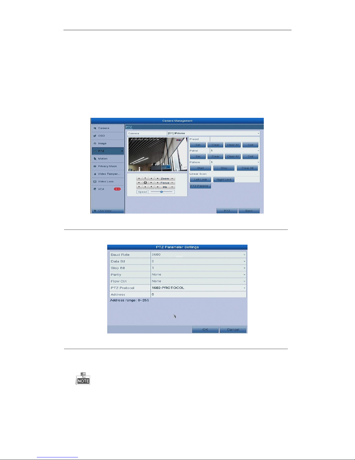
Figure 4. 1 PTZ Settings
2. Click the RS-485 Settings button to set the PTZ parameters.
Figure 4. 2 PTZ- General
3. Choose the camera for PTZ setting in the Camera dropdown list.
4. Enter the parameters of the PTZ camera.
All the parameters should be exactly the same as the PTZ camera parameters.
5. Click Apply button to save the settings.
Page 50
User Manual of Network Video Recorder
49
4.2 Setting PTZ Presets, Patrols & Patterns
Before you start:
Please make sure that the presets, patrols and patterns should be supported by PTZ protocols.
4.2.1 Customizing Presets
Purpose:
Follow the steps to set the Preset location which you want the PTZ camera to point to when an event takes place.
Steps:
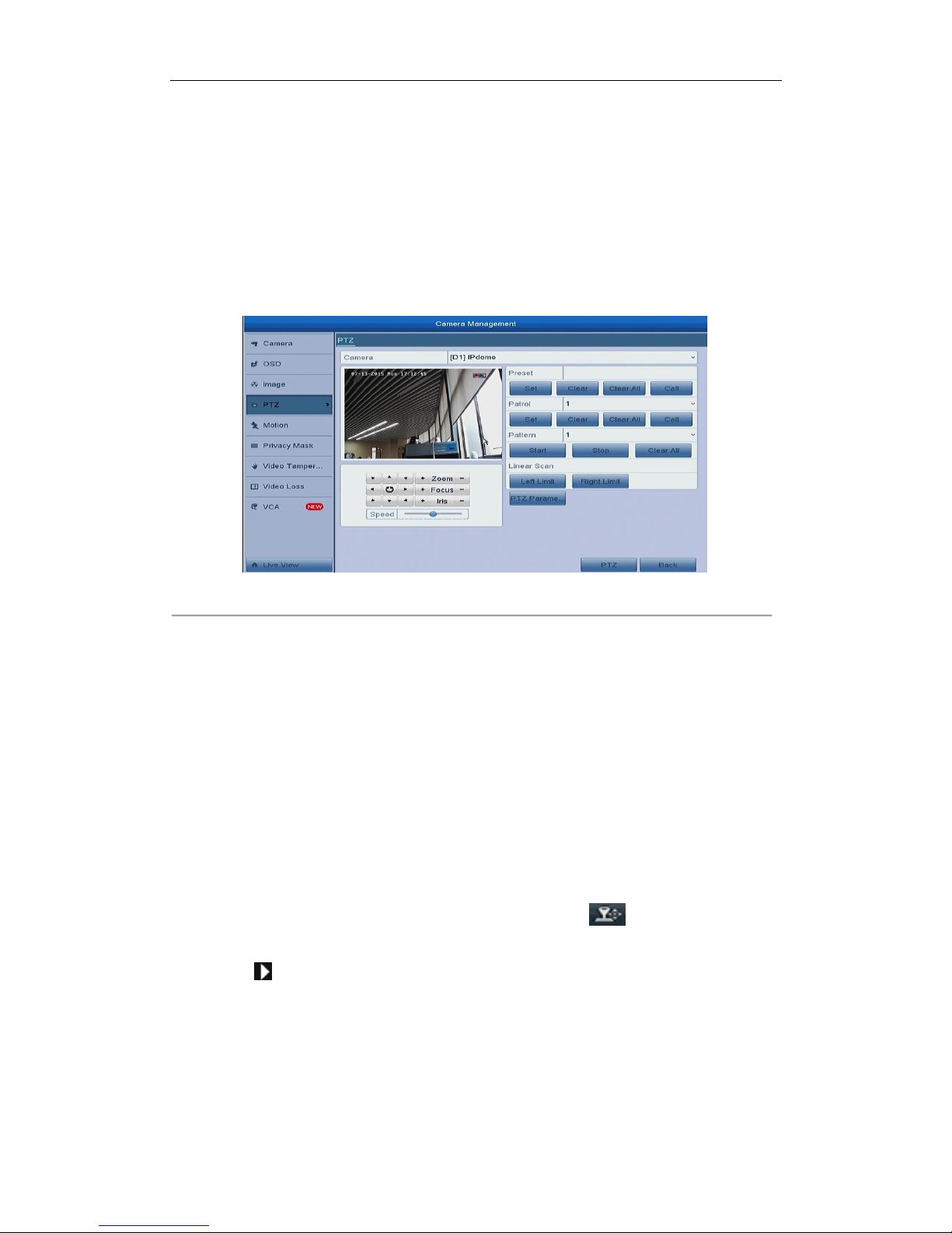
1. Enter the PTZ Control interface.
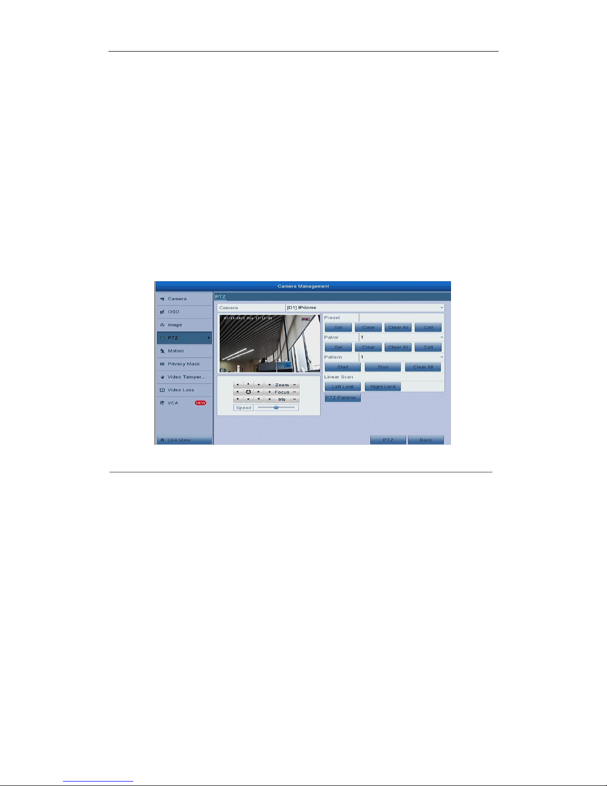
Menu > Camera > PTZ
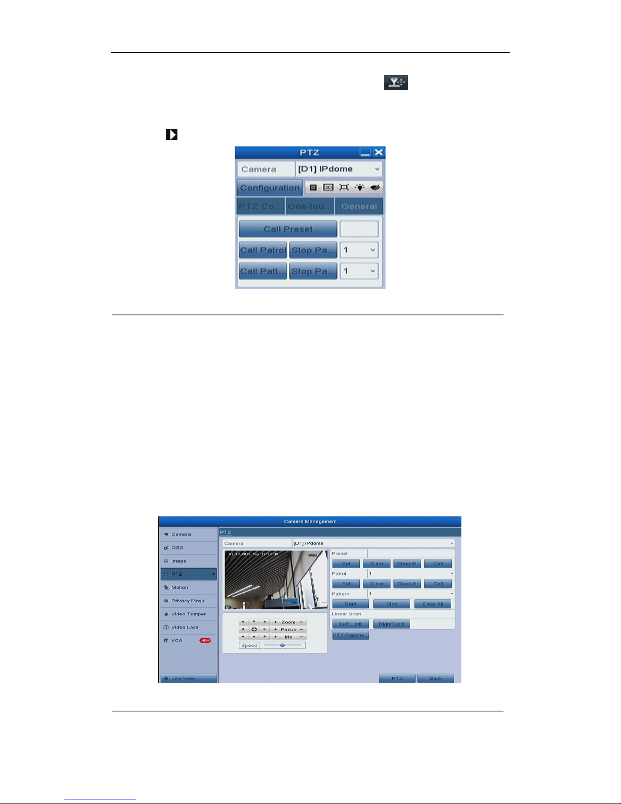
Figure 4. 3 PTZ Settings
2. Use the directional button to wheel the camera to the location where you want to set preset; and the zoom
and focus operations can be recorded in the preset as well.
3. Enter the preset No. (1~255) in the preset text field, and click the Set button to link the location to the
preset.
Repeat the steps2-3 to save more presets.
You can click the Clear button to clear the location information of the preset, or click the Clear All button to
clear the location information of all the presets.
4.2.2 Calling Presets
Purpose:
This feature enables the camera to point to a specified position such as a window when an event takes place.
Steps:
1. Click the button PTZ in the lower-right corner of the PTZ setting interface;
Page 51
User Manual of Network Video Recorder
50
Or press the PTZ button on the front panel or click the PTZ Control icon in the quick setting bar, or
select the PTZ option in the right-click menu to show the PTZ control panel.
2. Choose Camera in the dropdown list.
3. Click the button to show the general settings of the PTZ control.
Figure 4. 4 PTZ Panel - General
4. Click to enter the preset No. in the corresponding text field.
5. Click the Call Preset button to call it.
4.2.3 Customizing Patrols
Purpose:
Patrols can be set to move the PTZ to different key points and have it stay there for a set duration before moving
on to the next key point. The key points are corresponding to the presets. The presets can be set following the
steps above in Customizing Presets.
Steps:
1. Enter the PTZ Control interface.
Menu > Camera > PTZ
Figure 4. 5 PTZ Settings
2. Select patrol No. in the drop-down list of patrol.
Page 52
User Manual of Network Video Recorder
51
3. Click the Set button to add key points for the patrol.
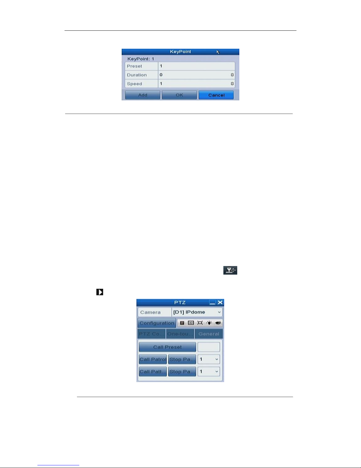
Figure 4. 6 Key point Configuration
4. Configure key point parameters, such as the key point No., duration of staying for one key point and speed
of patrol. The key point is corresponding to the preset. The Key Point No. determines the order at which
the PTZ will follow while cycling through the patrol. The Duration refers to the time span to stay at the
corresponding key point. The Speed defines the speed at which the PTZ will move from one key point to
the next.
5. Click the Add button to add the next key point to the patrol, and you can click the OK button to save the
key point to the patrol.
You can delete all the key points by clicking the Clear button for the selected patrol, or click the Clear All
button to delete all the key pints for all patrols.
4.2.4 Calling Patrols
Purpose:
Calling a patrol makes the PTZ to move according the predefined patrol path.
Steps:
1. Click the button PTZ in the lower-right corner of the PTZ setting interface;
Or press the PTZ button on the front panel or click the PTZ Control icon in the quick setting bar, or
select the PTZ option in the right-click menu to show the PTZ control panel.
2. Click the button to show the general settings of the PTZ control.
Figure 4. 7 PTZ Panel - General
3. Select a patrol in the dropdown list and click the Call Patrol button to call it.
4. You can click the Stop Patrol button to stop calling it.
Page 53
User Manual of Network Video Recorder
52
4.2.5 Customizing Patterns
Purpose:
Patterns can be set by recording the movement of the PTZ. You can call the pattern to make the PTZ movement
according to the predefined path.
Steps:
1. Enter the PTZ Control interface.
Menu > Camera > PTZ
Figure 4. 8 PTZ Settings
2. Choose pattern number in the dropdown list.
3. Click the Start button and click corresponding buttons in the control panel to move the PTZ camera, and
click the Stop button to stop it.
The movement of the PTZ is recorded as the pattern.
4.2.6 Calling Patterns
Purpose:
Follow the procedure to move the PTZ camera according to the predefined patterns.
Steps:
1. Click the button PTZ in the lower-right corner of the PTZ setting interface;
Or press the PTZ button on the front panel or click the PTZ Control icon in the quick setting bar, or
select the PTZ option in the right-click menu to show the PTZ control panel.
2. Click the button to show the general settings of the PTZ control.
Page 54
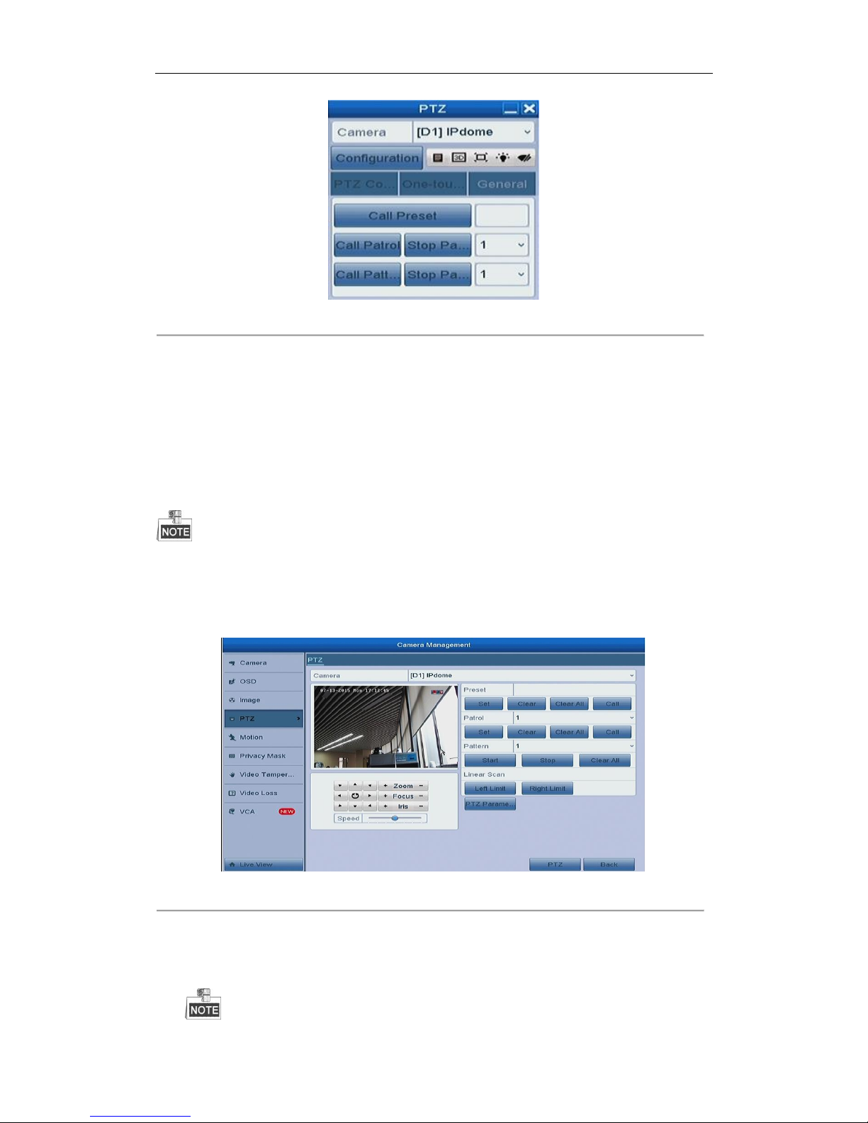
User Manual of Network Video Recorder
53
Figure 4. 9 PTZ Panel - General
3. Click the Call Pattern button to call it.
4. Click the Stop Pattern button to stop calling it.
4.2.7 Customizing Linear Scan Limit
Purpose:
The Linear Scan can be enabled to trigger the scan in the horizantal direction in the predefined range.
This function is supported by some certain models.
Steps:
1. Enter the PTZ Control interface.
Menu > Camera > PTZ
Figure 4. 10 PTZ Settings
2. Use the directional button to wheel the camera to the location where you want to set the limit, and click
the Left Limit or Right Limit button to link the location to the corresponding limit.
Page 55
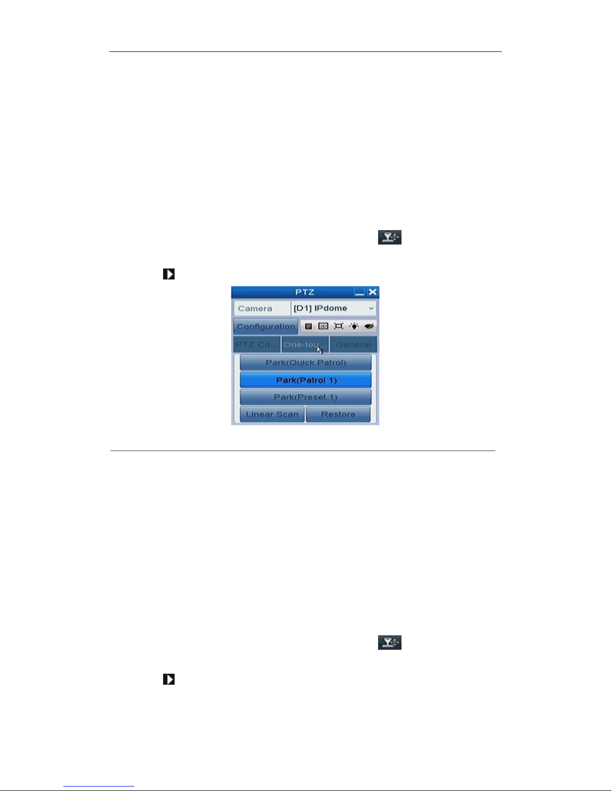
User Manual of Network Video Recorder
54
The speed dome starts linear scan from the left limit to the right limit, and you must set the left limit
on the left side of the right limit, as well the angle from the left limit to the right limit should be no
more than 180º.
4.2.8 Calling Linear Scan
Purpose:
Follow the procedure to call the linear scan in the predefined scan range.
Steps:
1. Click the button PTZ in the lower-right corner of the PTZ setting interface;
Or press the PTZ button on the front panel or click the PTZ Control icon in the quick setting bar to
enter the PTZ setting menu in live view mode.
2. Click the button to show the one-touch function of the PTZ control.
Figure 4. 11 PTZ Panel - One-touch
3. Click Linear Scan button to start the linear scan and click the Linear Scan button again to stop it.
You can click the Restore button to clear the defined left limit and right limit data and the dome needs to
reboot to make settings take effect.
4.2.9 One-touch Park
Purpose:
For some certain model of the speed dome, it can be configured to start a predefined park action (scan, preset,
patrol and etc.) automatically after a period of inactivity (park time).
Steps:
1. Click the button PTZ in the lower-right corner of the PTZ setting interface;
Or press the PTZ button on the front panel or click the PTZ Control icon in the quick setting bar to
enter the PTZ setting menu in live view mode.
2. Click the button to show the one-touch function of the PTZ control.
Page 56
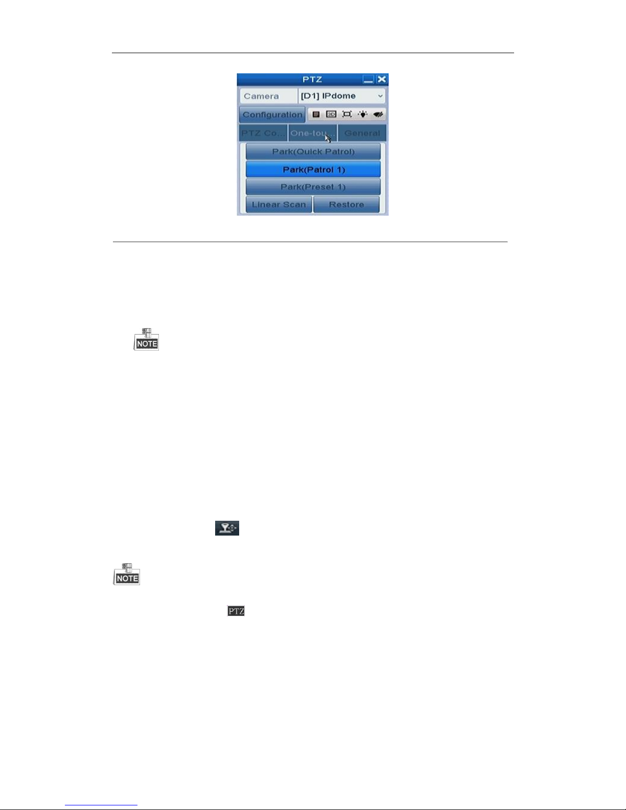
User Manual of Network Video Recorder
55
Figure 4. 12 PTZ Panel - One-touch
3. There are 3 one-touch park types selectable, click the corresponding button to activate the park action.
Park (Quick Patrol): The dome starts patrol from the predefined preset 1 to preset 32 in order after the park
time. The undefined preset will be skipped.
Park (Patrol 1): The dome starts move according to the predefined patrol 1 path after the park time.
Park (Preset 1): The dome moves to the predefined preset 1 location after the park time.
The park time can only be set through the speed dome configuration interface, by default the value is 5s.
4. Click the button again to inactivate it.
4.3 PTZ Control Panel
To enter the PTZ control panel, there are two ways supported.
OPTION 1:
In the PTZ settings interface, click the PTZ button on the lower-right corner which is next to the Back button.
OPTION 2:
In the Live View mode, you can press the PTZ Control button on the front panel or on the remote control, or
choose the PTZ Control icon , or select the PTZ option in the right-click menu.
Click the Configuration button on the control panel, and you can enter the PTZ Settings interface.
In PTZ control mode, the PTZ panel will be displayed when a mouse is connected with the device. If no
mouse is connected, the icon appears in the lower-left corner of the window, indicating that this
camera is in PTZ control mode.
Page 57
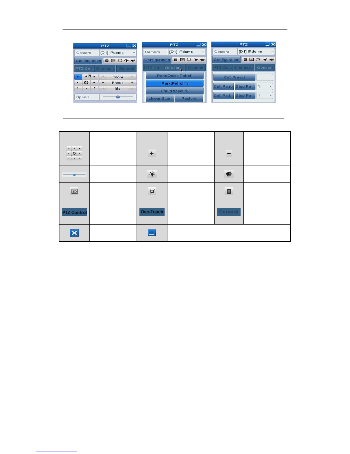
User Manual of Network Video Recorder
56
Figure 4. 13 PTZ Panel
Table 4. 1 Description of the PTZ panel icons
Icon
Description
Icon
Description
Icon
Description
Direction button and
the auto-cycle
button
Zoom+, Focus+, Iris+
Zoom-, Focus-, Iris-
The speed of the PTZ
movement
Light on/off
Wiper on/off
3D-Zoom
Image Centralization
Menu
Switch to the PTZ
control interface
Switch to the
one-touch control
interface
Switch to the
general settings
interface
Exit
Minimize windows
Page 58

User Manual of Network Video Recorder
57
Chapter 5 Recording Settings
Page 59
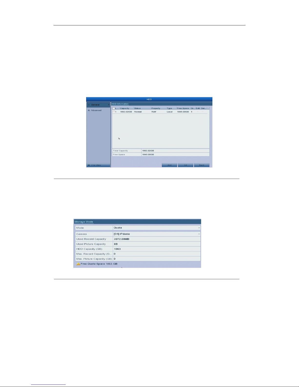
User Manual of Network Video Recorder
58
5.1 Configuring Parameters
Purpose:
By configuring the parameters you can define the parameters which affect the image quality, such as the
transmission stream type, the resolution and so on.
Before you start:
1. Make sure that the HDD has already been installed. If not, please install a HDD and initialize it. (Menu >
HDD > General)
Figure 5. 1 HDD- General
2. Check the storage mode of the HDD.
1) Click Advanced to check the storage mode of the HDD.
2) If the HDD mode is Quota, please set the maximum record capacity For detailed information, see
Chapter 11.3 Configuring Quota Mode.
3) If the HDD mode is Group, you should set the HDD group.
Figure 5. 2 HDD- Advanced
Steps:
1. Enter the Record settings interface to configure the recording parameters:
Menu > Record > Parameters
Page 60
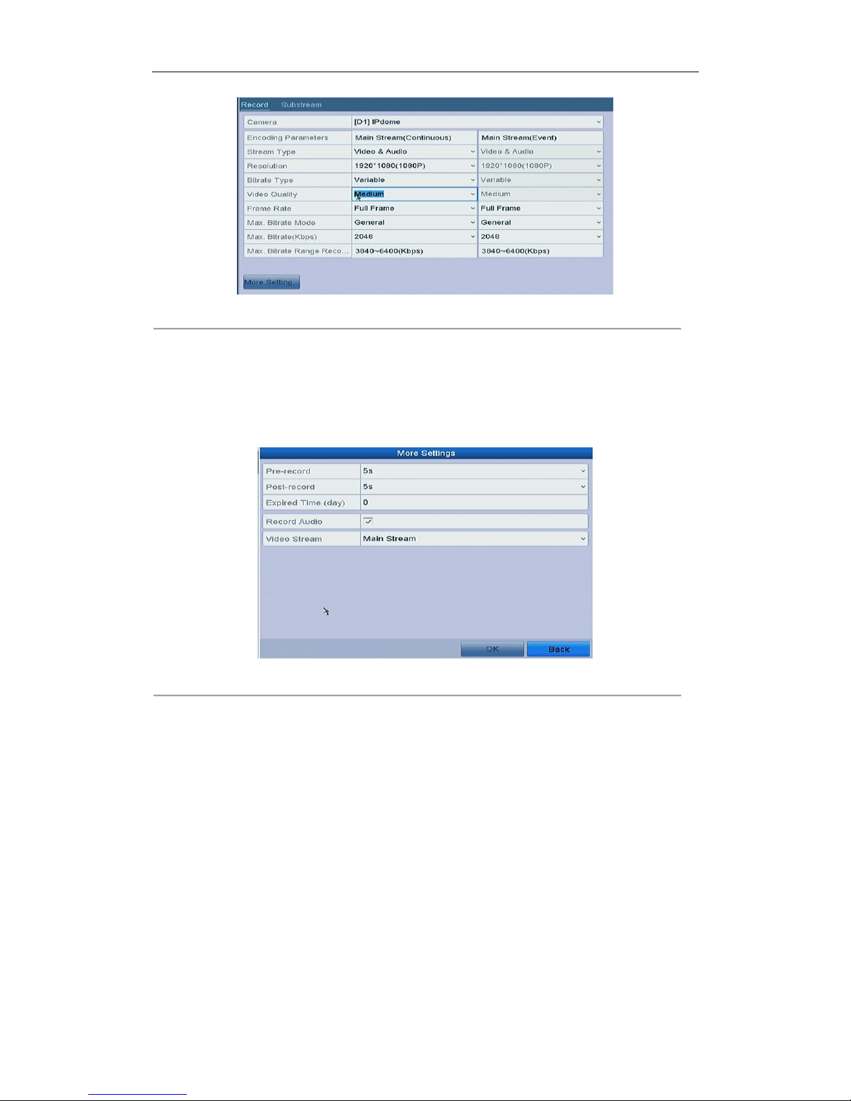
User Manual of Network Video Recorder
59
Figure 5. 3 Recording Parameters
2. Parameters Setting for Recording
1) Select Record tab page to configure. You can configure the stream type, the resolution, and other
parameters on your demand.
2) Click the More Settings button to set the advanced parameters for recording and then click OK button
to finish editing.
Figure 5. 4 Recording Parameters-More Settings
• Pre-record: The time you set to record before the scheduled time or event. For example, when an
alarm triggered the recording at 10:00, if you set the pre-record time as 5 seconds, the camera
records it at 9:59:55.
• Post-record: The time you set to record after the event or the scheduled time. For example, when
an alarm triggered the recording ends at 11:00, if you set the post-record time as 5 seconds, it
records till 11:00:05.
• Expired Time: The expired time is the longest time for a record file to be kept in the HDD, if the
deadline is reached, the file will be deleted. You can set the expired time to 0, and then the file will
not be deleted. The actual keeping time for the file should be determined by the capacity of the
HDD.
• Record Audio: Check the checkbox to enable or disable audio recording.
• Video Stream: Main stream and sub-stream are selectable for recording. When you select
sub-stream, you can record for a longer time with the same storage space.
3) Click Apply to save the settings.
Page 61
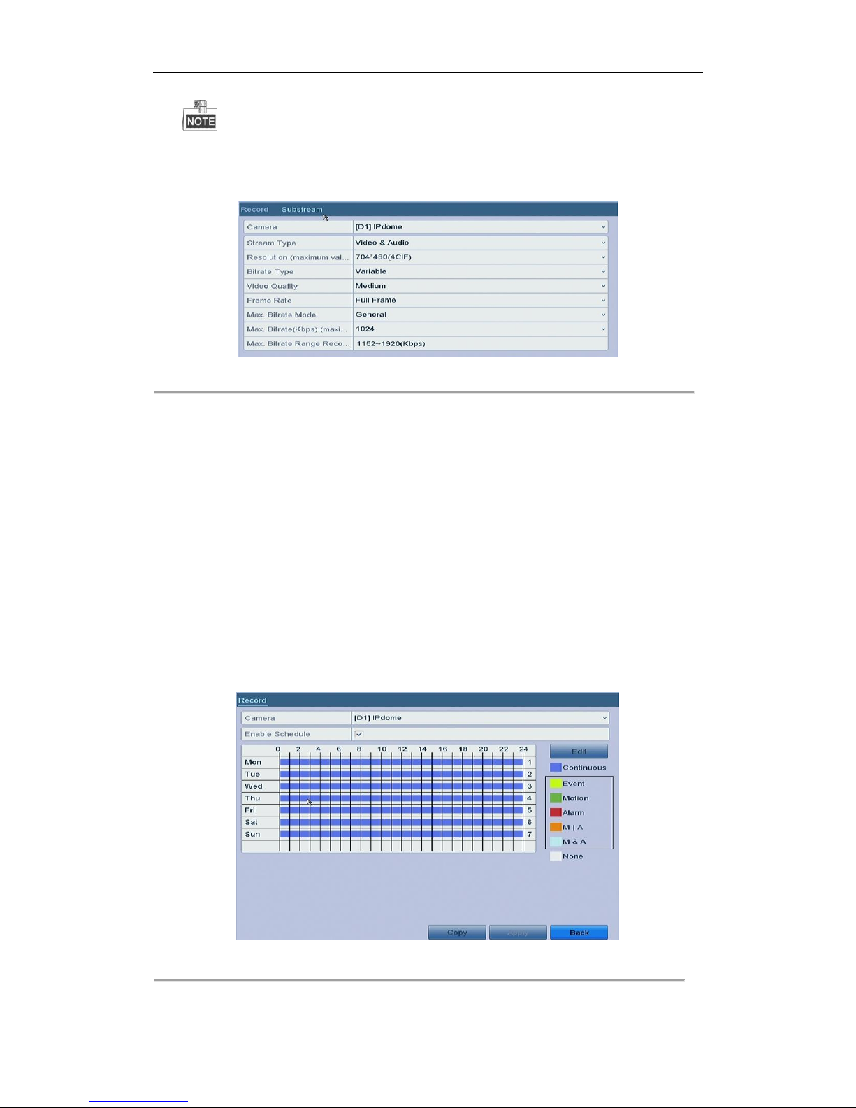
User Manual of Network Video Recorder
60
The parameters of Main Stream (Event) are read-only.
3. Parameters Settings for Sub-stream
1) Enter the Sub-stream tab page.
Figure 5. 5 Sub-stream Parameters
2) Configure the parameters of the camera.
3) Click Apply to save the settings.
5.2 Configuring Recording Schedule
Purpose:
Set the recording schedule, and then the camera automatically starts/stops recording according to the configured
schedule.
Steps:
1. Enter the Record Schedule interface.
Menu > Record > Schedule
2. Configure Record Schedule
1) Select Record Schedule.
Figure 5. 6 Record Schedule
Different recording types are marked in different color icons.
Page 62
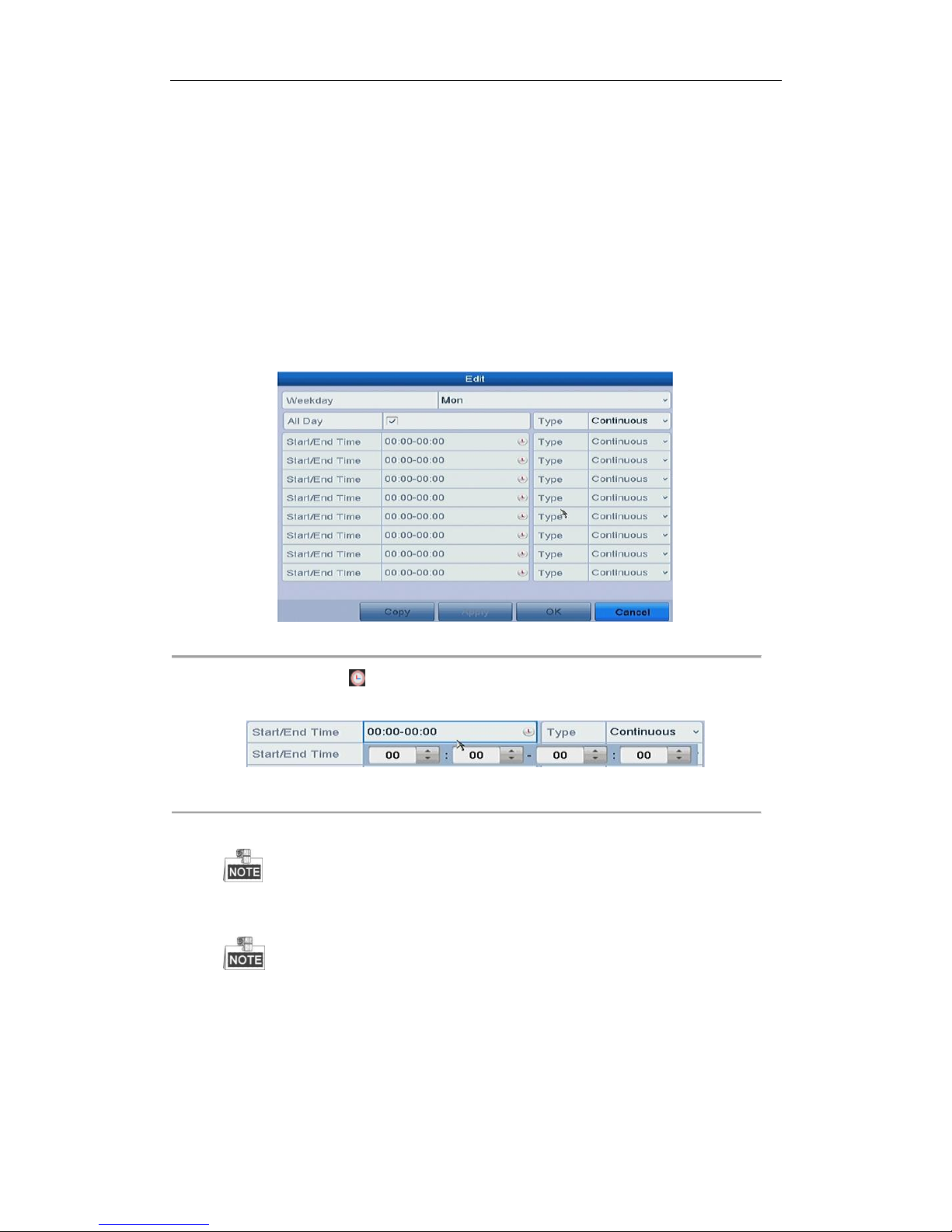
User Manual of Network Video Recorder
61
Continous: scheduled recording.
Event: recording triggered by all event triggered alarm.
Motion: recording triggered by motion detection.
Alarm: recording triggered by alarm.
M/A: recording triggered by either motion detection or alarm.
M&A: recording triggered by motion detection and alarm.
2) Choose the camera you want to configure.
3) Select the check box after the Enable Schedule item.
4) Click Edit button or click on the color icon under the edit button and draw the schedule line on the
panel.
Edit the schedule:
I. In the message box, you can choose the day to which you want to set schedule.
Figure 5. 7 Recording Schedule Interface
You can click the button to set the accurate time of the schedule.
II. To schedule an all-day recording, check the checkbox after the All Day item.
Figure 5. 8 Edit Schedule
III. To arrange other schedule, leave the All Day checkbox blank and set the Start/End time.
Up to 8 periods can be configured for each day. And the time periods cannot be overlapped each other.
IV. Select the record type in the dropdown list.
To enable Motion, Alarm, M | A (motion or alarm), M & A (motion and alarm) and VCA (Video
Content Analysis) triggered recording and capture, you must configure the motion detection
settings, alarm input settings or VCA settings as well. For detailed information, refer to Chapter
8.1, Chapter 8.2 and Chapter 5.5.
The VCA settings are only available to the smart IP cameras.
Repeat the above edit schedule steps to schedule recording for other days in the week. You can click
Page 63
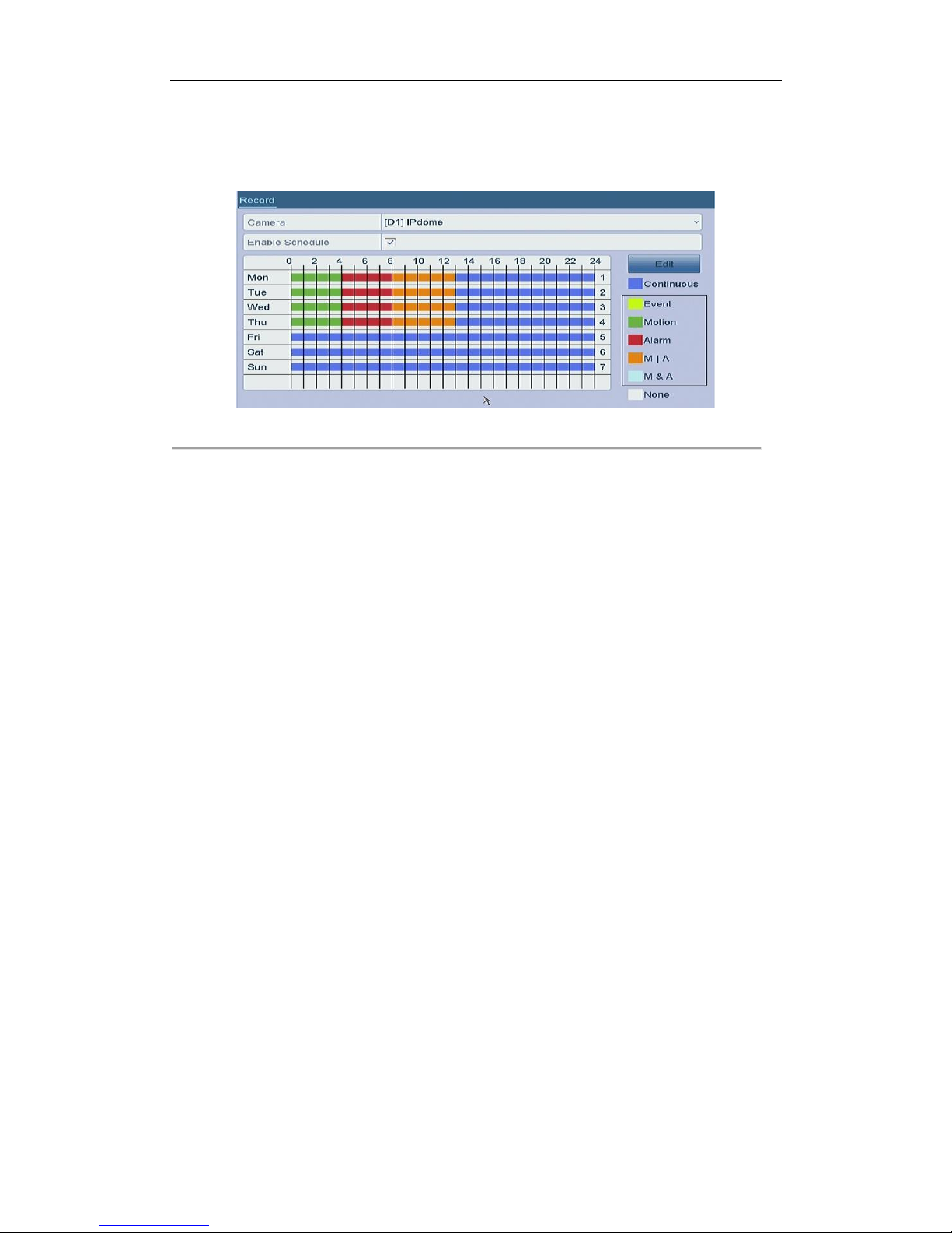
User Manual of Network Video Recorder
62
Copy to enter the Copy to interface to copy the schedule settings to other days
V. Click Apply in the Record Schedule interface to save the settings.
Draw the schedule:
I. Click on the color icons, you can choose the schedule type as continuous or event.
Figure 5. 9 Draw the Schedule
II. Click the Apply button to validate the settings.
3. (Optional) If the settings can also be used to other channels, click Copy, and then choose the channel to
which you want to copy.
4. Click Apply to save the settings.
5.3 Configuring Motion Detection Recording
Purpose:
Follow the steps to set the motion detection parameters. In the live view mode, once a motion detection event
takes place, the NVR can analyze it and do many actions to handle it. Enabling motion detection function can
trigger certain channels to start recording, or trigger full screen monitoring, audio warning, notify the surveillance
center and so on. In this chapter, you can follow the steps to schedule a record which triggered by the detected
motion.
Steps:
1. Enter the Motion Detection interface.
Menu > Camera > Motion
2. Configure Motion Detection
1) Choose camera you want to configure.
2) Check the checkbox after Enable Motion Detection.
3) Drag and draw the area for motion detection by mouse. If you want to set the motion detection for all
the area shot by the camera, click Full Screen. To clear the motion detection area, click Clear.
Page 64
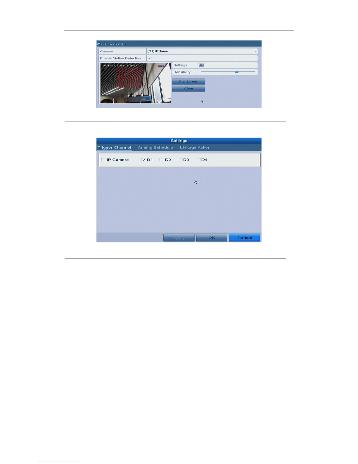
User Manual of Network Video Recorder
63
Figure 5. 10 Motion Detection- Mask
4) Click Settings, and the message box for channel information pop up.
Figure 5. 11 Motion Detection Handling
5) Select the channels which you want the motion detection event to trigger recording.
6) Click Apply to save the settings.
7) Click OK to back to the upper level menu.
8) Exit the Motion Detection menu.
3. Edit the Motion Detection Record Schedule. For the detailed information of schedule configuration, see
Chapter 5.2 Configuring Recording Schedule.
5.4 Configuring Alarm Triggered Recording
Purpose:
Follow the procedure to configure alarm triggered recording.
Steps:
1. Enter the Alarm setting interface.
Menu > Configuration > Alarm
Page 65
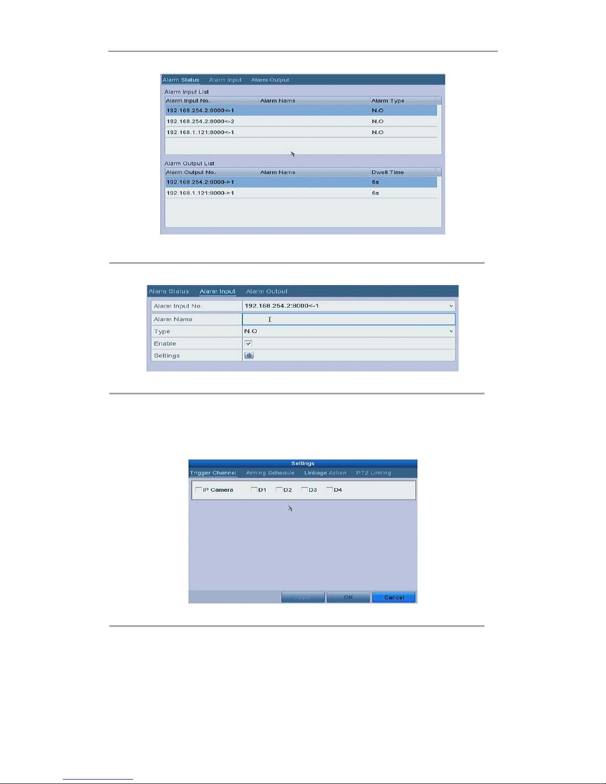
User Manual of Network Video Recorder
64
Figure 5. 12 Alarm Settings
2. Click Alarm Input tab and set the alarm parameters.
Figure 5. 13 Alarm Settings- Alarm Input
1) Select Alarm Input number and configure alarm parameters.
2) Choose N.O (normally open) or N.C (normally closed) for alarm type.
3) Check the checkbox for Enable.
4) Click Settings.
Figure 5. 14 Alarm Settings
5) Choose the alarm triggered recording channel.
6) Check the checkbox to select channel.
7) Click Apply to save settings.
8) Click OK to back to the upper level menu.
Repeat the above steps to configure other alarm input parameters.
Page 66
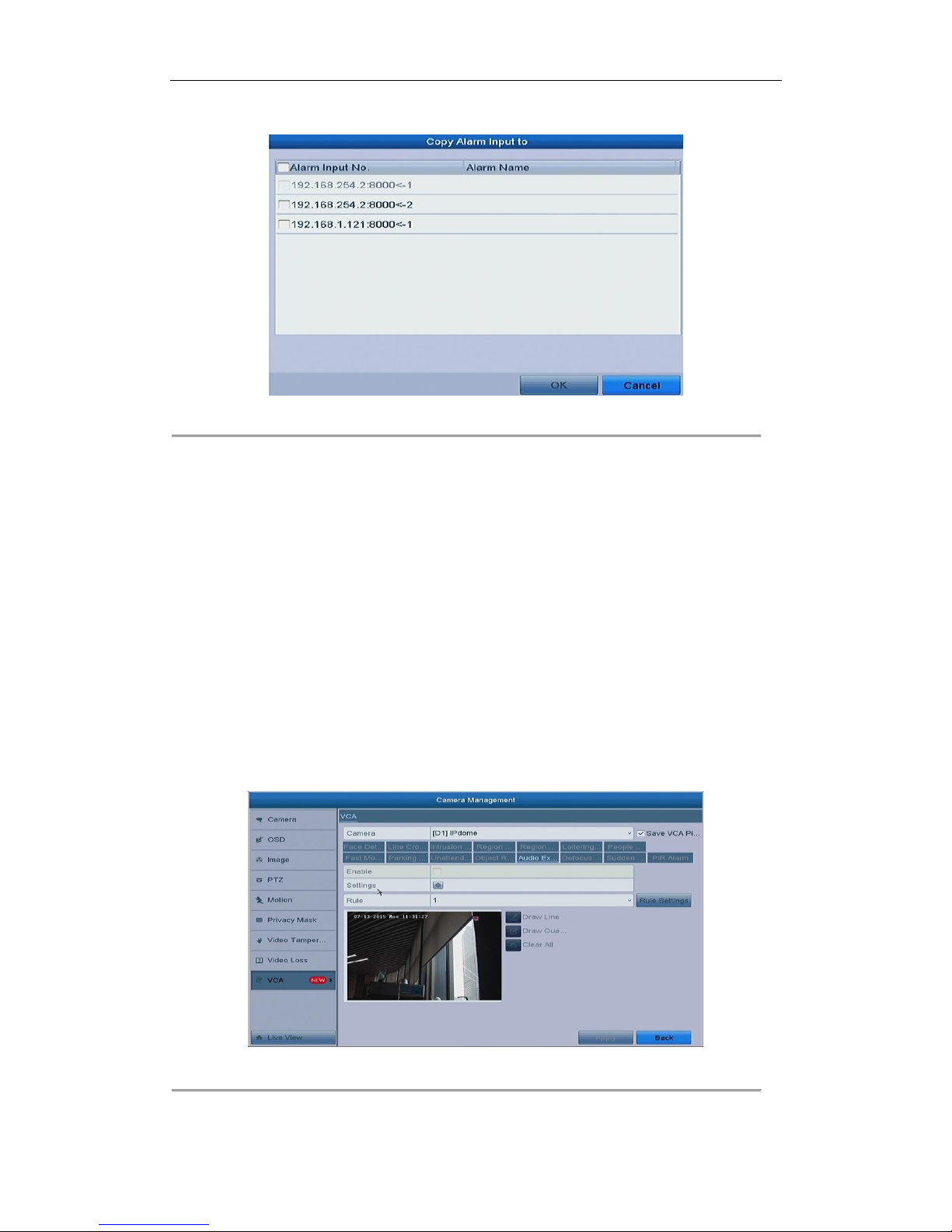
User Manual of Network Video Recorder
65
If the settings can also be applied to other alarm inputs, click Copy and choose the alarm input number.
Figure 5. 15 Copy Alarm Input
3. Edit the Alarm triggered record in the Record Schedule setting interface. For the detailed information of
schedule configuration, see Chapter 5.2 Configuring Recording Schedule.
5.5 Configuring VCA Event Recording
Purpose:
The event triggered recording can be configured through the menu. Then events include the motion detection,
alarm and VCA events (face detection/face capture, line crossing detection, intrusion detection, region entrance
detection, region exiting detection, loitering detection, people gathering detection, fast moving detection,
parking detection, unattended baggage detection, object removal detection, audio loss exception detection,
sudden change of sound intensity detection, and defocus detection).
Steps:
1. Enter the VCA settings interface and select a camera for the VCA settings.
Menu > Camera > VCA
Figure 5. 16 VCA Settings
2. Configure the detection rules for VCA events. For details, see the step 2 in Chapter 9 VCA Alarm.
Page 67
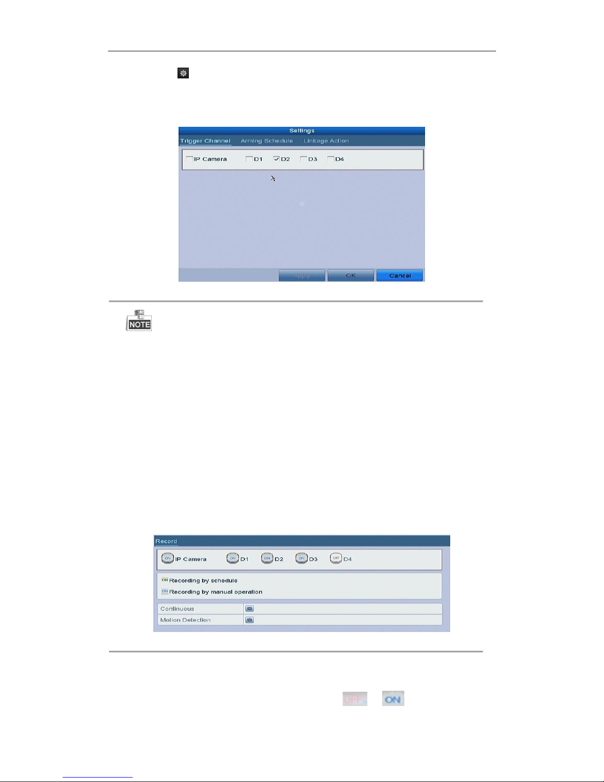
User Manual of Network Video Recorder
66
3. Click the icon to configure the alarm linkage actions for the VCA events.
Select Trigger Channel tab and select one or more channels which will start to record when VCA alarm is
triggered.
Click Apply to save the settings
Figure 5. 17 Set Trigger Camera of VCA Alarm
The PTZ Linking function is only available for the VCA settings of IP cameras.
4. Enter Record Schedule settings interface (Menu > Record > Schedule > Record Schedule), and then set VCA
as the record type. For details, see step 2 in Chapter 5.2 Configuring Recording Schedule.
5.6 Manual Recording
Purpose:
Follow the steps to set parameters for the manual record. Using manual record, you need to manually cancel the
record. The manual recording is prior to the scheduled recording.
Steps:
1. Enter the Manual settings interface.
Menu > Manual
Or press the REC/SHOT button on the front panel.
Figure 5. 18 Manual Record
2. Enable the Manual Record.
1) Select Record on the left bar.
2) Click the status button before camera number to change to .
Page 68
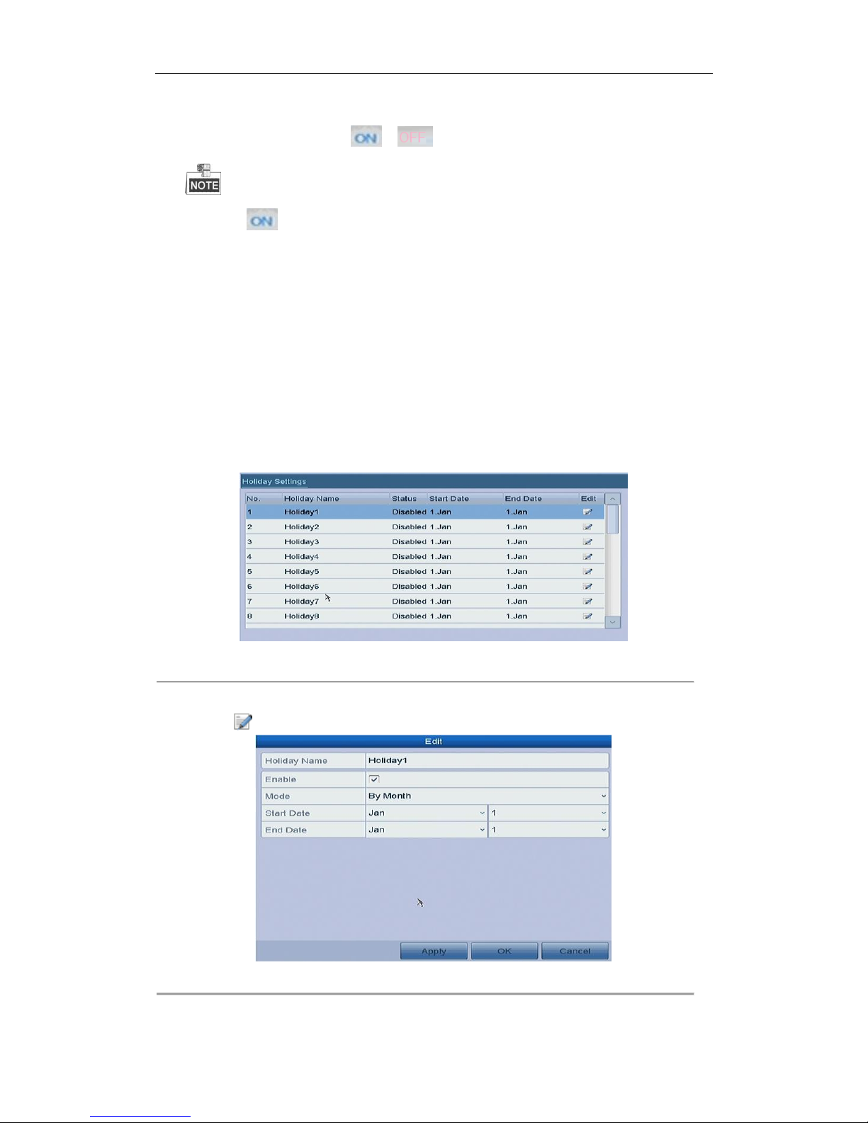
User Manual of Network Video Recorder
67
3. Disable manual record.
Click the status button to change to .
Green icon means that the channel is configured the record schedule. After rebooting, all the
manual records enabled will be canceled.
5.7 Configuring Holiday Recording
Purpose:
Follow the steps to configure the record schedule on holiday for that year. You may want to have different plan for
recording on holiday.
Steps:
1. Enter the Record setting interface.
Menu > Record > Holiday
Figure 5. 19 Holiday Settings
2. Enable Edit Holiday schedule.
1) Click to enter the Edit interface.
Figure 5. 20 Edit Holiday Settings
2) Check the checkbox after Enable Holiday.
Page 69
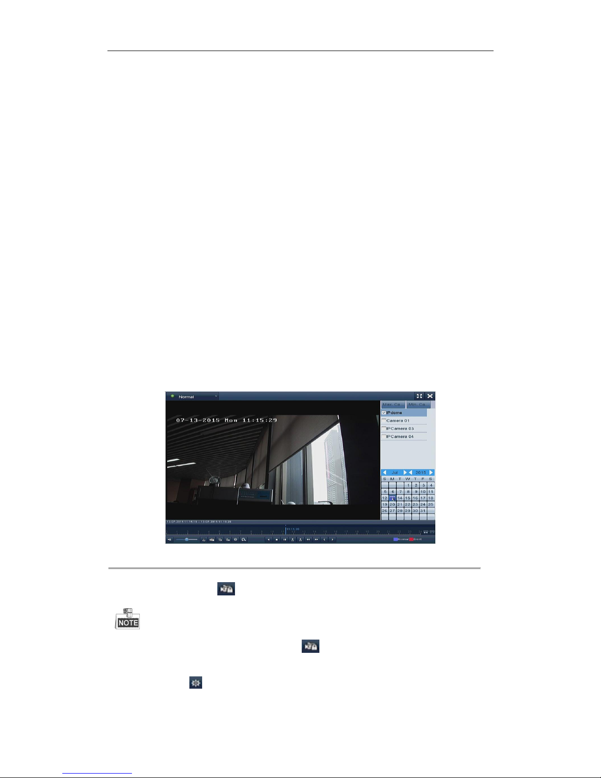
User Manual of Network Video Recorder
68
3) Select Mode from the dropdown list.
There are three different modes for the date format to configure holiday schedule.
4) Set the start and end date.
5) Click Apply to save settings.
6) Click OK to exit the Edit interface.
3. Enter Record Schedule settings interface to edit the holiday recording schedule. See Chapter 5.2 Configuring
Recording Schedule.
5.8 Files Protection
Purpose:
You can lock the recording files or set the HDD property to Read-only to protect the record files from being
overwritten.
5.8.1 Locking the Recording Files
Lock File when Playback
Steps:
1. Enter Playback interface.
Menu> Playback
2. Check the checkbox of channel(s) in the channel list and then double-click to select a date on the calendar.
Figure 5. 21 Normal Playback
3. During playback, click the button to lock the current recording file.
In the multi-channel playback mde, clicking the button will lock all the record files related to the
playback channels.
4. You can click the button to pop up the file management interface. Click the Locked File tab to check
and export the locked files.
Page 70
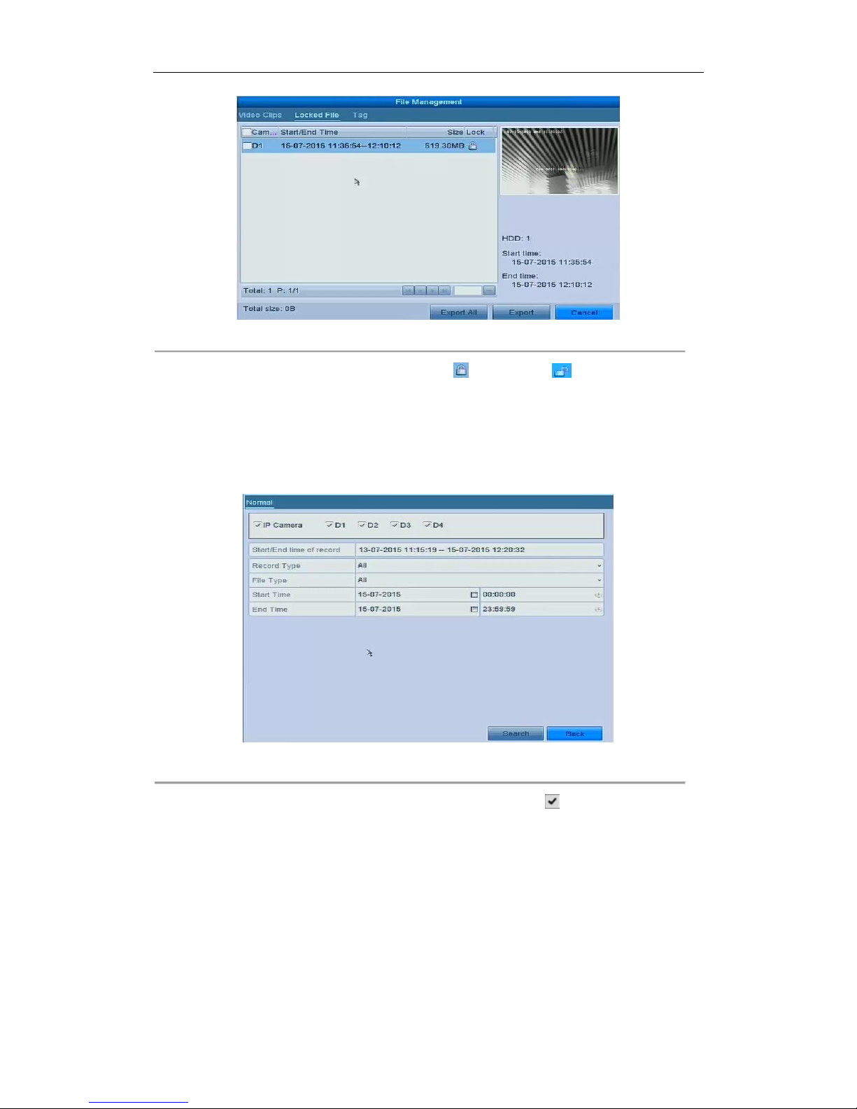
User Manual of Network Video Recorder
69
Figure 5. 22 Locked File Management
In the File Management interface, you can also click to change it to to unlock the file and the
file is not protected.
Lock File when Export
Steps:
1. Enter Export setting interface.
Menu > Export
Figure 5. 23 Export
2. Select the channels you want to investigate by checking the checkbox to .
3. Configure the record type, file type start/end time.
4. Click Search to show the results.
Page 71
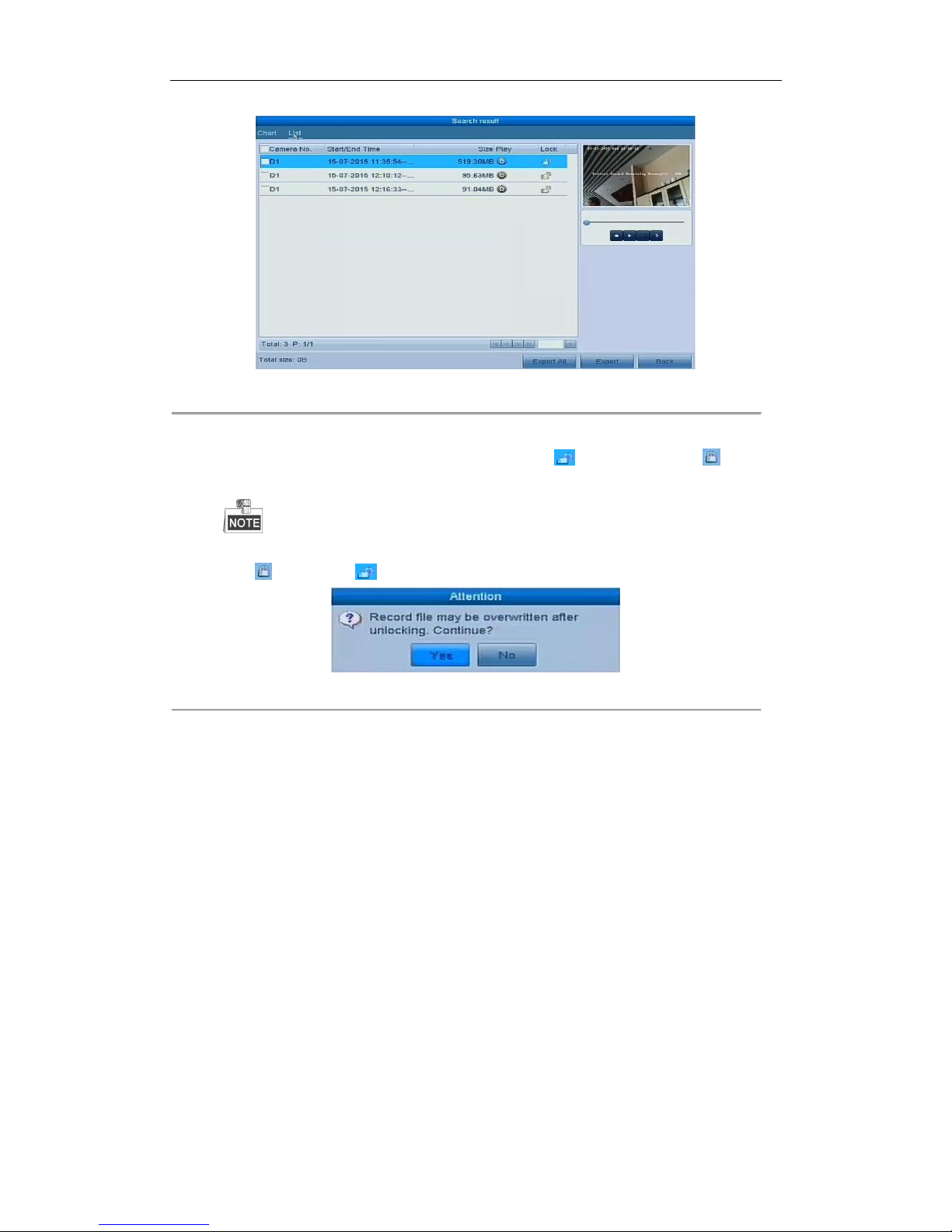
User Manual of Network Video Recorder
70
Figure 5. 24 Export- Search Result
5. Protect the record files.
1) Find the record files you want to protect, and then click the icon which will turn to , indicating
that the file is locked.
The record files of which the recording is still not completed cannot be locked.
2) Click to change it to to unlock the file and the file is not protected.
Figure 5. 25 Unlocking Attention
Page 72

User Manual of Network Video Recorder
71
Chapter 6 Playback
Page 73

User Manual of Network Video Recorder
72
6.1 Playing Back Record Files
6.1.1 Instant Playback
Purpose:
Play back the recorded video files of a specific channel in the live view mode. Channel switch is supported.
Instant playback by channel
Step:
Choose a channel in live view mode and click the button in the quick setting toolbar.
In the instant playback mode, only record files recorded during the last five minutes on this channel will be
played back.
Figure 6. 1 Instant Playback Interface
6.1.2 Playing Back by Normal Search
Playback by Channel
1. Enter the Playback interface.
Mouse: right click a channel in live view mode and select Playback from the menu, as shown in Figure 6. 2.
Page 74
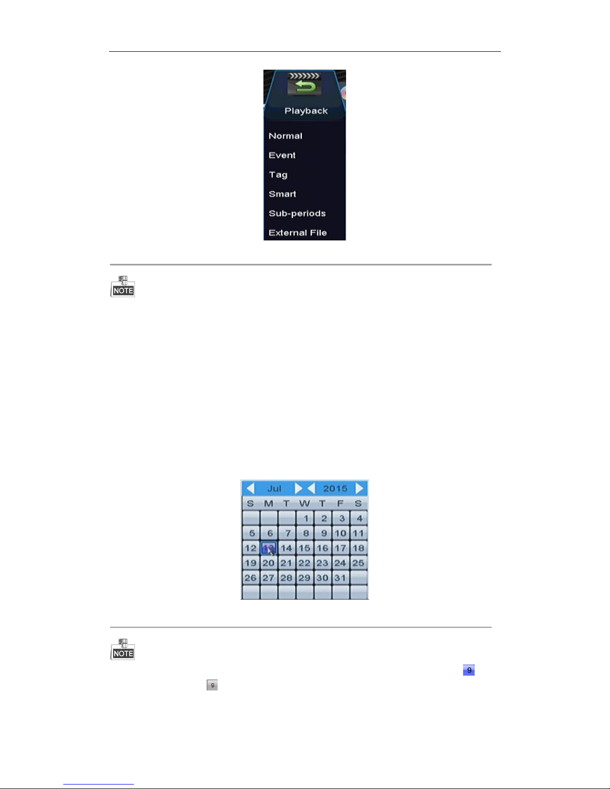
User Manual of Network Video Recorder
73
Figure 6. 2 Right-click Menu under Live View
Pressing numerical buttons will switch playback to the corresponding channels during playback process.
Playback by Time
Purpose:
Play back video files recorded in specified time duration. Multi-channel simultaneous playback and channel
switch are supported.
Steps:
1. Enter playback interface.
Menu > Playback
2. Check the checkbox of channel(s) in the channel list and then double-click to select a date on the calendar.
Figure 6. 3 Playback Calendar
If there are record files for that camera in that day, in the calendar, the icon for that day is displayed as .
Otherwise it is displayed as
Page 75
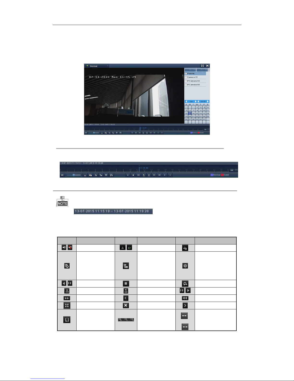
User Manual of Network Video Recorder
74
Playback Interface
You can use the toolbar in the bottom part of Playback interface to control playing progress.
Figure 6. 4 Playback Interface
Click the channel(s) to execute simultaneous playback of multiple channels.
Figure 6. 5 Toolbar of Playback
The indicates the start/end time of the record.
Playback progress bar: use the mouse to click any point of the progress bar or drag the progress bar to
locate specific frames.
Table 6. 1 Detailed Explanation of Playback Toolbar
Button
Operation
Button
Operation
Button
Operation
/
Audio on/ Mute
/
Start/Stop clipping
Lock File
Add default tag
Add customized tag
File management for
video clips, captured
pictures, locked files
and tags
/
Reverse play/ Pause
Stop
Digital Zoom
30s forward
30s reverse
/
Pause / Play
Fast forward
Previous day
Slow forward
Full Screen
Exit Next day
Save the clips
Process bar
/
Scaling up/down the
time line
Page 76
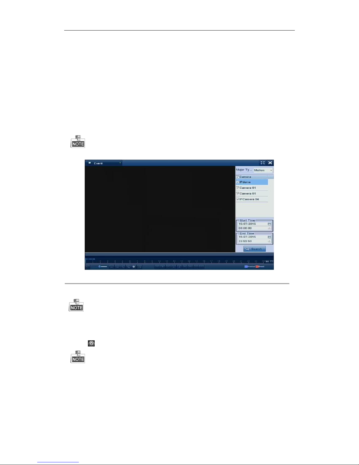
User Manual of Network Video Recorder
75
6.1.3 Playing Back by Event Search
Purpose:
Play back record files on one or several channels searched out by event type (e.g., alarm input, motion detection
and VCA).
Steps:
1. Enter the Playback interface.
Menu > Playback
2. Select the Event in the drop-down list on the top-left side.
3. Select Alarm Input, Motion or VCA as the event type.
Here we take playback by VCA as the example.
Figure 6. 6 Motion Search Interface
4. Select the minor type of VCA from the drop-down list.
For configuring the VCA recording, please refer to Chapter 5.5 Configuring VCA Event Recording.
5. Select the camera (s) for searching, and set the Start time and End time.
6. Click Search button to get the search result information. You may refer to the right-side bar for the result.
7. Click button to play back the file.
Pre-play and post-play can be configured.
8. Playback interface.
The toolbar in the bottom part of Playback interface can be used to control playing process.
Page 77
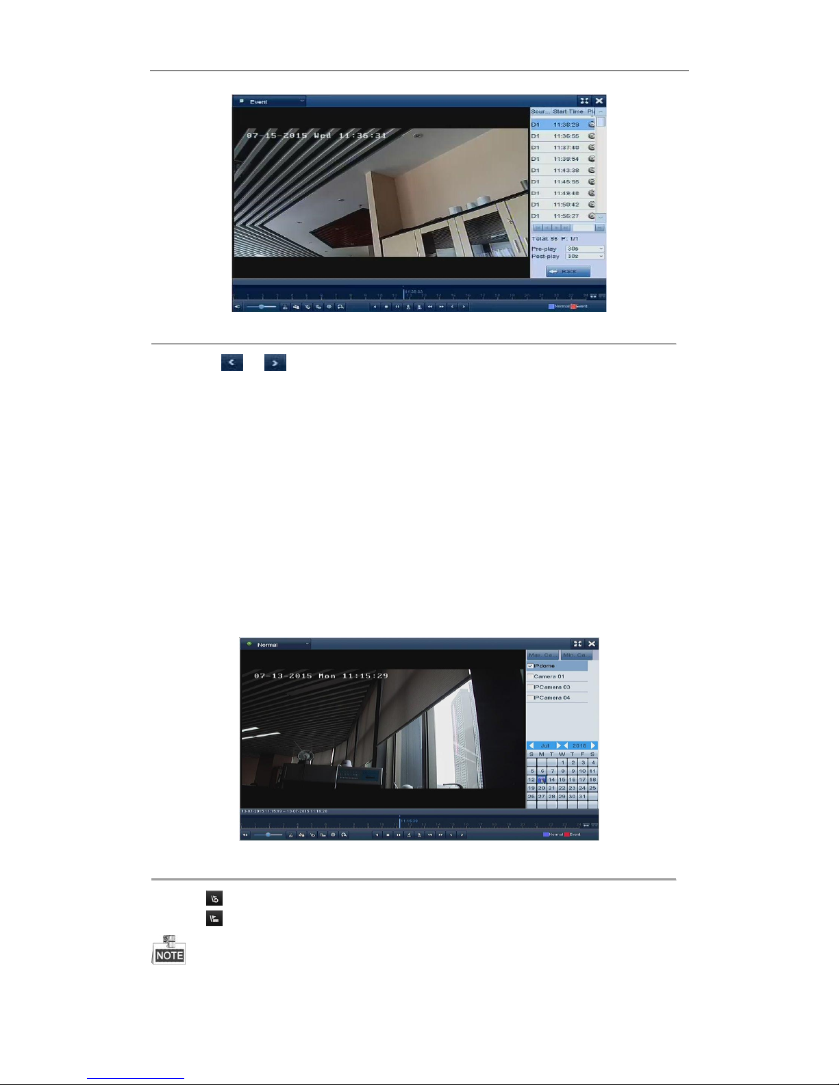
User Manual of Network Video Recorder
76
Figure 6. 7 Interface of Playback by Event
You can click or button to select the previous or next event. Please refer to Table 6. 1 for the
description of buttons on the toolbar.
6.1.4 Playing Back by Tag
Purpose:
Video tag allows you to record related information like people and location of a certain time point during
playback. You can use video tag(s) to search for record files and position time point.
Before playing back by tag:
1. Enter Playback interface.
Menu > Playback
2. Search and play back the record file(s). Refer to Chapter 6.1 for the detailed information about searching
and playback of the record files.
Figure 6. 8 Interface of Playback by Time
Click button to add default tag.
Click button to add customized tag and input tag name.
Max. 64 tags can be added to a single video file.
Page 78
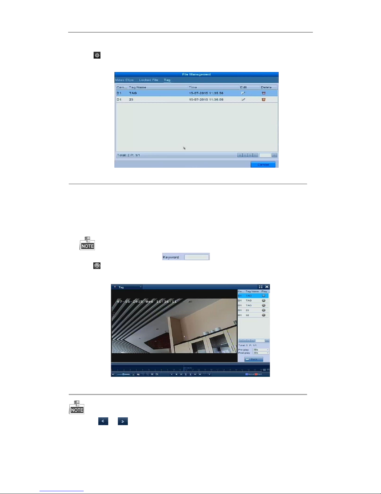
User Manual of Network Video Recorder
77
3. Tag management.
Click button to enter the File Management interface and click Tag to manage the tags. You can check,
edit and delete tag(s).
Figure 6. 9 Tag Management Interface
Playing back by Tag
Steps:
1. Select the Tag from the drop-down list in the Playback interface.
2. Choose channels, edit start time and end time, and then click Search to enter Search Result interface.
You can enter keyword in the textbox to search the tag on your command.
3. Click button to play back the selected tag file.
You can click the Back button to back to the search interface.
Figure 6. 10 Interface of Playback by Tag
Pre-play and post-play can be configured.
You can click or button to select the previous or next tag. Please refer to Table 6. 1 for the description
of buttons on the toolbar.
Page 79
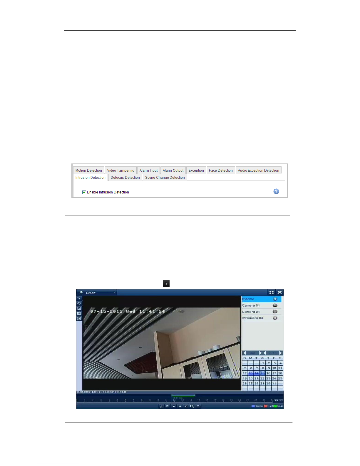
User Manual of Network Video Recorder
78
6.1.5 Playing back by Smart Playback
Purpose:
The smart playback function provides an easy way to get through the less effective information. When you select
the smart playback mode, the system will analyze the video containing the motion or VCA information, mark it
with green color and play it in the normal speed while the video without motion will be played in the 16-time
speed. The smart playback rules and areas are configurable.
Before you start:
To get the smart search result, the corresponding event type must be enabled and configured on the IP camera.
Here we take the intrusion detection as an example.
1. Log in the IP camera by the web browser, and enable the intrusion detection by checking the checkbox of it.
You may enter the motion detection configuration interface by Configuration > Advanced Configuration >
Events > Intrusion Detection.
Figure 6. 11 Setting Intrusion Detection on IP Camera
2. Configure the required parameters of intrusion detection, including area, arming schedule and linkage
methods. Refer to the user manual of smart IP camera for detailed instructions.
Steps:
1. Enter Playback interface.
Menu > Playback
2. Select the Smart in the drop-down list on the top-left side.
3. Select a camera in the camera list.
4. Select a date in the calendar and click the button on the left toolbar to play the video file.
Figure 6. 12 Smart Playback Interface
Page 80
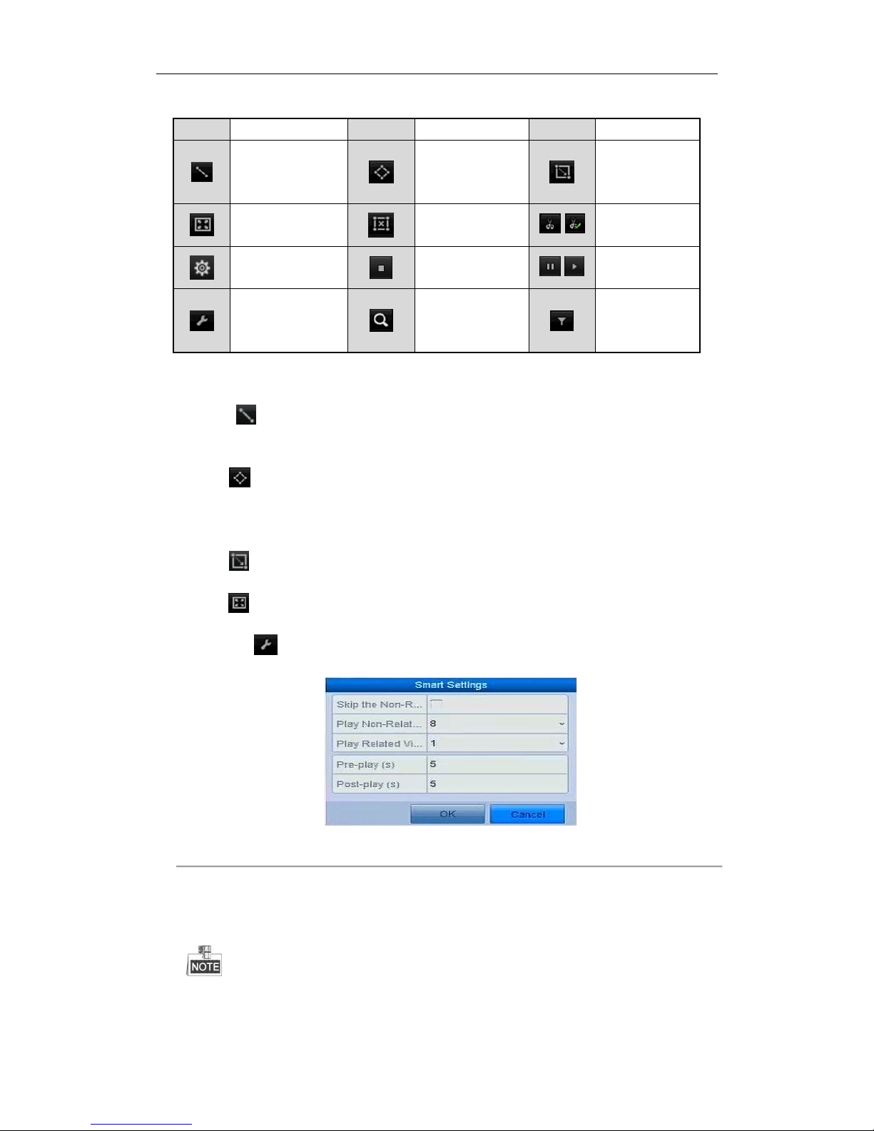
User Manual of Network Video Recorder
79
Table 6. 2 Detailed Explanation of Smart Playback Toolbar
Button
Operation
Button
Operation
Button
Operation
Draw line for the line
crossing detection
Draw quadrilateral
for the intrusion
detection
Draw rectangle
for the intrusion
detection
Set full screen for
motion detection
Clear all
/
Start/Stop
clipping
File management for
video clips
Stop playing
/
Pause playing /
Play
Smart settings
Search matched
video files
Filter video files
by setting the
target characters
5. Set the rules and areas for smart search of VCA event or motion event.
Line Crossing Detection
Select the button , and click on the image to specify the start point and end point of the line.
Intrusion Detection
Click the button, and specify 4 points to set a quadrilateral region for intrusion detection. Only one
region can be set.
Motion Detection
Click the button and then click and draw the mouse to set the detection area manually. You can also
click the button to set the full screen as the detection area.
6. You can click to configure the smart settings.
Figure 6. 13 Smart Settings
Skip the Non-Related Video: The non-related video will not be played if this function is enabled.
Play Non-Related Video at: Set the speed to play the non-related video. Max./8/4/1 are selectable.
Play Related Video at: Set the speed to play the related video. Max./8/4/1 are selectable.
Pre-play and post-play is not available for the motion event type.
Page 81
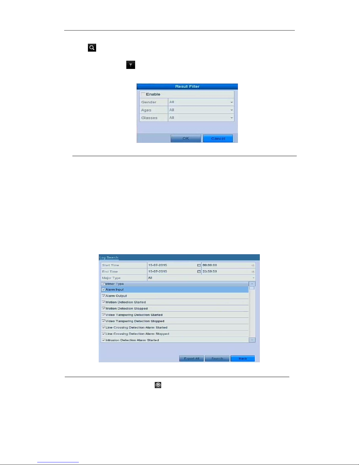
User Manual of Network Video Recorder
80
7. Click to search and play the matched video files.
8. (Optional) You can click to filter the searched video files by setting the target characters, including the
gender and age of the human and whether he/she wears glasses.
Figure 6. 14 Set Result Filter
6.1.6 Playing Back by System Logs
Purpose:
Play back record file(s) associated with channels after searching system logs.
Steps:
1. Enter Log Information interface.
Menu > Maintenance > Log Information
2. Click Log Search tab to enter Playback by System Logs.
Set search time and type and click Search button.
Figure 6. 15 System Log Search Interface
3. Choose a log with record file and click button to enter Playback interface.
Page 82
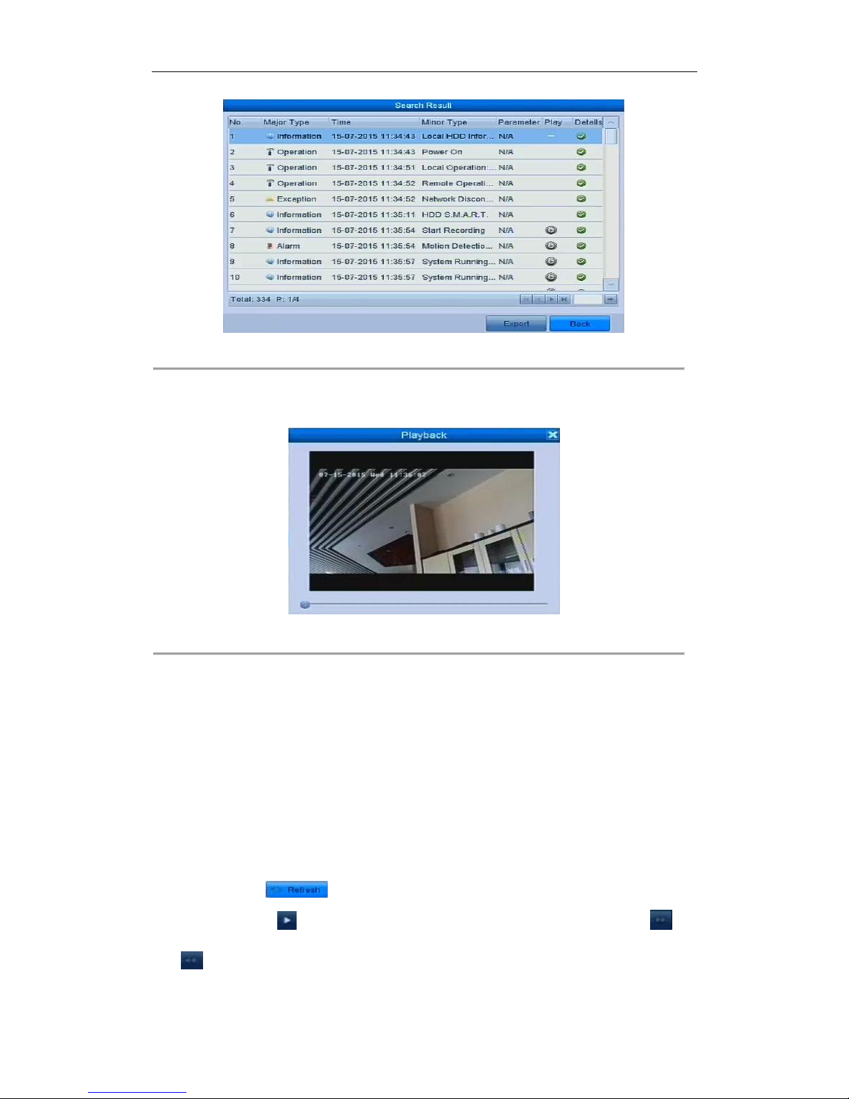
User Manual of Network Video Recorder
81
Figure 6. 16 Result of System Log Search
4. Playback interface.
The toolbar in the bottom part of Playback interface can be used to control playing process.
Figure 6. 17 Interface of Playback by Log
6.1.7 Playing Back External File
Purpose:
Perform the following steps to look up and play back files in the external devices.
Steps:
1. Enter Tag Search interface.
Menu > Playback
2. Select the External File in the drop-down list on the top-left side.
The files are listed in the right-side list.
You can click the button to refresh the file list.
3. Select and click the button to play back it. And you can adjust the playback speed by clicking and
.
Page 83
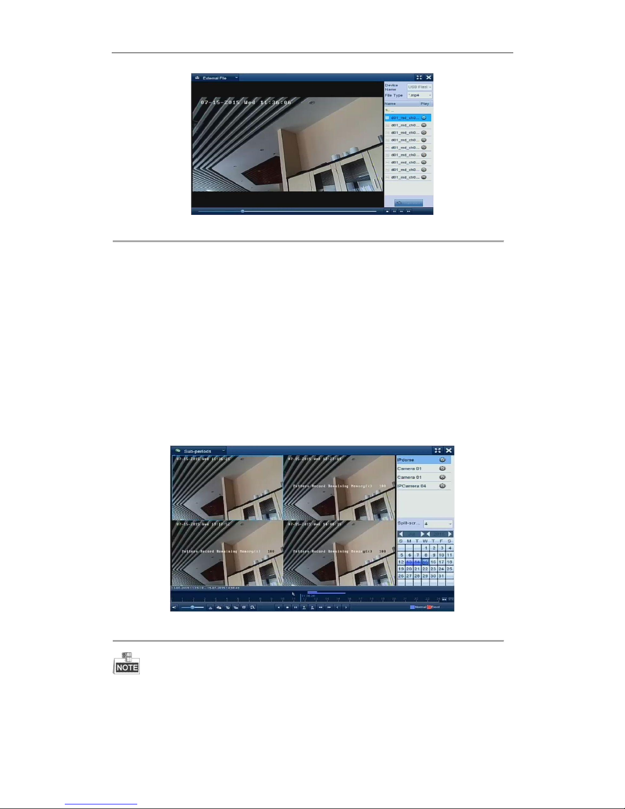
User Manual of Network Video Recorder
82
Figure 6. 18 Interface of External File Playback
6.1.8 Playing Back by Sub-periods
Purpose:
The video files can be played in multiple sub-periods simultaneously on the screens.
Steps:
1. Enter Playback interface.
Menu > Playback
2. Select Sub-periods from the drop-down list in the upper-left corner of the page to enter the Sub-periods
Playback interface.
3. Select a date and start playing the video file.
4. Select the Split-screen Number from the dropdown list. Up to 16 screens are configurable.
Figure 6. 19 Interface of Sub-periods Playback
According to the defined number of split-screens, the video files on the selected date can be divided into average
segments for playback. E.g., if there are video files existing between 16:00 and 22:00, and the 6-screen display
mode is selected, then it can play the video files for 1 hour on each screen simultaneously.
Page 84

User Manual of Network Video Recorder
83
Chapter 7 Backup
Page 85
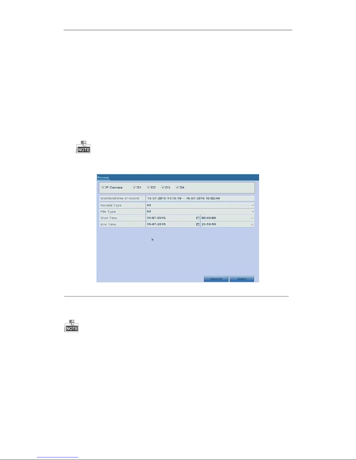
User Manual of Network Video Recorder
84
7.1 Backing up Record Files
7.1.1 Quick Export
Purpose:
Export record files to backup device(s) quickly.
Steps:
1. Enter Video Export interface.
Menu > Export > Normal
Choose the channel(s) you want to back up and click Quick Export button.
The time duration of record files on a specified channel cannot exceed one day. Otherwise, the message
box “Max. 24 hours are allowed for quick export.” will pop up.
Figure 7. 1 Quick Export Interface
2. Select the format of the log files to be exported. Up to 9 formats are selectable.
3. Click the Export to start exporting.
Here we use USB Flash Drive and please refer to the next section Normal Backup for more backup devices
supported by the NVR.
Page 86
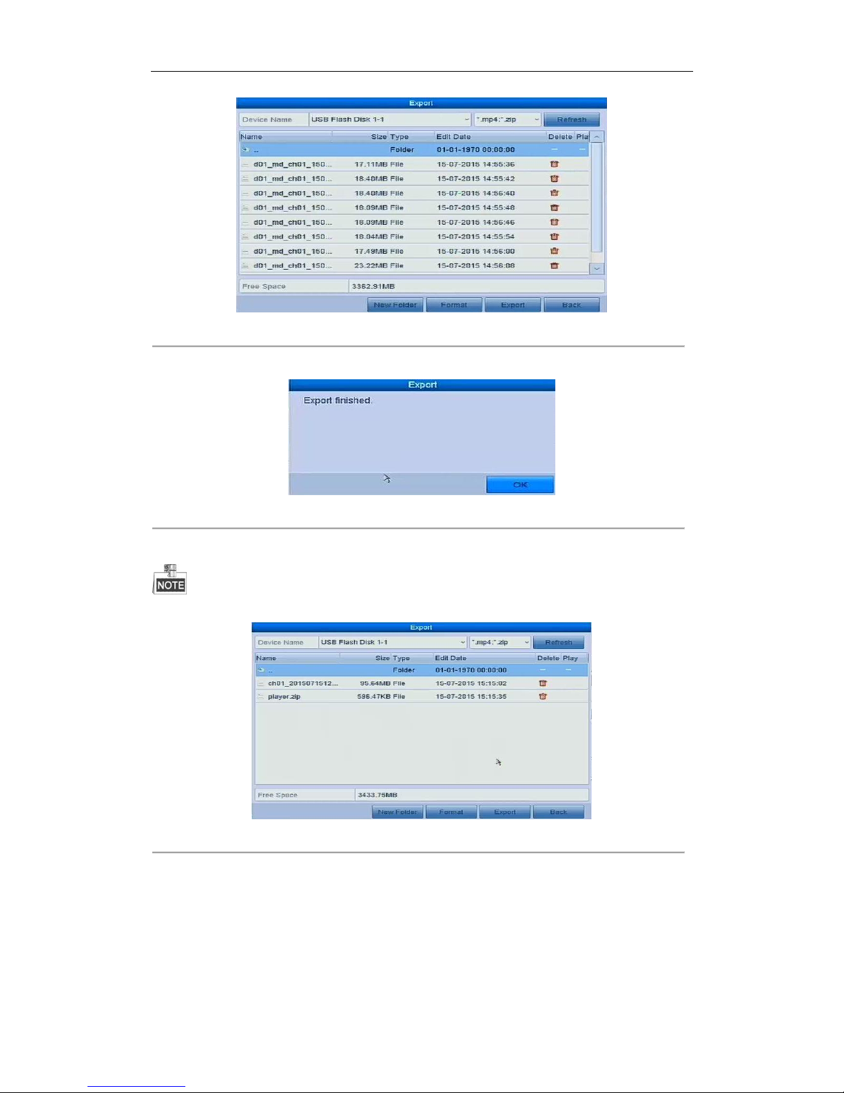
User Manual of Network Video Recorder
85
Figure 7. 2 Quick Export using USB1-1
Stay in the Exporting interface until all record files are exported.
Figure 7. 3 Export Finished
4. Check backup result.
The Player player.exe will be exported automatically during record file export.
Figure 7. 4 Checkup of Quick Export Result Using USB1-1
7.1.2 Backing up by Normal Video Search
Purpose:
The record files can be backup to various devices, such as USB devices (USB flash drives, USB HDDs, USB writer),
SATA writer and e-SATA HDD.
Page 87
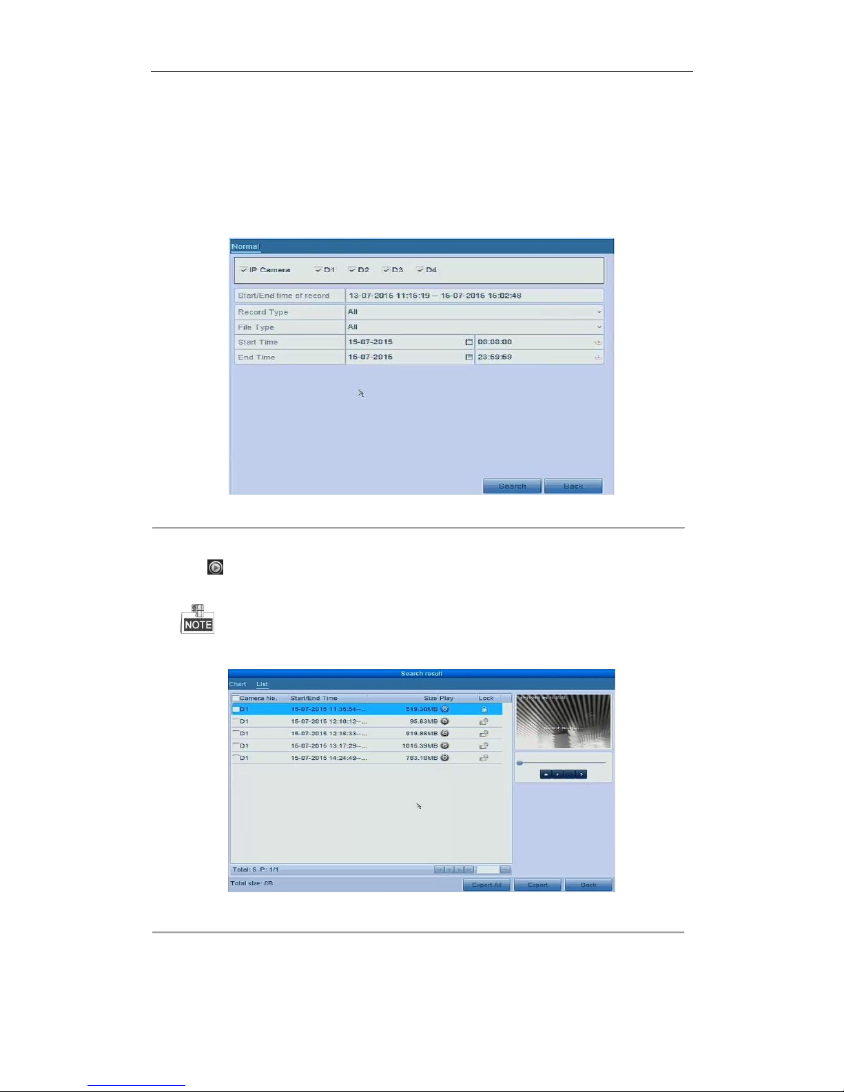
User Manual of Network Video Recorder
86
Backup using USB flash drives and USB HDDs
Steps:
1. Enter Export interface.
Menu>Export>Normal
2. Select the cameras to search.
3. Set search condition and click Search button to enter the search result interface. The matched video files
are displayed in Chart or List display mode.
Figure 7. 5 Normal Video Search for Backup
4. Select video files or pictures from the Chart or List to export.
Click to play the record file if you want to check it.
Check the checkbox before the record files you want to back up.
The size of the currently selected files is displayed in the lower-left corner of the window.
Figure 7. 6 Result of Normal Video Search for Backup
5. Export the video files or picture files.
Click Export All button to export all the files.
Page 88
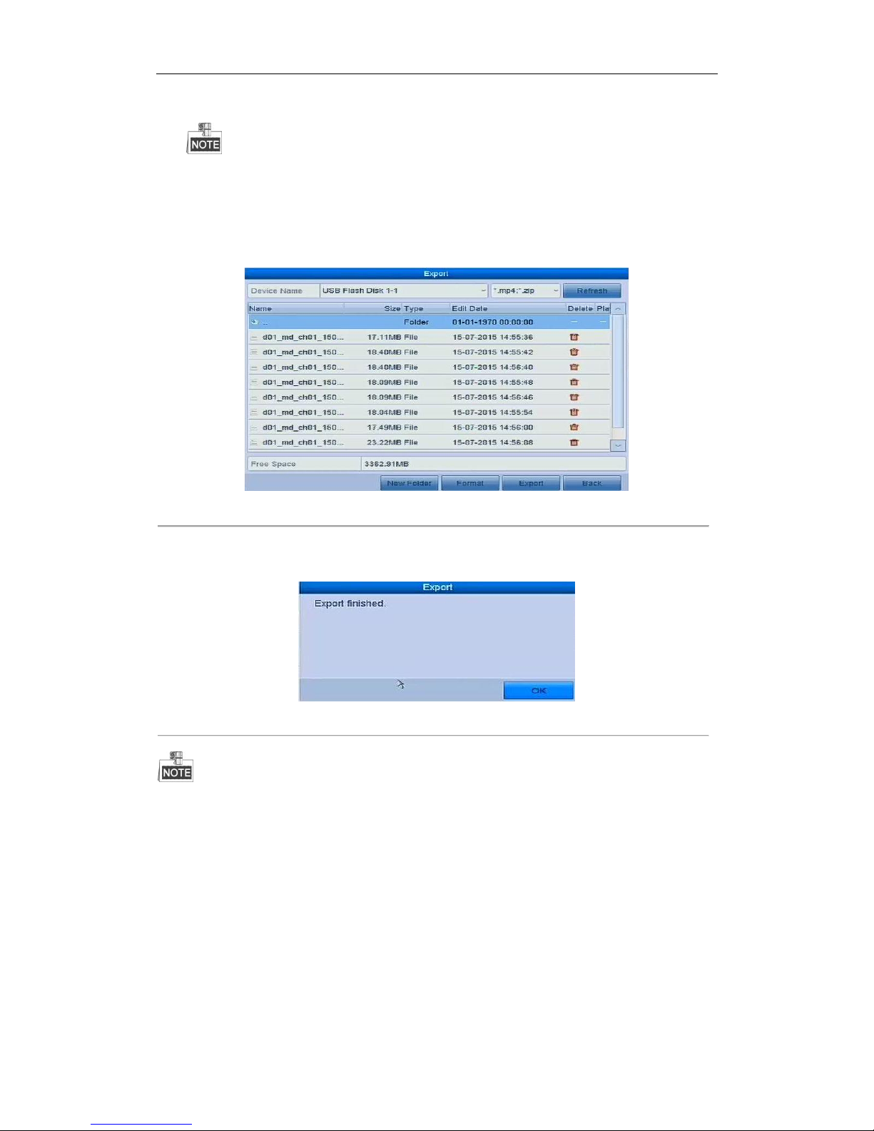
User Manual of Network Video Recorder
87
Or you can select recording files you want to back up, and click Export button to enter Export interface.
If the inserted USB device is not recognized:
• Click the Refresh button.
• Reconnect device.
• Check for compatibility from vendor.
You can also format USB flash drives or USB HDDs via the device.
Figure 7. 7 Export by Normal Video Search using USB Flash Drive
Stay in the Exporting interface until all record files are exported with pop-up message box “Export
finished”.
Figure 7. 8 Export Finished
The backup of video files using USB writer or SATA writer has the same operating instructions. Please refer to
steps described above.
7.1.3 Backing up by Event Search
Purpose:
Back up event-related record files using USB devices (USB flash drives, USB HDDs, USB writer), SATA writer or
eSATA HDD. Quick Backup and Normal Backup are supported.
Steps:
1. Enter Export interface.
Menu > Export > Event
Page 89
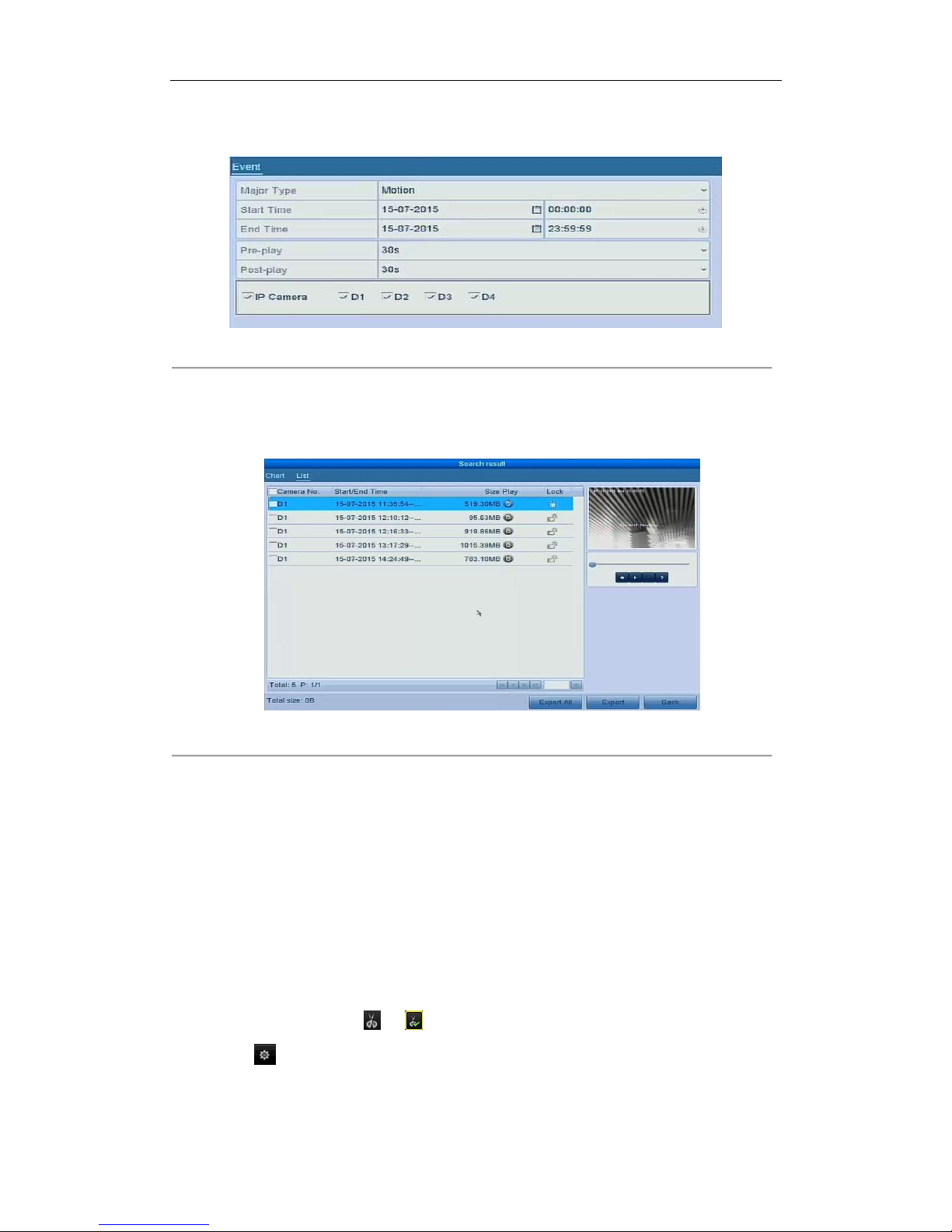
User Manual of Network Video Recorder
88
2. Select the cameras to search.
3. Select the event type to alarm input, motion or VCA.
Figure 7. 9 Event Search for Backup
4. Set search condition and click Search button to enter the search result interface. The matched video files
are displayed in Chart or List display mode.
5. Select video files from the Chart or List interface to export.
Figure 7. 10 Result of Event Search
6. Export the video files. Please refer to step5 of Chapter 7.1.2 Backing up by Normal Video Search for details.
7.1.4 Backing up Video Clips
Purpose:
You may also select video clips in playback mode to export directly during Playback, using USB devices (USB flash
drives, USB HDDs, USB writer), SATA writer or eSATA HDD.
Steps:
1. Enter Playback interface.
Please refer to Chapter 6.1 Playing Back Record Files.
2. During playback, use buttons or in the playback toolbar to start or stop clipping record file(s).
3. Click the to enter the file management interface.
Page 90
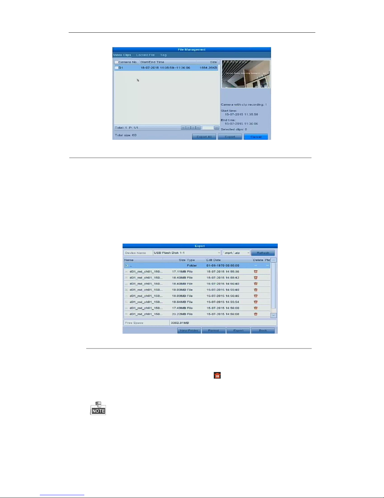
User Manual of Network Video Recorder
89
Figure 7. 11 Video Clips Export Interface
7. Export the video clips in playback. Please refer to step5 of Chapter 7.1.2 Backing up by Normal Video Search
for details.
7.2 Managing Backup Devices
Management of USB flash drives and USB HDDs
Steps:
1. Enter the Export interface.
Figure 7. 12 Storage Device Management
2. Backup device management.
Click New Folder button if you want to create a new folder in the backup device.
Select a record file or folder in the backup device and click button if you want to delete it.
Click Erase button if you want to erase the files from a re-writable CD/DVD.
Click Format button to format the backup device.
If the inserted storage device is not recognized:
• Click the Refresh button.
• Reconnect device.
• Check for compatibility from vendor.
Page 91

User Manual of Network Video Recorder
90
Chapter 8 Alarm Settings
Page 92
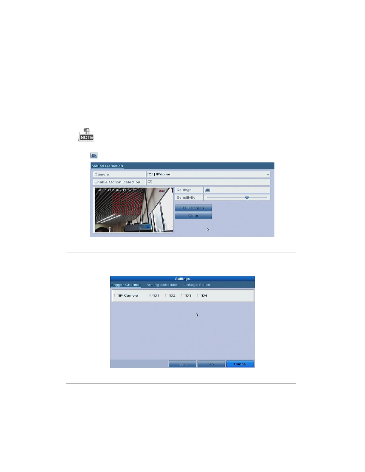
User Manual of Network Video Recorder
91
8.1 Setting Motion Detection Alarm
Steps:
1. Enter Motion Detection interface of Camera Management and choose a camera you want to set up motion
detection.
Menu > Camera > Motion
2. Set up detection area and sensitivity.
Tick Enable Motion Detection, and use the mouse to draw detection area(s) and drag the sensitivity bar to
set sensitivity.
By default, the motion detection is enabled and configured in full screen.
Click button and set alarm response actions.
Figure 8. 1 Motion Detection Setup Interface
3. Click Trigger Channel tab and select one or more channels which will start to record or become full-screen
monitoring when motion alarm is triggered, and click Apply to save the settings.
Figure 8. 2 Set Trigger Camera of Motion Detection
4. Set up arming schedule of the channel.
1) Select Arming Schedule tab to set the arming schedule of handling actions for the motion detection.
2) Choose one day of a week and up to eight time periods can be set within each day.
3) Click Apply to save the settings
Page 93
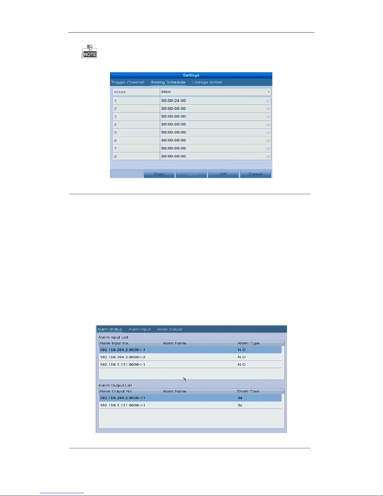
User Manual of Network Video Recorder
92
Time periods shall not be repeated or overlapped.
Figure 8. 3 Set Arming Schedule of Motion Detection
5. Click Handling tab to set up alarm response actions of motion alarm (please refer to Chapter 8.6 Setting
Alarm Response Actions).
6. If you want to set motion detection for another channel, repeat the above steps or just click Copy in the
Motion Detection interface to copy the above settings to it.
8.2 Setting Sensor Alarms
Purpose:
Set the handling action of an external sensor alarm.
Steps:
1. Enter Alarm Settings of System Configuration and select an alarm input.
Menu> Configuration> Alarm
Select Alarm Input tab to enter Alarm Input Settings interface.
Figure 8. 4 Alarm Status Interface of System Configuration
Page 94
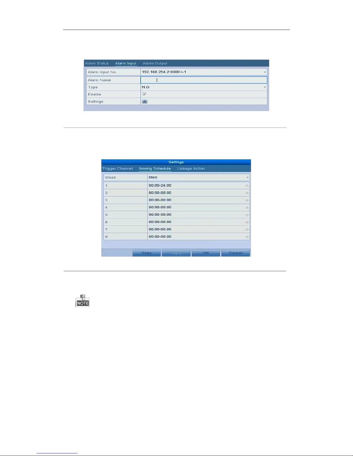
User Manual of Network Video Recorder
93
2. Set up the handling action of the selected alarm input.
Check the Enable checkbox and click Settings button to set up its alarm response actions.
Figure 8. 5 Alarm Input Setup Interface
3. Select Trigger Channel tab and select one or more channels which will start to record or become full-screen
monitoring when an external alarm is input, and click Apply to save the settings.
4. Select Arming Schedule tab to set the arming schedule of handling actions.
Figure 8. 6 Set Arming Schedule of Alarm Input
Choose one day of a week and Max. eight time periods can be set within each day, and click Apply to save
the settings.
Time periods shall not be repeated or overlapped.
Repeat the above steps to set up arming schedule of other days of a week. You can also use Copy button
to copy an arming schedule to other days.
5. Select Linkage Action tab to set up alarm response actions of the alarm input (please refer to Chapter 8.6
Setting Alarm Response Actions).
8.3 Detecting Video Loss Alarm
Purpose:
Detect video loss of a channel and take alarm response action(s).
Steps:
1. Enter Video Loss interface of Camera Management and select a channel you want to detect.
Page 95
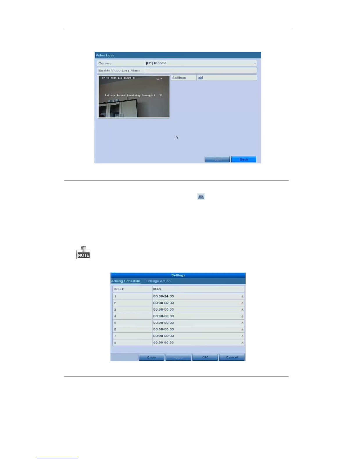
User Manual of Network Video Recorder
94
Menu > Camera > Video Loss
Figure 8. 7 Video Loss Setup Interface
2. Set up handling action of video loss.
Check the checkbox of “Enable Video Loss Alarm”, and click button to set up handling action of video
loss.
3. Set up arming schedule of the handling actions.
1) Select Arming Schedule tab to set the channel’s arming schedule.
2) Choose one day of a week and up to eight time periods can be set within each day.
3) Click Apply button to save the settings.
Time periods shall not be repeated or overlapped.
Figure 8. 8 Set Arming Schedule of Video Loss
4. Select Linkage Action tab to set up alarm response action of video loss (please refer to Chapter 8.6 Setting
Alarm Response Actions).
5. Click the OK button to complete the video loss settings of the channel.
Page 96
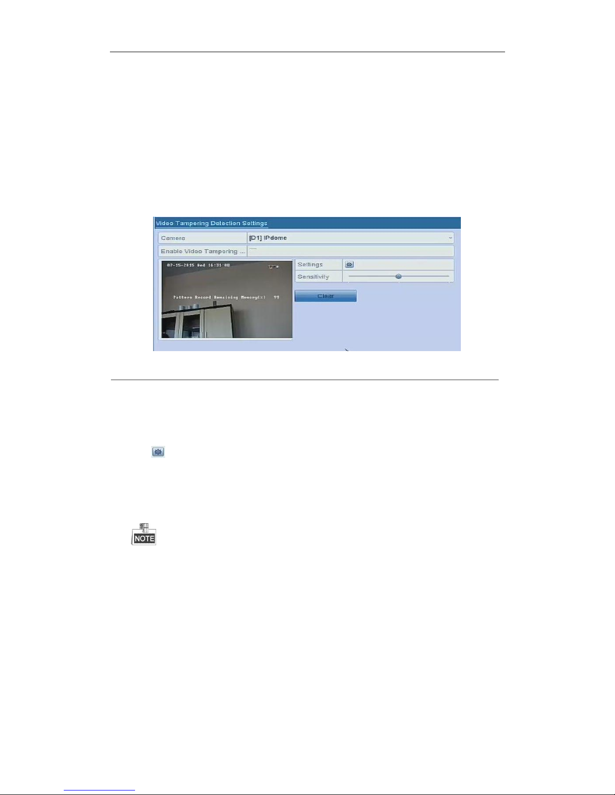
User Manual of Network Video Recorder
95
8.4 Detecting Video Tampering Alarm
Purpose:
Trigger alarm when the lens is covered and take alarm response action(s).
Steps:
1. Enter Video Tampering interface of Camera Management and select a channel you want to detect video
tampering.
Menu> Camera> Video Tampering
Figure 8. 9 Video Tampering Setup Interface
2. Set the video tampering handling action of the channel.
Check the checkbox of Enable Video Tampering Detection.
Drag the sensitivity bar to set a proper sensitivity level. Use the mouse to draw an area you want to detect
video tampering.
Click button to set up handling action of video tampering.
3. Set arming schedule and alarm response actions of the channel.
1) Click Arming Schedule tab to set the arming schedule of handling actions.
2) Choose one day of a week and max. eight time periods can be set within each day.
3) Click Apply button to save the settings.
Time periods shall not be repeated or overlapped.
Page 97
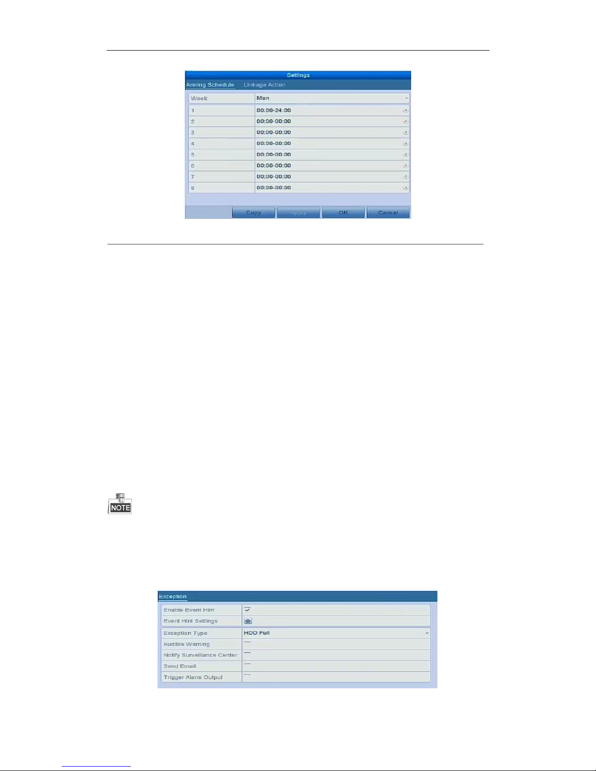
User Manual of Network Video Recorder
96
Figure 8. 10 Set Arming Schedule of Video Tampering
4. Select Linkage Action tab to set up alarm response actions of video tampering alarm (please refer to
Chapter 8.6 Setting Alarm Response Actions).
5. Click the OK button to complete the video tampering settings of the channel.
8.5 Handling Exceptions Alarm
Purpose:
Exception settings refer to the handling action of various exceptions, e.g.
• HDD Full: The HDD is full.
• HDD Error: Writing HDD error or unformatted HDD.
• Network Disconnected: Disconnected network cable.
• IP Conflicted: Duplicated IP address.
• Illegal Login: Incorrect user ID or password.
• Record Exception: No space for saving recorded files.
• PoE Power Overload: The power consumption of the connected cameras via the PoE interface exceeds the
maximum PoE power.
PoE Power Overload is only supported by the models with POE interface.
Steps:
Enter Exception interface of System Configuration and handle various exceptions.
Menu> Configuration> Exceptions
Please refer to Chapter 8.6 Setting Alarm Response Actions for detailed alarm response actions.
Figure 8. 11 Exceptions Setup Interface
Page 98
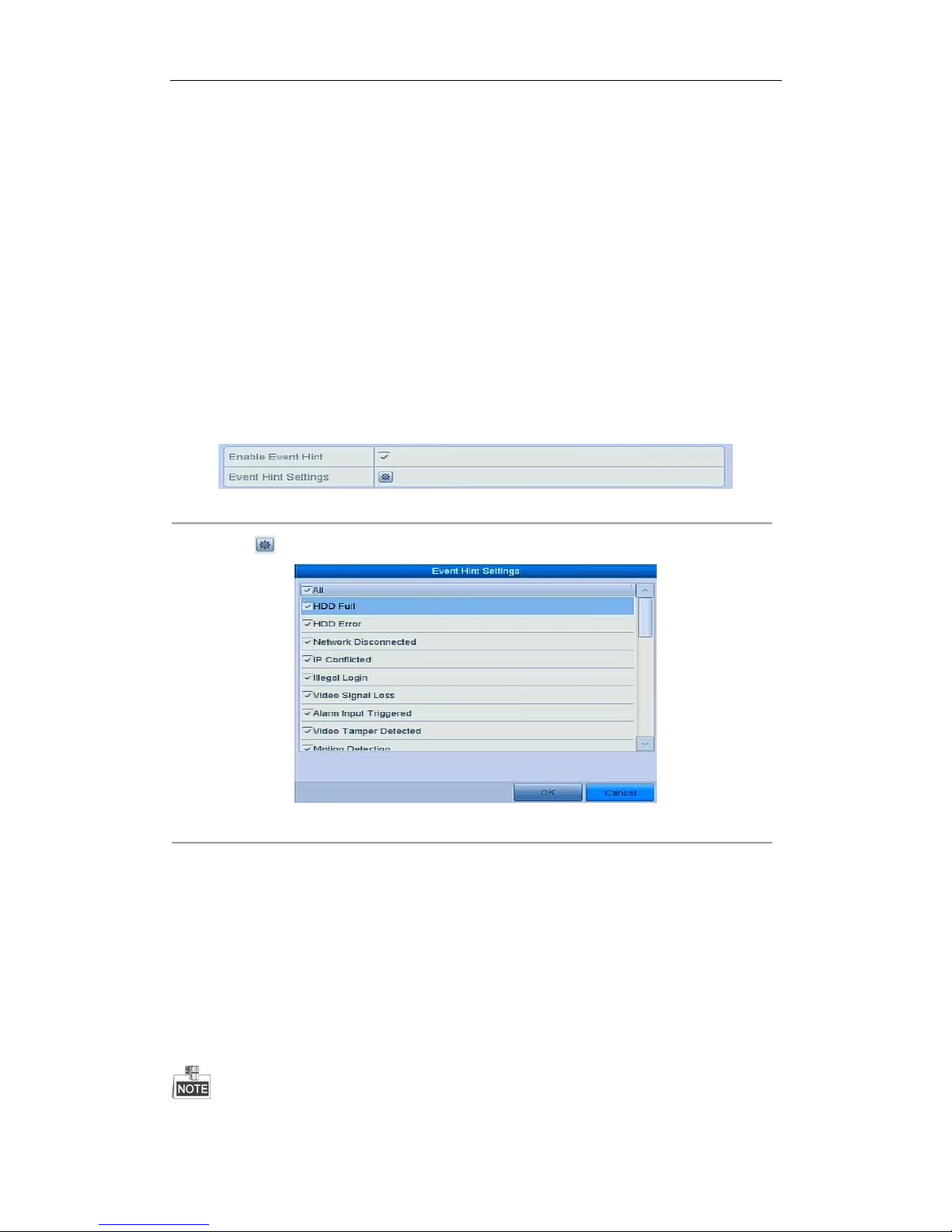
User Manual of Network Video Recorder
97
8.6 Setting Alarm Response Actions
Purpose:
Alarm response actions will be activated when an alarm or exception occurs, including Event Hint Display, Full
Screen Monitoring, Audible Warning (buzzer), Notify Surveillance Center, Upload Picture to FTP, Trigger Alarm
Output and Send Email.
Event Hint Display
When an event or exception happens, a hint can be displayed on the lower-left corner of live view image. And you
can click the hint icon to check the details. Besides, the event to be displayed is configurable.
Steps:
1. Enter the Exception settings interface.
Menu > Configuration > Exceptions
2. Check the checkbox of Enable Event Hint.
Figure 8. 12 Event Hint Settings Interface
3. Click the to set the type of event to be displayed on the image.
Figure 8. 13 Event Hint Settings Interface
4. Click the OK button to finish settings.
Full Screen Monitoring
When an alarm is triggered, the local monitor (VGA and HDMITM monitor) display in full screen the video image
from the alarming channel configured for full screen monitoring.
If alarms are triggered simultaneously in several channels, their full-screen images will be switched at an interval
of 10 seconds (default dwell time). A different dwell time can be set by going to Menu >Configuration>Live
View > Full Screen Monitoring Dwell Time.
Auto-switch will terminate once the alarm stops and you will be taken back to the Live View interface.
You must select during “Trigger Channel” settings the channel(s) you want to make full screen monitoring.
Page 99
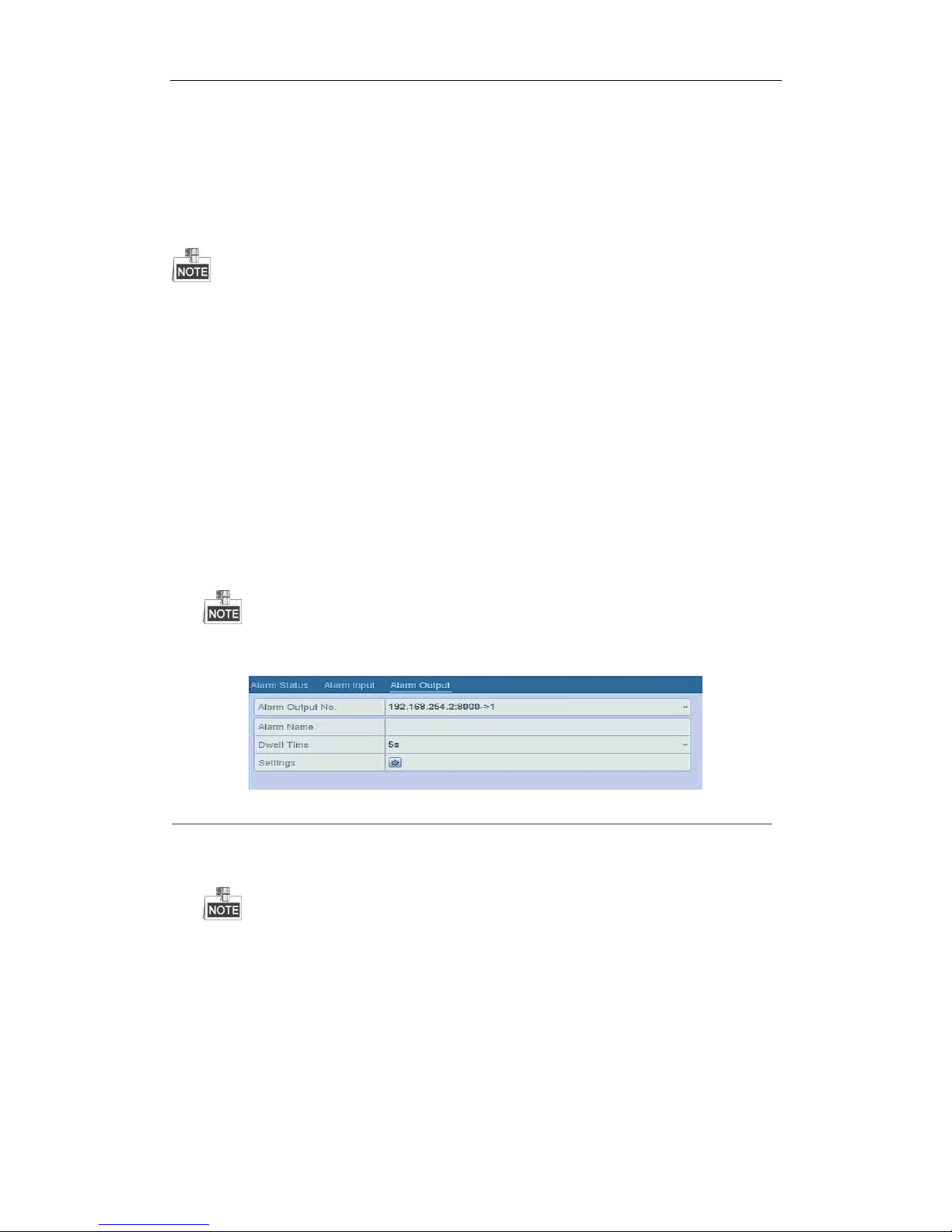
User Manual of Network Video Recorder
98
Audible Warning
Trigger an audible beep when an alarm is detected.
Notify Surveillance Center
Sends an exception or alarm signal to remote alarm host when an event occurs. The alarm host refers to the PC
installed with Remote Client.
The alarm signal will be transmitted automatically at detection mode when remote alarm host is configured.
Please refer to Chapter 10.2.5 Configuring Remote Alarm Host for details of alarm host configuration.
Email Linkage
Send an email with alarm information to a user or users when an alarm is detected.
Please refer to Chapter 10.2.9 for details of Email configuration.
Trigger Alarm Output
Trigger an alarm output when an alarm is triggered.
1. Enter Alarm Output interface.
Menu> Configuration> Alarm> Alarm Output
Select an alarm output and set alarm name and dwell time. Click Schedule button to set the arming
schedule of alarm output.
If “Manually Clear” is selected in the dropdown list of Dwell Time, you can clear it only by going to Menu>
Manual> Alarm.
Figure 8. 14 Alarm Output Setup Interface
2. Set up arming schedule of the alarm output.
Choose one day of a week and up to 8 time periods can be set within each day.
Time periods shall not be repeated or overlapped.
Page 100
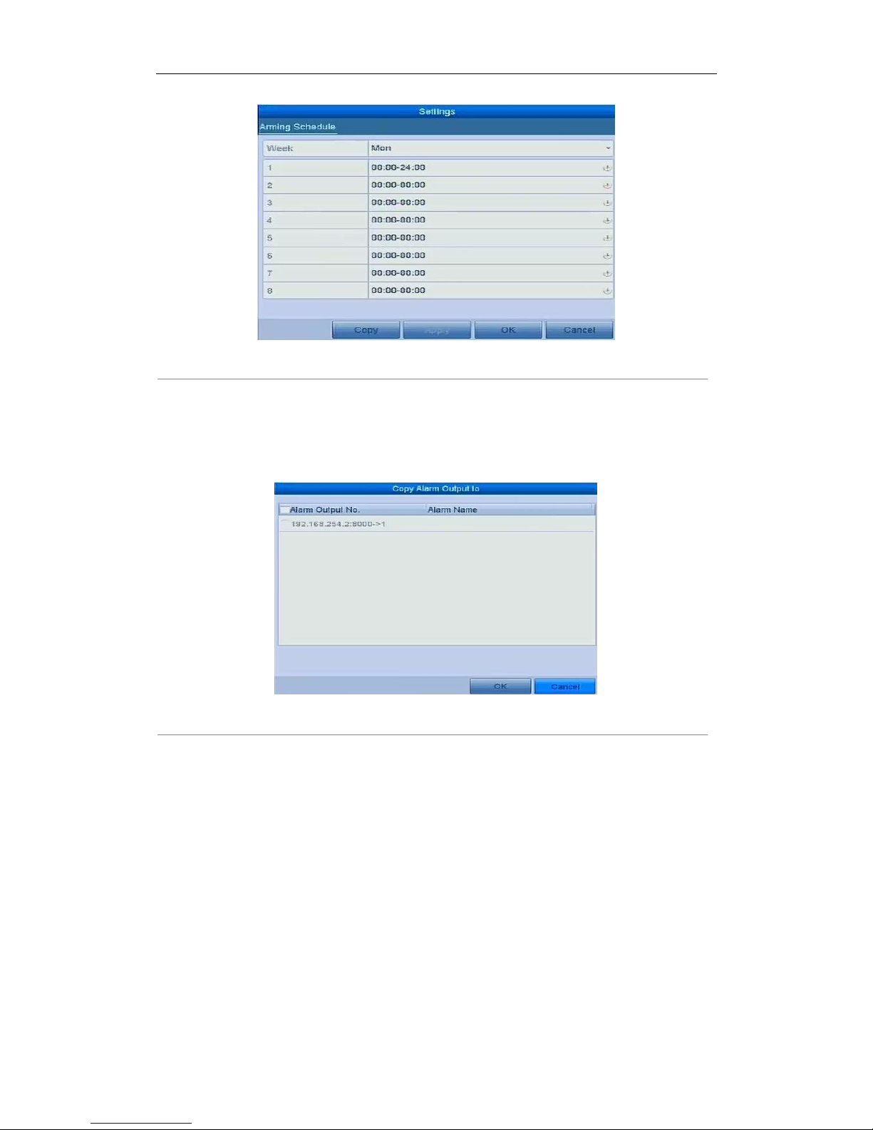
User Manual of Network Video Recorder
99
Figure 8. 15 Set Arming Schedule of Alarm Output
3. Repeat the above steps to set up arming schedule of other days of a week. You can also use Copy button to
copy an arming schedule to other days.
Click the OK button to complete the video tampering settings of the alarm output No.
4. You can also copy the above settings to another channel.
Figure 8. 16 Copy Settings of Alarm Output
8.7 Triggering or Clearing Alarm Output
Manually
Purpose:
Sensor alarm can be triggered or cleared manually. If “Manually Clear” is selected in the dropdown list of dwell
time of an alarm output, the alarm can be cleared only by clicking Clear button in the following interface.
Steps:
Select the alarm output you want to trigger or clear and make related operations.
Menu> Manual> Alarm
Click Trigger/Clear button if you want to trigger or clear an alarm output.
Click Trigger All button if you want to trigger all alarm outputs.
 Loading...