

Page 1
Single-Speed / Ramp-Hold Version
Sentry Xpress
Digital Temperature Controller
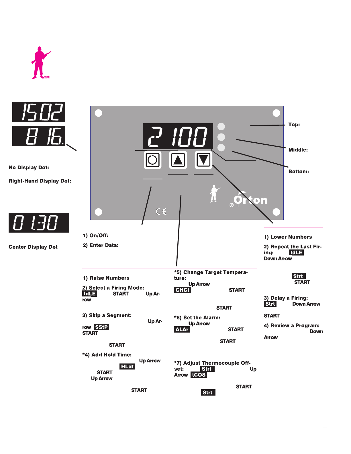
°F
°C
°C Display Dot
Temperature Display
Temperature
display is in °F.
Tem
perature display is in °C.
Seepage13forinstructionson
selecting °F or °C.
Time Display
:Separates hours from minutes. Example: Display shown above
is 1 hour and 30 minutes.
Hr./Min.
When Lit
START/
-
STOP
Enter
Program
SENTRYXpress
MICRO PROCESSOR
START/STOP Key
Starts and stops a firing.
Press after each
programming step. It works like the
Enter key on a computer.
Up Arrow Key
From
press .Press
to select Single-Speed or
Ramp-Hold. Pages 6, 8
During a
Ramp-Hold firing, press the
. will appear. Press
. The current segment ramp
or hold number will appear. To
skip, press again. Page 8
During a
Ramp-Hold firing, press
repeatedly until appears.
Press .Eachtimeyoupress
the , the hold time for the
current segment will increase by 5
minutes. Then press .
Page 8
Program
Review
Run
°F
When Off
°C
When Lit
HIGHER
Skip Seg.
Add Hold
Change Temp.
T/C Offset
Alarm
The Sentry Xpress 4.0 micro processor is manufactured by the
Orton Ceramic Foundation and displays the CE mark.
press repeatedly until
the arrow keys to change the target
temperature for the current seg
ment. Then press .Page9
press repeatedly until
the arrow keys to change the alarm
temperature. Press .Tosi
lence the alarm, press any key.
Page 9
row keys to adjust the controller to
fire hotter or cooler. Press
to return to .Page12
LOWER
Delay
Review
4.0
During a Ramp-Hold firing,
appears. Press .Use
appears. Press .Use
At the display, press
. will appear. Use ar
TM
During a firing,
-
-
-
Indicator
Lights
Light is
on during pro
gramming.
Light is
on during pro
gram review.
Light
blinks during firing.
Down Arrow Key
From press
.Thepro
gram you have selected
will appear one step at a
time. When ap
pears, press .
Page 4
press .
Enter delay time. Press
twice. Page 4
During firing, press
. The program you
entered will appear one
step at a time. Page 4
-
-
From
-
-
IM-221/2-06
*These features are new with the Sentry Xpress 4.0. If your controller does
not have these features, it is an earlier controller.
1
Page 2
Introduction
Contents
The easiest way to learn to operate your
controller is to read this manual while
you are sitting in front of your kiln. Press
the keys as you read the instructions.
Do not worry if you hear a clicking noise
during operation. Mechanical relays click
as they turn the heating elements on and
off. This is normal.
When you first connect the power, the
controllerwilldisplayasoftwarecodeand
then .
If your controller shows instead of a
software code before appears, then
the controller includes only Skip Seg
ment from "Advanced Features" on pages
8 - 9. If your controller shows a software
code before appears, then the controller has all the features in this manual.
Please read the manual. Damage caused
by failure to follow instructions is not
covered by warranty.
Once you learn the basic features of the
Sentry Xpress, you will be able to control
every stage of firing. This offers learning
opportunities and convenience difficult
to imagine with a manual-controlled kiln.
General Guidelines . . . . . . . . . . . . . . . . . 3
Time and Temperature Display . . . . . . . . . . . . . . . . . . .3
Operation Begins from the IdLE Display. . . . . . . . . . . . 3
Thermocouple Inspection . . . . . . . . . . . . . . . . . . . . . . . 3
A Rapid Way to Scroll Numbers . . . . . . . . . . . . . . . . . . 4
Program Review & Repeat Firing . . . . . . . . . . . . . . . . . 4
Delay . . . . . . . . . . . . . . . . . . . . . . . . . . . . . . . . . . . . . . . 4
Power Failures . . . . . . . . . . . . . . . . . . . . . . . . . . . . . . . .4
CPLt Message: Firing Completed . . . . . . . . . . . . . . . . . 4
Thunder Storms and Power Surges . . . . . . . . . . . . . . . 4
Canceling a New Program. . . . . . . . . . . . . . . . . . . . . . . 4
Theory of Operation . . . . . . . . . . . . . . . . 5
Rate . . . . . . . . . . . . . . . . . . . . . . . . . . . . . . . . . . . . . . . .5
Hold . . . . . . . . . . . . . . . . . . . . . . . . . . . . . . . . . . . . . . . . 5
Two Firing Modes: Single-Speed and Ramp-Hold . . . . 5
Temperature Over-Shoot. . . . . . . . . . . . . . . . . . . . . . . . 6
Single-Speed Programming Instructions . . . . . . . . . . . 6
Ramp-Hold Mode. . . . . . . . . . . . . . . . . . . 7
Programming a Cooling Segment. . . . . . . . . . . . . . . . . 7
Ramp-Hold Programming Instructions. . . . . . . . . . . . . 8
Advanced Features . . . . . . . . . . . . . . . . . 8
Skip Segment. . . . . . . . . . . . . . . . . . . . . . . . . . . . . . . . . 8
Add Hold Time . . . . . . . . . . . . . . . . . . . . . . . . . . . . . . . .8
Editing the Target Temperature During Firing . . . . . . . 9
The Alarm. . . . . . . . . . . . . . . . . . . . . . . . . . . . . . . . . . . . 9
Lost Wax Burnout . . . . . . . . . . . . . . . . . . 9
Overview. . . . . . . . . . . . . . . . . . . . . . . . . . . . . . . . . . . . . 9
Burnout Instructions. . . . . . . . . . . . . . . . . . . . . . . . . . . 10
Display Messages . . . . . . . . . . . . . . . . . 10
Error Messages. . . . . . . . . . . . . . . . . . . 11
bAdP / Bad Programming . . . . . . . . . . . . . . . . . . . . . . 11
EtH / Electronics Too Hot . . . . . . . . . . . . . . . . . . . . . . 11
FAIL / Thermocouple Failure . . . . . . . . . . . . . . . . . . . . 11
FE Error Messages . . . . . . . . . . . . . . . . . . . . . . . . . . . 12
FtL / Fired Too Long . . . . . . . . . . . . . . . . . . . . . . . . . . 12
HTdE / High Temperature Deviation . . . . . . . . . . . . . . 12
PF 1 / Power Failure. . . . . . . . . . . . . . . . . . . . . . . . . . . 12
PF 2 / Power Failure. . . . . . . . . . . . . . . . . . . . . . . . . . . 12
PF 3 / Power Failure. . . . . . . . . . . . . . . . . . . . . . . . . . . 12
tC / Thermocouple Failure. . . . . . . . . . . . . . . . . . . . . . 12
tCL / Thermocouple Lag . . . . . . . . . . . . . . . . . . . . . . . 12
tCr / Thermocouple Reversed . . . . . . . . . . . . . . . . . . . 12
©2004, by Paragon Industries, L.P. IM-221/2-06
2 Single-Speed/Ramp-Hold
Thermocouple Offset . . . . . . . . . . . . . . 11
Selecting °F or °C Display . . . . . . . . . . . 11
Trouble Shooter. . . . . . . . . . . . . . . . . . . 13
Controller display is blank. No heat in kiln.. . . . . . . . . 13
Controller display turns on. No heat in kiln. . . . . . . . . 14
Kiln switch box ½ amp fuses keep blowing.. . . . . . . . 15
Index. . . . . . . . . . . . . . . . . . . . . . . . . . . . 15
Shorthand Instructions. . . . . . . . . . . . . 16
Page 3
Safety
General
The warranty on your Sentry Xpress
controller does not cover damage from
overfiring, regardless of the
circumstances. It is the operator’s
responsibility to make sure the kiln turns
off at the proper time.
When the kiln is not in use, disconnect the
power.
Do not leave the kiln unattended, especially
near the expected shut-off time.
Wear firing safety glasses when looking into the
firing chamber of a hot kiln.
Do not touch hot sides of kiln. Keep unsuper
vised children away.
Install your kiln at least 12 inches from any wall
or combustible surface.
Do not open lidor dooruntil kiln has cooled and
all switches are off.
Fire only in a well-ventilated, covered and protected area away from combustible materials.
Keep cordset away fromhot sides of kiln or furnace.
DANGEROUS VOLTAGE! Do nottouch heating elements with anything. Disconnect before
servicing.
When vacuumingthe kiln, keepthe nozzle away
from the controller. Vacuum cleaners create a
static charge that can damage the controller.
Guidelines
Time and Temperature
Display
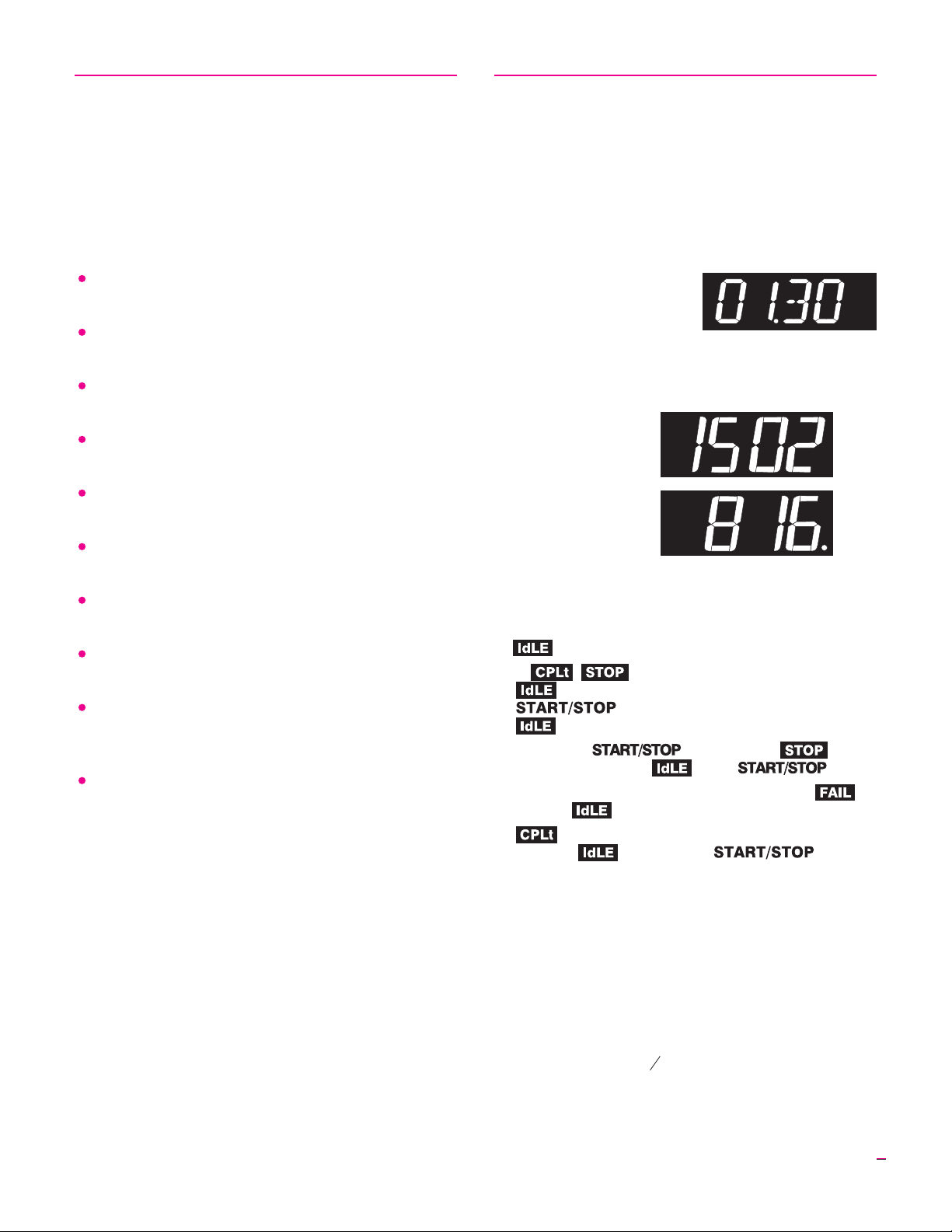
Center Dot: Time
A center dot appears dur
ing time display. It separates
hours from minutes. (Exam
ple: 1 hour, 30 minutes dis
plays as 01.30.) During tem
perature display, the dot
disappears.
Right-Hand Dot: °C
-
When temperature
is displayed in °C, a dot
appears in the lower
right. In °F display, it
disappears. You can
choose between Fahrenheit and Celsius display. See page 13.
Operation Begins from
the IdLE Display
must appear before you can fire the kiln.
I
If , , or other message appears instead of
when the kiln is first turned on, press the
key (the key with the circular arrow).
will appear.
I
If you press during a firing, will ap
pear. To get back to , press again.
I
If the display shows an error message such as in
stead of , see page 11.
I
(firing completed) appears at the end of a firing.
To make appear, press .
-
-
-
The center display dot indicates
-
time instead of temperature.
°F
°C
-
-
Thermocouple Inspection
The small rod protruding into the firing chamber is the
temperature sensor, or thermocouple.
CAUTION: Bumping the thermocouple can push it
out of the firingchamber. Thiscould causean overfire!
Bumping the thermocouple could also cause inaccu
rate readings.
I
A 1/8” diameter thermocouple should extend into the
firing chamber ½” -
I
A ¼”diameter thermocoupleshould extendinto thefir
ing chamber ¾ - 1” or more.
I
Keep shelves, posts and ware 1” - 1 ½” away from the
thermocouple.
5
”.
8
-
-
3
Page 4
ARapidWayto
Scroll Numbers
During programming, hold an arrow key down several
seconds, and numbers will begin to scroll rapidly. Ordi
narily, you would press to raise a number and
to lower it. But sometimes it is faster to press
the opposite key. This is because the numbers scroll below
0000 to the highest number, and vice versa. Examples:
I
To program a 99.59 hour Hold when the display shows
00.00, press the once.
I
To program a FULL rate when the display shows 0000,
press the once.
I
To program a temperature of 200°F when the display
shows 1800°F, press the . That is faster than
pressing the .
Program Review &
Repeat Firing
Program Review lets you check that the information
programmedinto thecontrolleris correct.ProgramReview
shows the values for the program in active memory. Use
Program Review from to repeatthe lastprogram you
fired.
I
key. The rate, temperature, hold, etc. will
display one after the other. Firing will continue.
I
Press the key. After rate, temperature, hold, etc., will appear. Press .
will appear, and the kiln will begin firing the program
just reviewed.
Press the
Note: Press during delay to end the delay and
begin the firing. The maximum delay is 99 hours and
59 minutes.
-
Power Failures
After a power failure, the controller will continue firing
provided that:
I
The kiln temperature is above 212°F / 100°C when the
power comes back on.
I
The temperature dropped no more than 72°F / 40°C
while the power was off.
Power Failure Messages (see page 12)
The power failed during a cooling segment, and
the kiln cooledpast thetarget temperaturewhile thepower
was off.
The power failed during firing and kiln tempera
turewas below212°F / 100°Cwhen thepower cameback on.
The power failed during firing and temperature
dropped more than 72°F / 40°Cby the time the power came
back on.
CPLt Message: Firing
Completed
When thefiring hassuccessfully completed, the Sentry
Xpress will shut off power to
the elements and sound an
alarmfor 30seconds. Thenthree messageswill cycle oneafter the other:
(complete)
Firing time in hours and minutes
-
Delay
Delay is a count-down timer.The kilnbegins firingwhen
the timerruns outof time.Use Delayto fit a firinginto your
schedule.
CAUTION: For safety,do not leavethe kilnalone dur
ing a delay or a firing. We cannot guarantee your kiln
against overfiring even though the controller is auto
matic.
After you have entereda program and the control
ler is ready to begin firing, will appear.
Press the key once. will ap
pear, alternating with .
Use the arrow keys to enter delay time. (The deci
mal separateshours andminutes. Example:1 hour
and 10 minutes = 01.10.) Then press twice.
will appear, alternating with time left until
the firing begins.
4 Single-Speed/Ramp-Hold
-
-
-
-
-
The current kiln temperature
Press to return to .
Thunder Storms and
Power Surges
Unplug the kiln or disconnect the power when the kiln is
not in use, especially during thunder storms and in areas
with frequent power surges. If the kiln is part way through a
firing when a storm begins, it is probably okay to continue
the firingwith closesupervision. Donot leavethe kilnunat
tended.
Canceling a New Program
If you do not touch the keys for one minute during pro
gramming, the controllerwill go back to the display.
The controller will also discard the program you were en
tering and will retain the previous program in memory.
This is useful if you change your mind during program
ming and decide to keep the previous program. Instead of
completing the newprogram, waita minuteand letthe con
troller return to .
-
-
-
-
-
Page 5

Theory of Operation
The temperature you are firing to is called the target
temperature. After the controller reaches the target tem
perature, it can also hold that temperature.
The controller firesat acontrolled heating rate.The rate
is figured in degreesper hour. If you selecteda rate of100°
per hour, it would take10 hours for the kiln toreach 1000°.
Rate is similar to “miles per hour.”
In summary, the controller does three basic tasks:
1) It fires at a controlled heating rate, or speed, mea-
sured in degrees of temperature change per hour.
2) It fires to a target temperature.
3) It can hold the target temperature.
The controller fires in segments, or stages. A segment is
a given heatingrate to atarget temperature. Shownabove is
a segmentwith arate of625° perhour, a target temperature
of 1250°, and a hold of one hour.
Heating rate is figured in degrees per hour. The recom
mended heating rate for the material you are firing is usu
ally available from your supplier. It also varies depending
on the thickness of the material.
To figure how long a firing segment will take, subtract
the current temperature from the target temperature and
divide the resultant temperature bythe heating rate.In the
diagramabove, thefiring timeis 1250°- 80° (roomtempera
ture) = 1170 ÷625 = 1.87 hours.
The controller can fire up to 8 segments per firing. One
segment is often all that is needed, though.
After the controller has finished firing the last segment,
it will turn off power to the elements.
Note: If youenter a rate of 0000 in segment 1,or if the
target temperature in segment 1 is lower than the cur
rent temperature, will appear in the display.
-
Rate
Each segment must include a rate, which is degrees of
temperature change per hour.
The kiln will fire at full power when the rate is
1799°F/999°C. Full power displays as .
-
Note: To enter full power from , press the
key once.
Hold
Hold is the length of time that you want the kiln to remain at the target temperature. Hold is also called soak or
dwell time. Hold maintains a steady temperature for the
length of time you specify. You can use Hold in both heating-up and cooling-down segments.
When Hold is set to 99.59 hours, the controller will remain at that temperature indefinitely, until you press
. To enter a 99.59 hour Hold, press the
once from 00.00 during programming.
Note: During a Hold, the display flashes between the
Hold temperature and time left in Hold.
Two Firing Modes:
-
-
Single-Speed and Ramp-Hold
To give you greater flexibility, your controller has two
firing modes:
Single-Speed Mode (see next page)
Often times, all you will need is Single-Speed mode,
which has one segment that includes a rate (temperature
change per hour), a target temperature, and (if needed)
hold time.
In Single-Speed mode, you can choose one of five firing
speeds. Then enter the temperature you are firing to.
Ramp-Hold Mode (see page 7)
Ramp-Hold mode offers much greater flexibility than
Single-Speed mode. Use Ramp-Hold to create custom fir
ings with up to 8 segments. The controller can store 4
-
5
Page 6

Ramp-Hold programs inmemory. Programsare numbered
Pro1 - Pro4.
Type of Firing Suggested Firing Mode
Enameling Single-Speed
Silver Clay Single-Speed
Glass Bead Annealing Ramp-Hold
Glass Fusing Ramp-Hold
Glass Slumping Ramp-Hold
Lost Wax Ramp-Hold
Selecting a Firing Mode
From display, press once.
Press the keyseveral times. You will see
the following display messages:
SPd1:
Single-Speed 1 / 200°F/111°C rate per hour
SPd2:
Single-Speed 2 / 500°F/277°C rate per hour
SPd3:
Single-Speed 3 / 1000°F/555°C rate per hour
SPd4:
Single-Speed 4 / 1500°F/833°C rate per hour
SPd5:
Single-Speed 5 / Maximum rate
PrO1:
Ramp-Hold, Program 1
PrO2:
Ramp-Hold, Program 2
PrO3:
Ramp-Hold, Program 3
PrO4:
Ramp-Hold, Program 4
Note: Your controllermay have moreRamp-Hold pro
grams than the 4 shown above.
To select a firing mode, see the boxed programming in
structions on this page and page 8. Or to get back to
, press several times until ap
pears.
-
Temperature Over-Shoot
When akiln is heatedtoo fast, it mayover-shoot the tar
get temperature,especially insmall kilns at lower tempera
tures. To avoidthis, add an extra segment in a Ramp-Hold
program to slow the firing. (See the next section.) The seg
ment with the slower rateshould begin approximately 40° 60° below the target temperature.
Single-Speed Programming
Instructions
Note: Single-Speed firingis allyou will everneed if
you are only going to a temperature and holding.
From , press .
Use the key (not the )to
select a firing rate (temperature rise perhour)
from 1 through 5. (Ignore - .)
/ (200°F or 111°C)
/ (500°F or 277°C)
/ (1000°F or 555°C)
/ (1500°F or 833°C)
/ (Full Power)
Then press .
or and the target temperature
from the last firing will appear. Use the arrow
keys to change the target temperature. Then
press .
and the hold time from the last firing
will appear (e.g. 1 hour 10 minutes = 01.10).
Use the arrow keys to change the hold time.
Then press . (No hold = 00.00)
will appear. Press to begin firing.
will appear, the Run indicator light will
begin blinking, and the kiln will begin firing.
To stop a firing before completion, press
. willappear, alternatingwith total
firing time and kiln temperature.
Note: Do not be concerned if your kiln makes a
clicking sound during firing. Kilns use relays to
power the elements. The relays click each time
-
-
-
-
-
their electrical contacts come together.
Note: The firing speed you select (see step 2
above) is a pre-programmed speed. The kiln’s ac
tual firing speed may be less, dependingon thekiln
model, available voltage, and density of the load
you are firing.
When thekiln fires to completion,the controllerwill
beep for 30 seconds. The display will show the follow
ing:
I
Firing time
I
Present temperature
I
To return to , press .
= Fired to completion
-
-
6 Single-Speed/Ramp-Hold
Page 7

Ramp-Hold Mode
You can make your own firing programs and store them
in the controller’s memory. A firing program tells the kiln
how fastto fire,and towhat temperature.The simplestpro
gram is one segment. You can use up to 8 segments with
your controller in Ramp-Hold mode.
Each segment includes a firing rate and firing tempera
ture. You canalso soak,or hold,the temperaturefora spec
ified period.
The Parts of a Segment
I
Rate (temperature change in degrees per hour)
I
Target temperature
I
Hold at the target temperature (not always used)
The controllercan retainfour programsin memoryeven
when power is turned off. Programs are numbered Pro1 Pro4.
The first message toappear afteryou plugin yourSentry
Xpress is . Press . Then use the key
to scroll through these messages:
.
To use Ramp-Hold mode for the first time, select
. Youdo that by pressing the key after
appears. Then follow the boxed instructions on page 8 to
enter temperature, heating rate, etc.
is Program 1. When you fire the kiln again, you
can repeat Program 1 by selecting . (See page 4.)
When you are ready to fire a different program, select
, which is Program2. Thenenter temperatures,heat
ing rates, etc. Select Program 3 and 4 the same way.
A program canhave up to8 segments,butyou don’thave
to use all 8 segments. Use only the number needed per fir
ing. Oftenone segmentis allyou willneed. Zeroout theun
used segments. The instructions on page 8 explain how to
do that.
To over-write a program, select it and enter new rates
andtemperatures. Thisautomaticallyover-writes theprevi
ous program.Write downyour programsin anotebook and
record firing results for all firings.
Programming a
Cooling Segment
For controlled cooling, program a segment to a lower
target temperature than that of the preceding segment.
Example: You fire at a rate of 500°F per hour to 1450°F
with your first segment. You want the kiln to cool at a rate
of 100°F per hour down to 700°F. Here is how you would
program the two segments:
Segment °F/°C °F/°C Hold
1 500/277 1450/788 00.00
2 100/55 700/371 00.00
The first segment is the heating segment. The second
one isthe cooling segment. The controller does not use mi
nus numbersfor cooling.Just entera lowertarget tempera
ture than that of the previous segment.
-
-
-
If you prop the lid or door for a fast cooling, program a
fast coolingrate forthat segment.If youlower thetempera
ture quicklyby propping the lid but programa slow cooling
rate, the controller will just raise the temperature again.
Example: Some glassartists flash-coolthe glass justafter
it fuses. They open the door a few inches to remove heat,
then close it again. This takes the glass down rapidly
through the devitrification range.To program a flash-cool,
use maximum rate. This shuts off the heating elementsdur
ing that segment, allowing the kiln to cool rapidly.
Note: During fastcooling, do not open thedoor all the
way. Do not force-cool the kiln with a fan.
Note: Youmay get anFTL error message(page 12) if
you program a cool-down target temperature that is
close to room temperature. This is because the kiln
cools more slowly as it approaches room temperature,
causing the error code.
Rate Temp.
A Ramp-Hold
Practice Program
To practiceusing the controller, we will enter a program
that includes three segments. The last segment is a cooling
segment.
-
-
-
-
Using the programming instructions on the next page,
enter this firing schedule. Then use Program Review (page
4) to check for accuracy.
Make asimple chart like the one above whenplanning a fir
ing program.
PrO1
rA1 = 250
°F1=750
HLd 1 = 00.00
rA2 = 900
°F 2 = 1425
HLd 2 = 00.30
rA3 = 150
°F3=750
HLd 3 = 00.00
rA4 = 0000 (zeroes cancel segments 4-8)
-
-
-
-
-
7
Page 8

Ramp-Hold Programming
Instructions
Advanced
Note: You have up to 8 segments available in
Ramp-Hold. If you don’t need all 8, zero out the
unused segments. (See step 6 below.)
From , press .
Press the key (not the ).
and are
Ramp-Hold programs. When the one you
want appears, press . (Ignore -
.)
will appear. Enter firing rate (tempera
ture change per hour) for segment 1. (1° =
slowest rate. 1799°F/999°C = full power.)
Then press .
or andthe targettemperature from
the last firing will appear. Use the arrow keys
tochange thetemperature.Then press .
and the hold time from the last firing
will appear (e.g. 1 hour 10 minutes = 01.10).
Use the arrow keys to change the hold time.
Then press . (No hold = 00.00)
Continue entering values for the segments
needed. When appears for thenext segment that you don’t need, select . Then
press . This will zero out the remaining
segments. (Example: You need only 1 segment. When appears, enter .)
will appear. Press to begin firing.
will appear and the Run indicator light
will begin blinking. The kiln is now firing.
To stop a firing before completion, press
. willappear, alternatingwith total
firing time and kiln temperature.
Features
Skip Segmentworks only inRamp-Hold programs. Add
Hold Time, Temperature Edit, and Alarm work in both
Single-Speed and Ramp-Hold firings.
Skip Segment
Skip Segment jumps the firing from the current segment
to the next one.
-
During a Ramp-Hold firing, press the .
will appear.
Press . The current segment ramp or hold
number will appear.
Press again. (If you change your mind and
don’t want toskip thatsegment, don’tpress
after appears. The firingwill continuein the
same segmentand the temperaturewill appear af
ter one minute.)
Skip Segment skipsto the rampof thenext segmentfrom
either a ramp or hold of the current segment. (Skip Segment does nothing during the final segment. To end the final segment, press .)
Skip Segment Example
You have programmed a target temperature of 1425°F for glass fusing,
followed by a segment for controlledcooling. Watching the
glass through the peephole, you notice that the glass edges
have rounded nicely at 1315°. Use Skip Segment to end the
firing segment and to begin the one for slow cooling.
Note: Make a note of the temperature at which the
glass fused. Program that temperature for the nextfir
ing of that type of glass.
-
-
Note: Do not be concerned if your kiln makes a
clicking sound during firing. Kilns use relays to
power the elements. The relays click each time
their electrical contacts come together.
Note: The kiln’sactual firingrate maybeless than
the rate you programmed, depending on the kiln
model, available voltage, and density of the load
you are firing.
When the kiln fires to completion, it will beep for30
seconds. The display will show the following:
I
Firing time
I
Present temperature
I
To return to , press .
= Fired to completion
8 Single-Speed/Ramp-Hold
Add Hold Time
Add Hold Time adds 5 minutes to a hold. It is designed
for ceramists who watch witness cones and for glass artists
who watch the glass near the end of firing.
During a firing, pressthe repeatedly un
til appears.
Press . The hold time for the current seg
ment will appear.
Press the .Each timeyou pressthe
, the hold time will increase by 5 minutes.
Press . The normaltemperaturewill appear.
Note: Add HoldTime willadd 5 minutesto ahold even
if no hold had been programmed.
-
-
Page 9

Editing the Target
Temperature
While the kiln is firing, you can change the target tem
perature of the current segment. (Ramp-Hold: You can
edit onlythe segment that is firing.So if thefirst segment is
the currentone, you can edit only the firstsegment. To edit
other segments, waituntil thefiring hasprogressed tothose
segments.)
Even if the current segment has already started its hold
time, you can still edit the segment's target temperature.
The controller will go back out of hold and fire to the new
target temperature at the original rate. (You cannot edit
the rate, however.)
During a firing, press the repeatedly until
appears.
Lost Wax
-
Burnout
CAUTION: Only kilns with vent holes are designed
for lost waxburnout. However,you maybe able touse a
kiln without the vent hole provided that you open the
door ½” during venting.
CAUTION: Always use a wax tray.
Note: These instructions apply to injection wax that
melts at 200°F, not pattern waxes and plastics that
melt at higher temperatures. If smoke appears during
wax elimination, turn off the kiln. Smoking wax means
the kiln fired hotter than 300° / 148°C.
Press . The target temperature for the cur
rent segment will appear.
Use the arrow keys to change the target tempera
ture.
Press . The normal kiln temperature will ap
pear, and the kiln will begin firing to the new target
temperature.
-
-
-
The Alarm
While the kiln is firing, you can set the alarm, which
sounds when the kiln reaches the alarm temperature. Use
the alarmas areminder to look at the glass during fusingor
slumping, to look at witness cones, to close the lid from
vented position, etc.
You can enter only one alarm temperature at a time.
However, after the alarm beeps, you can set the alarm for
another temperature, asmanytimes asyou want, duringthe
firing. Enteringan alarm temperatureautomatically erases
any previous alarm temperature.
Note: The alarm temperaturethat youset duringa fir
ing must be higher than the current display tempera
ture. The alarm is designed only for higher tempera
tures and not for cooling temperatures.
During a firing, press the repeatedly until
appears.
Press . The current alarm temperature will
appear.
Use the arrow keys to change the alarm tempera
ture.
Press . The normal kiln temperature will ap
pear.
To silence the alarm when it sounds, press any key.
Note: If youdo notwant touse the alarm,set the alarm
temperature to 32°F / 0°C. This setting will turn off the
alarm feature.
-
-
-
-
-
Overview
Lost waxcasting is theprocess of carving a shape in wax,
making a mold, and then casting that shape in metal. After
the wax has been carved, a mold is made of the wax shape.
The mold is a negative image of the wax. The wax is later
melted out of the mold through hollow channels called
sprues.
Lost wax burnout is the process of preparing a casting
mold for the melted metal that will be poured into it. The
steps in lost wax burnout:
Melt the wax from the mold.
Remove wax from the kiln before raising the tem-
perature higher than 300°F/148°C.
Harden the mold at high temperature.
Maintain the mold at the casting temperature rec
ommended forthe type of metal that willbe poured
into the mold.
CAUTION: Prevent wax or carbon from contacting
the kiln’s wallsand elements.Carbon build-upinside a
kiln ruinsthe interior. Carbon conducts electricity and
causes elements to short circuit. Damage to elements
from contact with foreign materials is not covered by
warranty.
-
A Sample Program
See instructions on page 8 to enter this program:
Rate Temp.
Segment °F/°C °F/°C Hold
1 500/277 300/148 01.00
2 500/277 1350/732 01.00
3 450/250 800/426 02.00
Segment 1 heats the wax to 300°F /148°C and holds it for
one hour, allowing it to drip from the mold.
Segment 2 hardens the mold.
9
Page 10

Segment 3 lowers temperature to 800°F/426°C, the typi
cal casting temperature for silver. (Most types of gold cast
at 900°F / 482°C.)
Note: Casting temperature depends on the size of the
mold. The temperatures above are only a guide. See
your jewelry supply dealer for temperature
recommendations.
Burnout Instructions
Place a metaltray insidethe kilnon three½” posts.
Place the mold on a wire mesh screenon topof the
tray. The mold’s sprue hole should be down. The
tray will catch melting wax as it drips from the
sprue hole.
Keep the kiln’s vent hole(s), if any, open during
wax elimination. If the kiln has no vent hole, leave
the dooropen ½”. This allows fumes to escape the
kiln. Heat the kiln to 300°F / 148°C and hold it at
that temperature for at least one hour.
-
Display Messages
(Page 9) Ready for you to enter an alarm
temperature. When the kiln reaches that tempera
ture, the alarm will sound. ( also flashes
when the alarm sounds.)
(page 9) Ready for you to edit the target
temperature of the current Ramp-Hold segment
during firing. Example: You are fusing glass to a
temperature of 1450°F. At 1445°F, you look at the
glass through a peephole and realize that the glass
will need at least another 50° to fuse fully. Change
the target temperature to 1500° without having to
turn off the kiln to reprogram it.
-
CAUTION: Do NOT heat the wax above 300°F /
148°C. Hold at 300°F / 148°C for at least one hour.
During this hour, the wax will melt from the mold and
drip into the tray. If the kiln gets hotter than 300°F /
148°C, the wax may smoke and deposit carbon inside
your kiln, causing expensive damage.
After one hour at 300°F / 148°C,open the kiln. Re-
move the moldand wax tray.Pour thewax fromthe
tray and leave the tray out of the kiln until your
next wax elimination. (Do not leave the trayin the
kiln!)
Heat the mold to the temperature recommended
by your jewelers’ supply house where you pur
chased the mold material. This is usually around
1350°F / 732°C.
Lower thetemperature to the casting temperature
of the metal. Hold at that temperature until you
are ready to begin casting. Remove the mold with
tongs. Wear protective gloves and safety glasses.
-
Saving a Carbon-Damaged Kiln
If you follow the above directions, your kiln should be
safe from wax damage. In some cases, a small amount of
carbon may form on the walls over a period of time. This is
due to the burning of wax residue that was leftin the mold.
For this reasonwe recommendthat youperiodically fire the
kiln to 1500°F / 815°C as follows:
Open the vent cover(s) or leave the door ajar ½”.
Fired to completion.
(page 4) Delay is a count-down timer that
starts the firing when the time runs out.
or (and temperature) (pages 6, 8)
The controller is ready for you to enter the target
temperature (the temperature that the kiln will fire
to). Each segment in Ramp-Holdmode has a target
temperature.
Full power firing rate. At this setting the kiln
will fire at its fastest rate. There are two ways to select full power:
1) Select in Single-Speed mode.
2) Select a rate of 1799°F/999°C at the prompt
in Ramp-Hold mode. A fast way to do this is to press
the key once from . will ap
pear.
(pages 6, 8) Hold time of a segment,
shown in hours and minutes. (Example: 2 hours
and 15 minutes = 02.15)
(Page 8) Add HoldTime: During a firing, you
can extend the hold time of a segment without hav
ing tofirst stopthe firing to reprogramthe controller.
-
-
Fire the kiln empty to 1500°F / 815°C at a rate of
300°F / 166°C with a one hour hold (01.00).
10 Single-Speed/Ramp-Hold
(page 3) The controller is ready for you to en
ter a program or to begin a repeat firing.
Firing has begun. A moment after ap
pears, you will hear the relay(s) clicking.
-
-
Page 11

(pages 7, 8) These
are Ramp-Hold programs stored in memory.
etc. (Rate) (page 8) This appears in
Ramp-Hold programming for each segment. 1, 2,
etc. are segment numbers. Enter the rate of temper
ature change for that segment. Rate is figured in de
grees of temperature change per hour. Example:
A temperature rise of 100° in two hours = 50° rate.
A temperaturedrop of200° in onehour =200° rate.
(page 6)
These are preset firing rates, or speeds, in Sin
gle-Speed mode.
(Skip Step) (page 8) This message appears
when you press the key during a
Ramp-Hold firing. You can skip out of a segment
into the next segment.
The firing was stopped by pressing
.
The "Ready to Start" message appears after
programming a firing. Press to begin firing.
Thermocouple Offset (press the ) and Delay (press the ) are accessed from the
message.
Error Messages
bAdP / Bad Programming
-
-
-
The kiln will not fire because a) the Ramp-Hold pro
gram just entered hasa rate of 0000 in segment 1, or b) the
target temperature in Single-Speed or segment 1 of
Ramp-Hold is lower than the current temperature.
EtH / Electronics Too Hot
The circuit board temperature is above 176°F / 80°C.
Press any key to return to .
To lower the board temperature, use a fan to blow air
across the kiln switch box into the louvers. (But do not blow
air into the kiln’s peepholes.) If you have more than one
kiln in the room, place them farther apart. Never allow the
firing room temperature to exceed 110°F / 43°C. (Measure
room temperature three feet away from the kiln.)
FAIL / Thermocouple Failure
The thermocouple, or temperature sensor, failed during
firing. Causes:
I
Defective thermocouple or disconnected/loose wires
I
Defective controller
I
Electrical noise
-
Thermocouple Offset (Page 12). Adjust the
controller to fire hotter or cooler.
Thermocouple Paperclip Test
Check the thermocouple wire connections. (See your
kiln instruction manual.) If connections are tight, perform
this test:
UNPLUG the kiln or disconnect the power. Re
move thecontroller. Removethe two thermocouple
wires from the back of the controller.
Cut a thin paperclip in half. Insert a U-shaped
paperclip piece, or other piece of thin wire, where
you removed the thermocouple wires.
Plug in the kiln. If the controller displays room tem
perature, replace the thermocouple. If it shows
, return the controller for repair or
replacement.
-
-
11
Page 12

FE Error Messages
FE 1 Memory Read/Write Failure
FE 2 RAM Failure
FE 3 OEM Factory Data Corruption
FE 4 Thermocouple “Noise”
FE 5 Software Error
To return to from an FE code
Trypressing anykey. If thatdoesn’t work, turnthe power
off for 10 seconds. Call the factory if the error message re
mains when you turn the power back on.
If youget an message, checkthe wireconnections
going from the back of the controller to the thermocouple.
A loose connection can cause the message.
FtL / Fired Too Long
This messageappears when both of the following condi
tions are met:
I
The temperature rise or fall is less than 27°F / 15°C per
hour.
I
The firing is 2 hours longer than programmed.
Programminga coolingsegmenttarget temperaturethat
is belowor even close to room temperaturecan also trigger
the message.
See “Controller display turns on. No heat in kiln,” page
14.
PF 3 / Power Failure
The power failedduring firing andtemperature dropped
more than72°F / 40°Cby the time the power came backon.
The kiln will not resume firing. To return to the dis
play, press any key.
tC / Thermocouple Failure
The thermocouple failed during the display. See
the "paperclip" test under "FAIL," page 11.
-
tCL / Thermocouple Lag
The heating rateis slower than9°F /5°C perhourand the
controller temperature is more than 100°F / 56°C away
from the actual kiln temperature. To return to the
display, press any key. Causes:
I
On kilns that use a portable controller, the thermocou
ple has fallen out of the firing chamber.
-
I
A bare spoton thethermocouple lead wireshas touched
a groundedobject inside the kiln switch box causing the
thermocouple to short out.
Check for wornor burnedout elements,defectiverelays,
low voltage and defective thermocouple.
tCr / Thermocouple Reversed
Thermocouple lead wires are reversed. Check that the
thermocouple lead wires are connected to the correct terminals. See your kiln’s wiring diagram.
-
-
HtdE / High Temperature
Deviation
Causes:
I
During a heating-upramp or a hold, the temperature is
100°F / 56°C above the programmed temperature.
I
During a cooling-down segment, the temperature is
100°F / 56°C higherthan the segment’s starting temper
ature.
I
A fastrate caused thecontroller to overshootthe target
temperature.
Also, check for a stuck relay.
PF 1 / Power Failure
The power failed during acooling segment, and the kiln
cooled pastthe targettemperature whilethe powerwas off.
The kiln will not resume firing. To return to the dis
play, press any key.
PF 2 / Power Failure
The powerfailed duringfiring and kiln temperature was
below 212°F / 100°C when the power came back on. The
kiln will not resume firing. To return to the display,
press any key.
Thermocouple Offset
-
-
You can adjust the controller to fire up to 20°F / 11°C
hotter or cooler than the zero factory setting.
From , press the key. Afterrate,
temperature, hold, etc., will appear.
With shown in the display, press the
key.
will appear. Press thearrow keys to change
the controller temperature.
Pressthe keyto returntothe display.
To fire the controller, press . will ap
pear. Or toreturn to , press two more
times.
-
12 Single-Speed/Ramp-Hold
Page 13

Selecting °F or
Trouble Shooter
°C Display
The controller can display temperature in either °F or
°C. If your controller showsa small display dot in the lower
right cornerof thedisplay, thetemperature shown is °C. No
dot means °F. To change temperature display:
UNPLUG kiln or disconnect power.
Remove the four screws that hold the controller to
the front ofthe kiln.Carefully remove thecontroller
from the kiln. Leave the wires attached to the con
troller.
Look atthe backof thecontroller. You willfind aset
of connector pins near the bottom labeled “C/F.”
When a jumperis placedon theC/F pins,the display
reads°F. Whenthejumper isremoved, display reads
°C. Remove or insert the jumper as desired. (You
can purchase the jumper from a computer supply
store if necessary.)
-
Problem: Controller display is
blank. No heat in kiln.
I
Is the kiln connected to the power?
I
Has the circuit breaker tripped or fuse blown?
I
Is power reaching the wall receptacle?
Test with a voltmeter or a test light if you are not sure.
I
Has the kiln switch box
½ amp fuse blown?
The kiln’s ½ amp fuse is
located in the kiln switch
box. Remove by pressing
the fuse holder and turning
counter-clockwise half a
turn. Check the fuse by
placing the probes of an
ohmmeter on the ends
of the fuse. If the ohm
meter reads less than
an ohm (digital meter)
or reads 0 ohms (analog meter), the fuse is
okay. If the reading is
OPEN (digital meter)
or infinity/no needle
movement (analogmeter), the fuse is bad.
Replacement fuse:
AGC 1/2 A 250V AC
I
Is the controller receiving power? Test the power IN
PUT connections on the back of the controller with a
voltmeter.
Controller Power Input Test
Unplug the kiln. Remove the 4 screws holding the con
troller faceplate to the switch box. Lift faceplateout of box
and let theboard hangon thebox withthe backof theboard
facing you. Plug the kiln back in. Touch voltmeter probes
-
-
-
The C/F jumper terminal is on the back of the controller, circled above.
Install thecontroller beingcareful not to jar compo
nents on the back of the controller against the kiln
case.
-
Touch the voltmeter probes to the white and orange wires to test voltage
going to the controller. The voltmeter must be in AC mode.
13
Page 14
(in AC mode) to both INPUT connections (the white and
orange wires). (See photo on previous page.)
CAUTION: Do not let the back of the board touch a
grounded object. Make sure the voltmeter is in the AC
modewhen placingtheprobes onINPUTconnections.
Problem: Controller display
turns on. No heat in kiln.
I
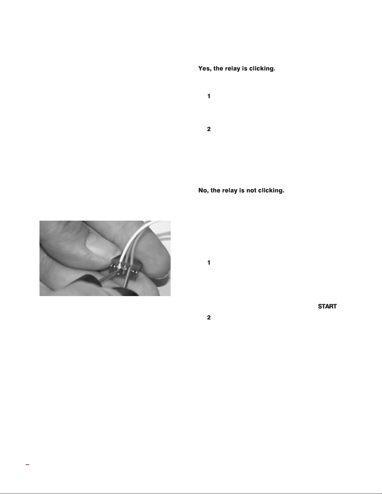
Is the relay making its normal clicking sound?
Controller Power Input Test Result: No voltage
UNPLUG kiln. Check the switch box for disconnected
wires betweenthe cord, transformer, and controller. If wir
ing is okay, replace the transformer.
Controller Power Input Test Result: 20 - 24 volts AC
Correct current is reaching the board from the trans
former. Butsince the boardis not lightingup, it isprobably
defective.Return thecontrollerfor repairor replacement.
Controller Power Input Test Result: less than 20 volts
Did you recently replacethe transformer? It maybe the
wrong voltage.The voltageis below20, whichis notenough
power for the controller. To find out the cause of low volt
age, continue below:
Controller Input Test #2
The back of the board is still facing you and the kiln is
pluggedin. RemovetheINPUT plug,which is thewhite, or
ange, and bluewires, fromthe backof the controller.Touch
a voltmeter probe to the white wire and the other probe to
the orange wire.
Input Test #2 with disconnected plug: Touch the voltmeter
probes to the white and orange wires to test voltage going to
the controller. The voltmeter must be in AC mode.
Input Test #2 Result: Less than 20 Volts AC
There are two possible reasons: 1) Low voltage at the
wall receptacle;2) defective transformer. Ifwall receptacle
voltage is correct, replace the transformer.
Input Test #2 Result: 20 - 24 Volts AC
The transformer is sending correct voltage to the con
troller. Yet when the INPUT plug was connected to the
controller, voltage wasless than20. This means thecontrol
ler isdraining the voltage and may bedefective. Returnthe
controller for repair or replacement.
Test the elements with an ohmmeter:
Element Resistance Test
-
-
-
-
-
-
UNPLUG kiln/disconnect the power. Open the
kiln’s switch box. Make sure the wires connecting
the relay to the elements are secure. If connec
tions are okay, continue to step 2:
Touch theohmmeter leadsto the twoelement con
nectors of each element. A no-needle-movement
reading on an analog meter, or OPEN on a digital
meter, indicates a broken element.
If the elements check out okay, replace the relay.
Note: To replace relay, see your kiln’s instruction and
service manual.
We know thecontroller isreceiving voltage,because the
display is lit. But the voltage from the transformer may be
too lowto powerthe relays.Perform the“Controller Power
Input Test,” page 13. If your controller passes the Input
Test, perform the “Controller Power Output Test”:
Controller Power Output Test
Is the controllersending voltagetothe relay?Test OUT-
PUT with a voltmeter:
UNPLUG thekiln/disconnect the power. Remove
the 4screws holdingthe controller faceplate to the
switch box. Lift faceplate out of box and let the
controller hang on the outside of the box with the
back of the board facing you. Then plug the kiln
back in.Program thecontroller tofire to 1000°F at
FULL rate in Ramp-Hold mode. Press .
Put the voltmeter in DC mode. (It must be in DC
mode when testing OUTPUT voltage.) Touch
probes to the red wire and black wire connections.
Measure voltage when the relay clicks on.
Output Test Result: No voltage at red and black wires
The controller is not sending powerto the relay.Return
the controller for repair or replacement.
Output Test Result: 10 - 14 v. at red and black wires
The controlleris sendingcorrect powerto therelay. Un
plug kiln/disconnect power. Remove the kiln switch box.
Look for disconnected wires between the controller, relay
and elements. Check the wiring diagram to be sure wires
are connected tothe correctterminals.Be sureconnections
are tight. If the wiring is okay, replace the relay.
-
-
-
14 Single-Speed/Ramp-Hold
Note: To replace relay, see your kiln’s instruction and
service manual.
Page 15

Problem: Kiln switch box ½
amp fuses keep blowing.
I
What size fuse are you using? Correct fuse:
AGC ½ A 250V AC
If the fuseis the correctsize, perform thefollowingtest:
Kiln Switch Box ½ Amp Fuse Power Test
UNPLUG the kiln/disconnect the power. Remove
the 4 screws holding the controller board faceplate
tothe switchbox. Lift faceplateoutof boxandlet the
board hang on the outside of the box with the back
of the board facingyou. Disconnect both wire plugs
from the back of the controller. Then plug the kiln
back in. Apply power to kiln. If the ½ amp fuse
blows, replacethe transformer. (If the fusedoes not
blow,the problemisa boardorrelay. Gotostep 2.)
Connect the INPUT plug (orange, blue, and white
wires) to the board again. Leave off the OUTPUT
wire plug (the one with the red and black wires).
Program the controller to fire to 1000°F at FULL
rate in Ramp-Hold mode. Press . If the fuse
blows, replaceor servicethe board. (If the fusedoes
not blow,the problemis causedby a short in thecoil
of a relay. Go to step 3.)
Index
Add Hold Time. . . . . . . . . . . . . . . . . . . . . . . . . . . . . . . . . 8
alarm . . . . . . . . . . . . . . . . . . . . . . . . . . . . . . . . . . . . . . . . . 9
bAdP . . . . . . . . . . . . . . . . . . . . . . . . . . . . . . . . . . . . . . . . 11
calibrating the controller . . . . . . . . . . . . . . . . . . . . . . . . 12
casting temperature . . . . . . . . . . . . . . . . . . . . . . . . . . . . . 9
clicking sound . . . . . . . . . . . . . . . . . . . . . . . . . . . . . 6, 8, 14
cooling segment . . . . . . . . . . . . . . . . . . . . . . . . . . . . . . . . 7
CPLt (complete) . . . . . . . . . . . . . . . . . . . . . . . . . . . . . . . . 4
Delay timer . . . . . . . . . . . . . . . . . . . . . . . . . . . . . . . . . . . . 4
display dot . . . . . . . . . . . . . . . . . . . . . . . . . . . . . . . . . . 3, 13
editing target temperature . . . . . . . . . . . . . . . . . . . . . . . . 9
element . . . . . . . . . . . . . . . . . . . . . . . . . . . . . . . . . . . . . . 14
EtH. . . . . . . . . . . . . . . . . . . . . . . . . . . . . . . . . . . . . . . . . . 11
FAIL . . . . . . . . . . . . . . . . . . . . . . . . . . . . . . . . . . . . . . . . 11
FE error messages . . . . . . . . . . . . . . . . . . . . . . . . . . . . . 12
figuring firing time of a segment . . . . . . . . . . . . . . . . . . . 5
FtL . . . . . . . . . . . . . . . . . . . . . . . . . . . . . . . . . . . . . . . . . . 12
fuse. . . . . . . . . . . . . . . . . . . . . . . . . . . . . . . . . . . . . . . 13, 15
hold . . . . . . . . . . . . . . . . . . . . . . . . . . . . . . . . . . . . . . . . 5, 6
HtdE . . . . . . . . . . . . . . . . . . . . . . . . . . . . . . . . . . . . . . . . 12
lost wax burnout . . . . . . . . . . . . . . . . . . . . . . . . . . . . . . . . 9
PF 1 . . . . . . . . . . . . . . . . . . . . . . . . . . . . . . . . . . . . . . . . . 12
PF 2 . . . . . . . . . . . . . . . . . . . . . . . . . . . . . . . . . . . . . . . . . 12
PF 3 . . . . . . . . . . . . . . . . . . . . . . . . . . . . . . . . . . . . . . . . . 12
power failures . . . . . . . . . . . . . . . . . . . . . . . . . . . . . . . 4, 12
power surges . . . . . . . . . . . . . . . . . . . . . . . . . . . . . . . . . . . 4
Program Review . . . . . . . . . . . . . . . . . . . . . . . . . . . . . . . . 4
Ramp-Hold . . . . . . . . . . . . . . . . . . . . . . . . . . . . . . . . . . . . 8
rate . . . . . . . . . . . . . . . . . . . . . . . . . . . . . . . . . . . . . . . . . . . 5
repeating a firing. . . . . . . . . . . . . . . . . . . . . . . . . . . . . . . . 4
scrolling numbers rapidly. . . . . . . . . . . . . . . . . . . . . . . . . 4
Single Speed . . . . . . . . . . . . . . . . . . . . . . . . . . . . . . . . . . . 5
Skip Segment. . . . . . . . . . . . . . . . . . . . . . . . . . . . . . . . . . . 8
tC . . . . . . . . . . . . . . . . . . . . . . . . . . . . . . . . . . . . . . . . . . . 12
tCL . . . . . . . . . . . . . . . . . . . . . . . . . . . . . . . . . . . . . . . . . . 12
tCOS . . . . . . . . . . . . . . . . . . . . . . . . . . . . . . . . . . . . . . . . 12
tCr . . . . . . . . . . . . . . . . . . . . . . . . . . . . . . . . . . . . . . . . . . 12
temperature display . . . . . . . . . . . . . . . . . . . . . . . . . . . . . 3
temperature over-shoot . . . . . . . . . . . . . . . . . . . . . . . . . . 6
temperature, °F and °C. . . . . . . . . . . . . . . . . . . . . . . . 3, 13
thermocouple . . . . . . . . . . . . . . . . . . . . . . . . . . . . . . . 3, 11
thunder storms . . . . . . . . . . . . . . . . . . . . . . . . . . . . . . . . . 4
time display . . . . . . . . . . . . . . . . . . . . . . . . . . . . . . . . . . . . 3
UNPLUG kiln/disconnect power. Reconnect the
OUTPUT wire plug. Reinstall the board in the
switch box. Replace the relay.
15
Page 16

Shorthand Instructions
These instructions may be confusing until you have read more detailed instructions on Single-Speed, page 6, or
Ramp-Hold,page 8.Read thesafetyguidelines, page3. Afterpressing thekeys inleft column,the centermessagewill appear.
Single-Speed
Keys to Press Display
thru
(Not Down Arrow) Select rate (Sample rate)
or
Enter temperature (Sample temperature)
Enter hold time (Or hold time)
The kiln is now firing.
Ramp-Hold
Keys to Press Display
thru
(Not Down Arrow) Select Program #1, 2, 3, or 4
Enter Segment 1 rate (Sample rate)
or
Enter Temperature (Sample temperature)
Enter Hold Time (Or hold time)
First segment not needed: enter a rate of 0000.
The kiln is now firing.
16 Single-Speed/Ramp-Hold
 Loading...