

Page 1
©Sentry360 2014
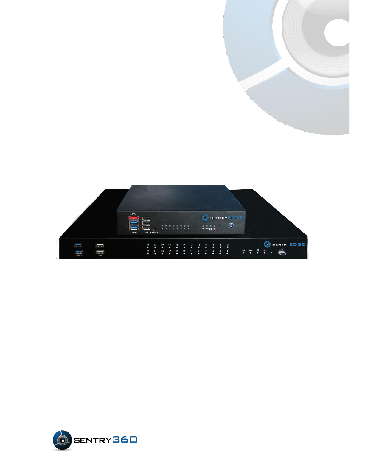
sentryEdge™ NVR
Manual
Ver 1.0
Page 2

2
Page 3

3
Table of Contents
1. 8 Port Mounting ............................................................................................................ 7
2. 16 / 24 Port Mounting ................................................................................................... 9
3. sentryEdge™ Installation Wizard .............................................................................. 11
3.1 Welcome Screen .................................................................................................. 11
3.2 End-user license agreement ................................................................................. 12
3.3 Product registration ............................................................................................... 13
3.4 Select your VMS ................................................................................................... 14
3.5 Selecting additional support documents ................................................................ 15
3.6 Confirm your VMS................................................................................................. 16
3.7 Completing setup .................................................................................................. 17
4. Troubleshooting ......................................................................................................... 18
4.1 Internet Connection Required ............................................................................... 18
4.2 Empty Registration Fields ................................ ..................................................... 18
4.3 Error During Registration ...................................................................................... 19
4.4 Exiting the Installation Wizard Early ...................................................................... 19
4.5 Other Installation Issues........................................................................................ 19
5. Package Contents ...................................................................................................... 21
6. Panel Descriptions ..................................................................................................... 22
6.1 8 Port Front Panel ................................................................................................. 22
6.2 8 Port Rear Panel ................................................................................................. 23
6.3 16/24 Port Front Panel .......................................................................................... 24
6.4 16/24 Port Rear Panel .......................................................................................... 25
7. Connect Devices for Initial Setup ............................................................................. 26
7.1 First Boot and Initial Setup .................................................................................... 26
8. Advanced Network Configuration ............................................................................. 27
8.1 Configure IP Address ................................ ............................................................ 27
8.2 Single Interface ..................................................................................................... 29
Page 4

4
8.3 Dual Interfaces ...................................................................................................... 29
9. System Recovery ...................................................................................................... 30
10. Supported VMS Software ......................................................................................... 32
11. sentryView™ User Manual ....................................................................................... 34
12. System Specifications ............................................................................................ 34
13. Basic Setup ............................................................................................................. 35
13.1 Scanning the network for cameras ........................................................................ 35
13.2 Upgrade a Camera’s Firmware ............................................................................. 35
13.3 Automatically configuring the camera’s IP address ............................................... 38
13.4 Manually configuring a camera’s IP address ......................................................... 39
13.5 Batch configuring multiple cameras ...................................................................... 39
13.6 View a camera’s video through the web browser .................................................. 40
13.7 View a camera’s video through sentryView™ ....................................................... 41
13.8 Restarting a camera with sentryView™ ................................................................. 42
14. Advanced Features (Pro Series Cameras) ............................................................ 43
14.1 Change Camera’s Image Settings ........................................................................ 43
14.2 Change a Camera’s Resolution Settings ............................................................... 44
14.3 Change Camera’s IR/ Auto White Balance Settings .............................................. 44
14.4 Change Camera’s Protocol Settings ..................................................................... 45
14.5 Change Camera’s Multicast Settings .................................................................... 46
14.6 Change Camera’s H.264 Settings ......................................................................... 46
14.7 Change Camera’s Calibration Settings (180 Degree Cameras Only) .................... 47
15. Advanced Features (Mini Series Cameras) ............................................................. 48
15.1 Edit Camera’s Settings ......................................................................................... 48
15.2 Change Camera’s Image Settings ........................................................................ 49
15.3 Change the Camera’s Resolution Settings ............................................................ 50
15.4 Change the Camera’s Bitrate Settings .................................................................. 50
15.5 Change Camera’s Miscellaneous Settings ............................................................ 51
Page 5

5
16. Additional Settings ................................................................................................. 52
16.1 Return Camera to Default Settings ....................................................................... 52
16.2 Reload Camera Settings ....................................................................................... 53
16.3 Change sentryView’s™ Ping Settings ................................................................... 54
16.4 Export Camera Data ............................................................................................. 54
16.4.1 NVR Software ................................................................................................. 55
16.4.2 Excel Spreadsheet ......................................................................................... 55
16.4.3 Text File .......................................................................................................... 56
16.5 Find sentryView™ version number ....................................................................... 57
16.6 Tool Tips ............................................................................................................... 58
17. Contact Information ............................................................................................... 59
Page 6
6
sentryEdge™ NVR
Mounting Guide
Ver 1.0
Page 7
7
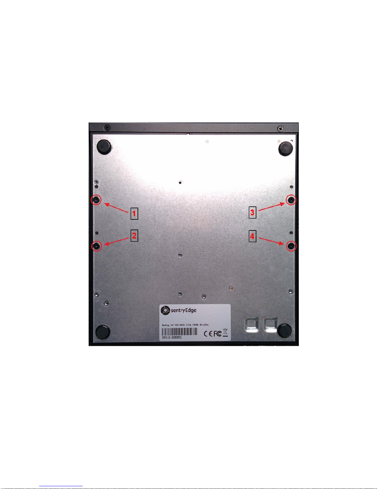
1. 8 Port Mounting
The 8 port sentryEdge™ NVR may be wall or surface mounted using the included hardware.
Please reference the following steps to attach the mounting brackets to the NVR housing.
1. Locate the four mounting screws on the base of the NVR.
Page 8
8
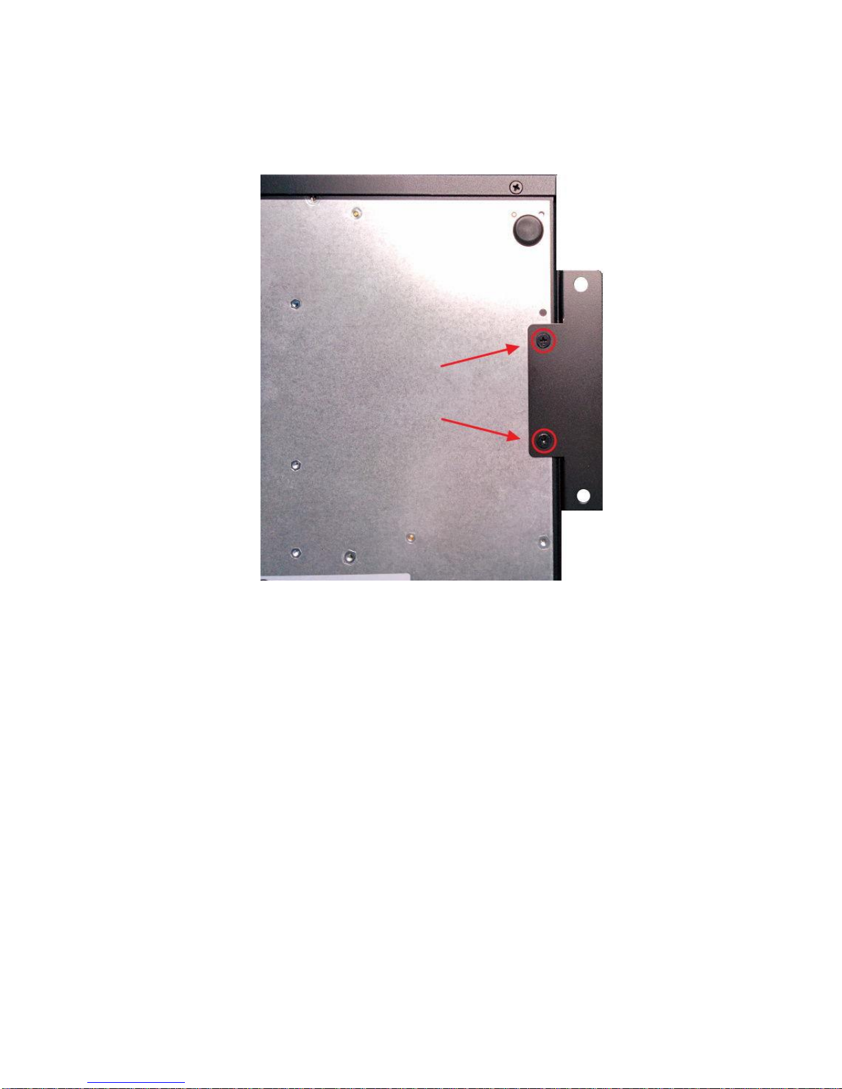
2. Remove the screws, align the mounting bracket, and attach the bracket using the original
screws.
3. Repeat for the other side of the NVR. Use the included wall mount hardware, or hardware
appropriate to the mounting surface, and the open mounting holes on the brackets to
complete mounting the NVR.
Page 9
9
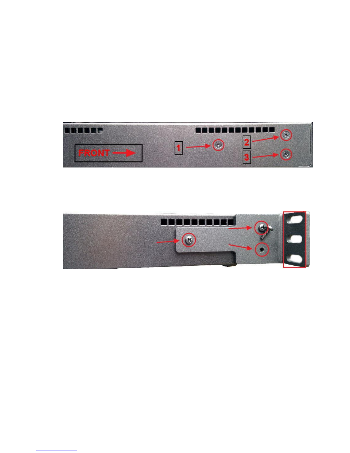
2. 16 / 24 Port Mounting
The 16 / 24 port sentryEdge™ NVR may be rack mounted using the included hardware.
Please reference the following steps to attach the mounting brackets to each side of the NVR
housing.
1. Locate the three screws on one side of the NVR, toward the front of the device.
2. Remove the screws, align the mounting bracket, and attach the bracket using the longer
black screws included with the mounting hardware.
3. Repeat for the other side of the NVR. Use the slotted openings in the brackets to mount
the NVR in the rack unit.
Page 10
10
sentryEdge™ Installation Wizard
User's Manual
Ver 1.0
Page 11
11
3. sentryEdge™ Installation Wizard
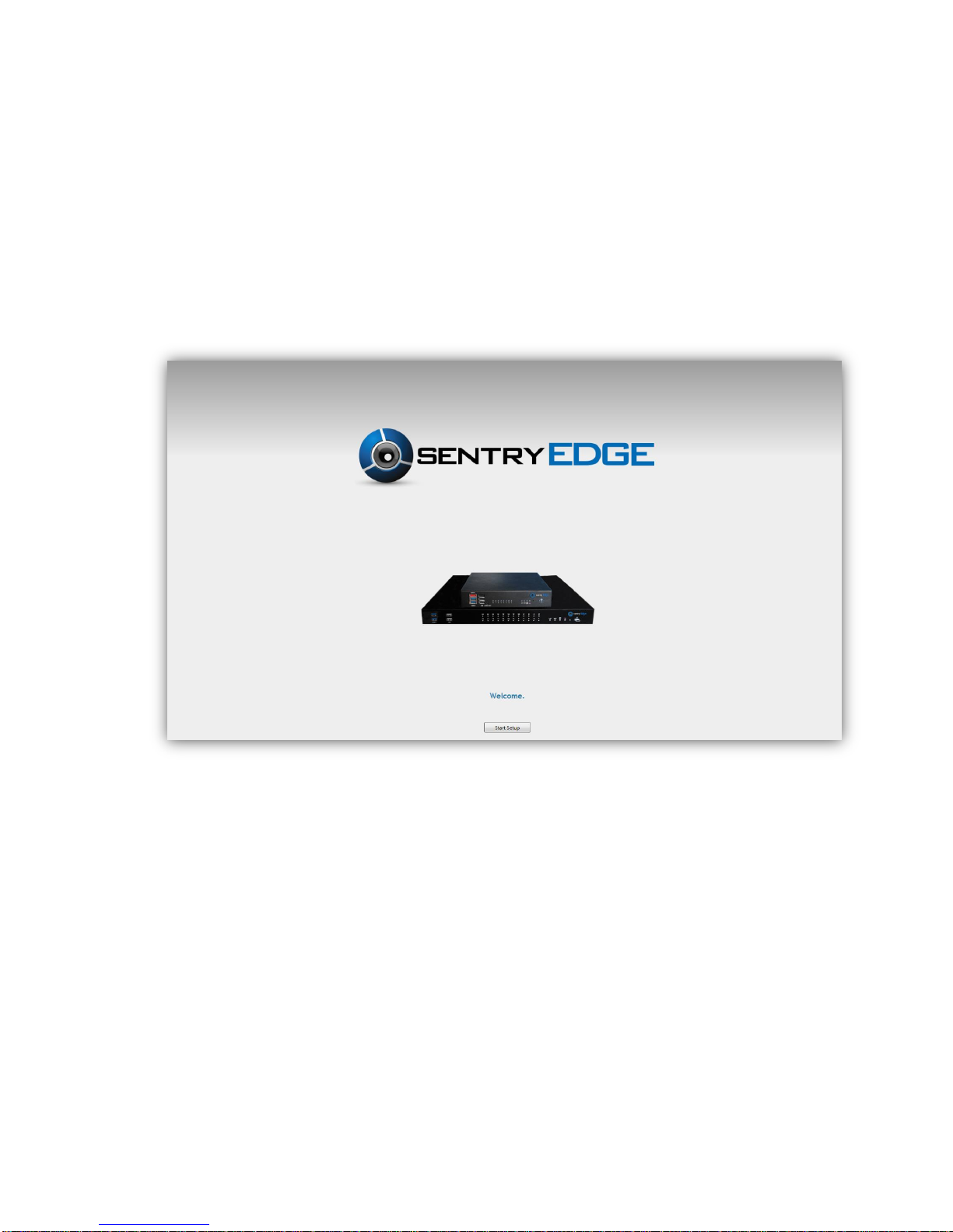
3.1 Welcome Screen
When booting on your sentryEdge™ NVR Server Switch for the first time, you will be taken
through the sentryEdge™ Installation Wizard. Click Start Setup to begin the setup process.
Page 12

12
3.2 End-user license agreement
You will be prompted with an end-user license agreement. You must accept the terms to
continue using the device. Click the check box and click Begin Setup to continue.
Page 13
13
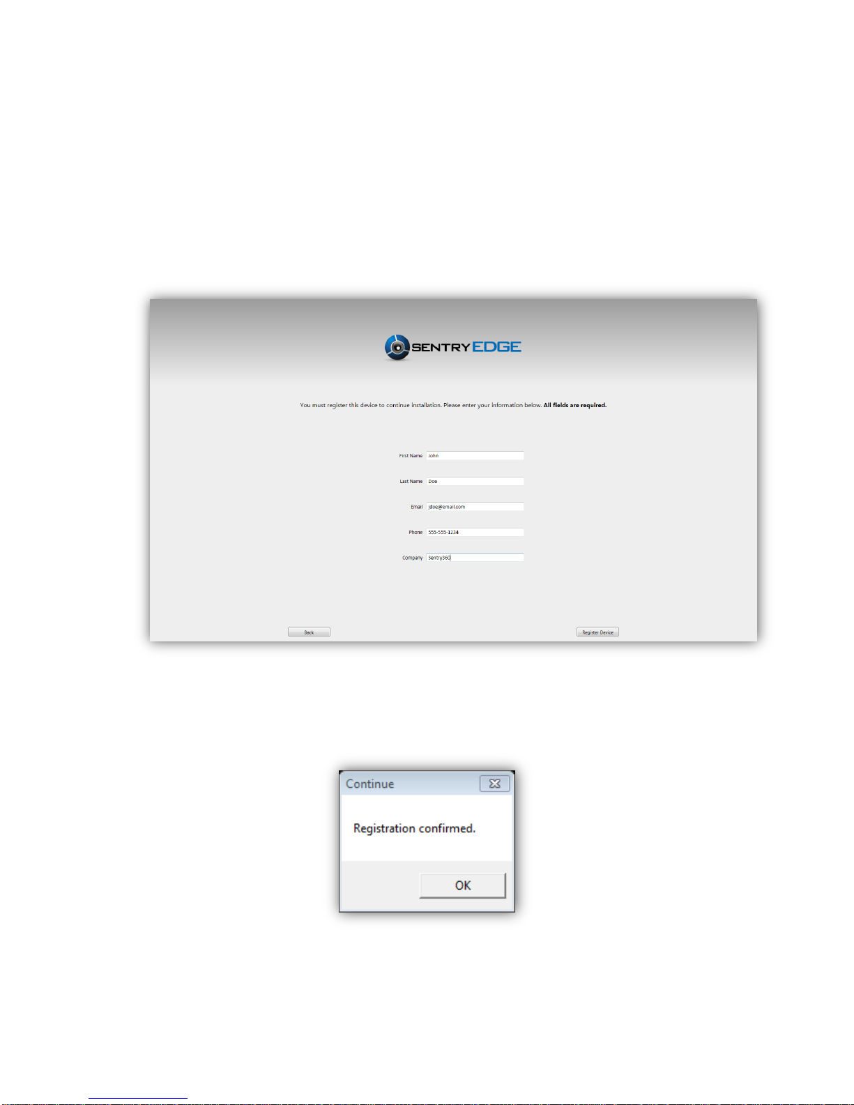
3.3 Product registration
In the available fields, enter your First Name, Last Name, Email Address, Phone Number,
and Company. Click Register Device to submit your information. Note: An internet
connection is required to continue setup.
A dialog box will open to confirm that registration was successful. If any error messages are
received during registration, please refer to section 2. Troubleshooting in this guide.
Page 14

14
3.4 Select your VMS
This screen shows the available supported VMS software platforms compatible with
sentryEdge™. Make your selection by clicking the icon of your preferred VMS. If you are
choosing to use sentryEdge™ by using one of the non-supported VMS platforms, you can
continue without selecting a VMS by clicking Skip this step at the bottom right.
Page 15
15
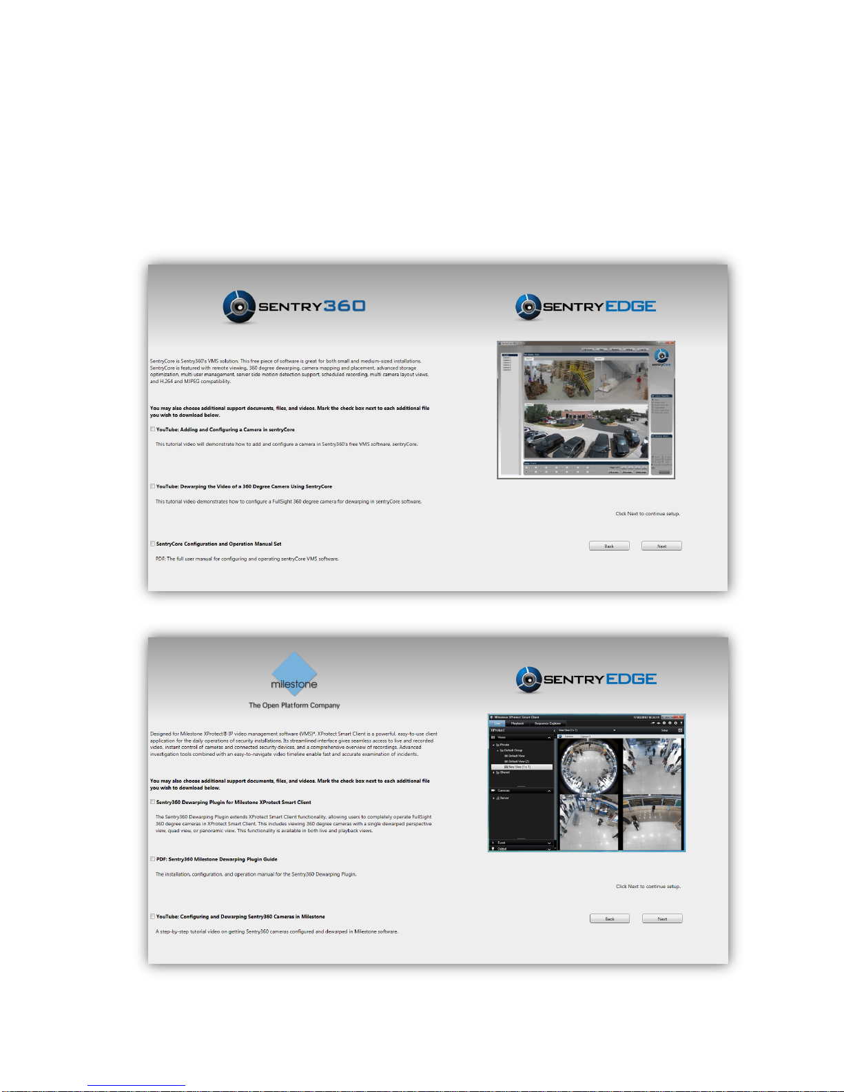
3.5 Selecting additional support documents
You can choose to download additional support documents and files, including user manuals,
plugins, or links to tutorial videos. For each additional file you would like to download, check
the box to the left of each file. When you are finished, click Next to continue. If you would like
to return to the VMS selection screen to choose another platform, click Back.
Page 16
16
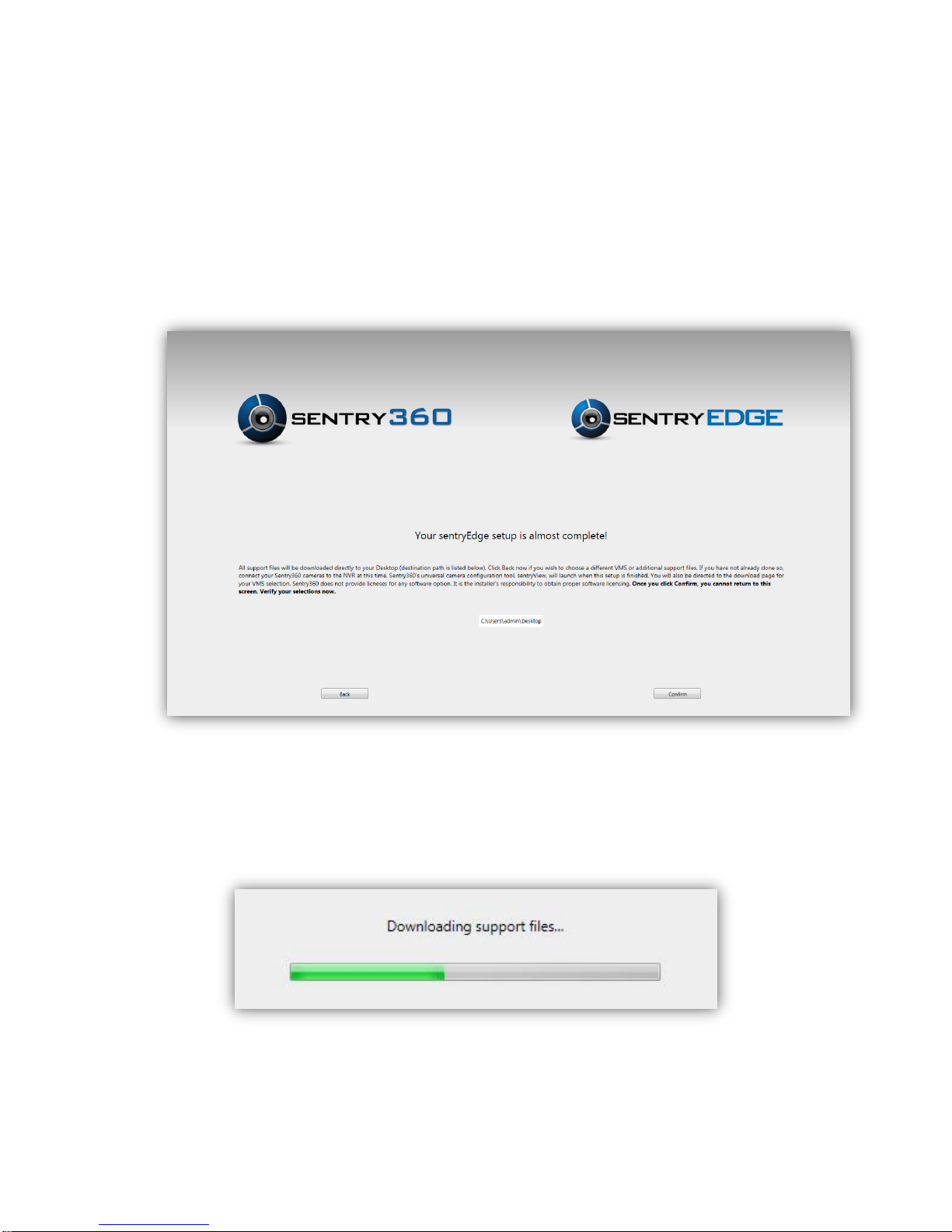
3.6 Confirm your VMS
Confirm all of your choices here. All files will be downloaded directly to the Desktop. The
desktop path will be shown in the middle of the screen. Once all files are downloaded,
sentryView™, Sentry360’s universal camera configuration tool, will launch.
Click Confirm to begin downloading the files. A bar will show download progress.
Page 17

17
3.7 Completing setup
Congratulations! You have finished setting up your sentryEdge™ NVR Server Switch. Click
Finish to exit the sentryEdge™ Installation Wizard and move to the Windows 7 Desktop. You
will find all downloaded support files on your Desktop. Thank you for choosing sentryEdge™!
Page 18
18
4. Troubleshooting
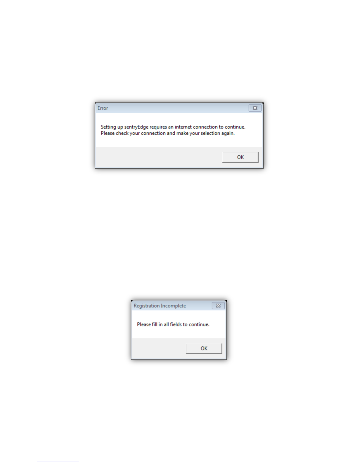
4.1 Internet Connection Required
Running the sentryEdge™ Installation Wizard requires a stable internet connection at all
times in order to complete the registration and download process. If at any time you receive
this error message, check your connections, click OK, and retry the current process. If you
are still unable to continue, see Section 2.4 to exit the Installation Wizard early. Verify your
connections then run the Installation Wizard again.
4.2 Empty Registration Fields
To complete registration, all fields must be correctly filled out. Any blank fields will return the
above error message. Click OK, fill out your First Name, Last Name, Email Address, Phone
Number, and Company to complete registration.
Page 19

19
4.3 Error During Registration
If there are any conflicts when trying to register your sentryEdge™ device, you may receive
an error message similar to the one above. Please call Sentry360 technical support for further
assistance to complete product registration. Have the error code ready when calling.
4.4 Exiting the Installation Wizard Early
If for any reason you need to exit the sentryEdge™ Installation Wizard before completion, you
can do so by pressing Alt and F4 at the same time on the screen. Make sure to have any
error windows closed at this time. You may run the sentryEdge™ Installation Wizard again by
going to the Start menu through the Windows 7 Desktop, clicking All Programs, and
selecting sentryEdge™ Installation Wizard.
4.5 Other Installation Issues
For any other errors while running the sentryEdge™ Installation, please contact Sentry360
technical support immediately.
Page 20

20
sentryEdge™ NVR
User's Manual
Ver 1.0
Page 21

21
5. Package Contents
The sentryEdge™ NVR is packaged and shipped with the following items. Please verify
everything has been enclosed.
sentryEdge™ NVR
Power Adapter
(8 port only)
Power Cord
Documentation
Windows OS DVD
Rack Mount Hardware
Page 22

22
6. Panel Descriptions
6.1 8 Port Front Panel
1
USB 3.0 Ports
The USB 3.0 ports support all 3.0, 2.0 and 1.0 devices. Users can connect
external USB devices, such as a USB mouse, a USB keyboard, a USB
storage device, etc.
2
USB 2.0 Ports
The USB 2.0 ports allow users to connect external USB devices, such as
a USB mouse, a USB keyboard, a USB storage device, etc.
3
Camera LED
The following is a description of the lighted LEDs.
1. Orange: The power is supplied by the camera itself.
2. Green: The power is supplied by the PoE switch at the rear panel.
4
UpLink LED
1. Orange: Network speed is 10/100 Mbps.
2. Green: Network speed is 1000 Mbps.
5
WAN LED
6
HDD LED
1. Blink: The HDD/CF Card is running.
2. OFF: No storage device is found.
7
PoE LED
The PoE LED will start to blink when the output power is reaching its limit.
8
Reset Switch
Insert a pin to force restart the system.
9
Power Key
1. Blue: The system is on. The power key will not respond while the
system is running.
2. Green: They system is shutdown but PoE switch is still alive. Press the
power key to startup the system.
3. OFF: The power cord is disconnected.
Page 23

23
6.2 8 Port Rear Panel
1
Power Jack
Connect the power cord and the power adaptor shipped with the
NVR. Use of another power supply may cause overloading.
2
PoE Switch
The PoE switch provides connection to IP cameras.
3
WAN – RJ-45
This port is for network connection to the internet.
4
UpLink – RJ-45
This is for connection to a router or switch within the NVR’s private
network. The RJ-45 port will not function when the SFP port is
connected.
5
UpLink – SFP
Users can connect a SFP module that expands the NVR’s private
network connection by fiber ports. This port has absolute priority over
the RJ-45 port for uplink, and they will not function simultaneously.
6
RS232
This port provides connection to a RS232 device. Users can control
camera PTZ functions, connect to access control systems, or receive
data from additional sensors.
7
e-SATA
Users can connect an e-SATA storage device via this port.
8
HDMI Monitor
An HDMI connector is provided for connection to a HDMI monitor.
9
VGA Monitor
The VGA output connector is offered for connection to a VGA monitor.
10
Audio Out
An audio out connector is provided to output sounds.
Page 24

24
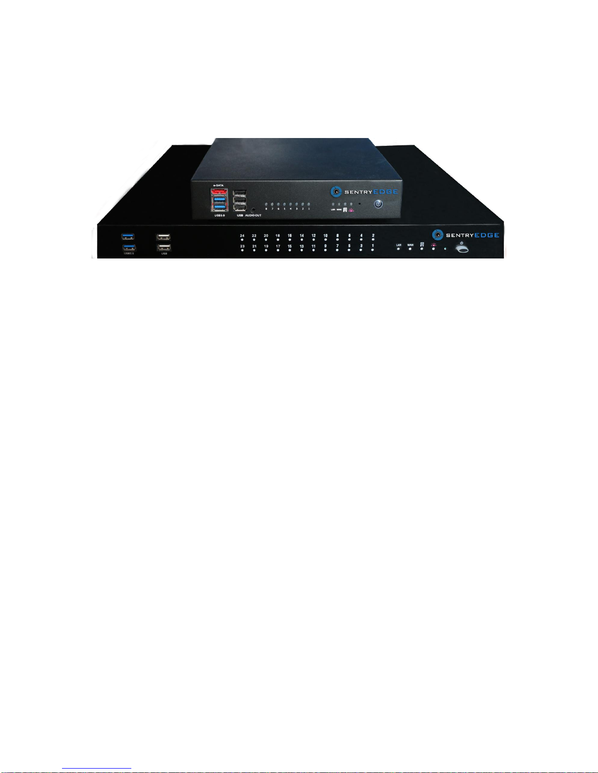
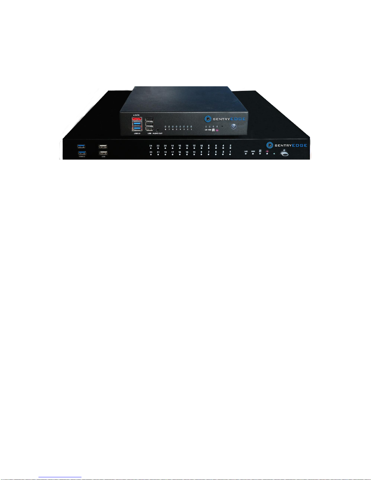
6.3 16/24 Port Front Panel
1
USB 3.0 Ports
The USB 3.0 ports support all 3.0, 2.0 and 1.0 devices. Users can connect
external USB devices, such as a USB mouse, a USB keyboard, a USB
storage device, etc.
2
USB 2.0 Ports
The USB 2.0 ports allow users to connect external USB devices, such as
a USB mouse, a USB keyboard, a USB storage device, etc.
3
Camera LED
The following is description of the lighted LEDs.
1. Orange: The power is supplied by the camera itself.
2. Green: The power is supplied by the PoE switch at the rear panel.
4
UpLink LED
1. Orange: Network speed is 10/100 Mbps.
2. Green: Network speed is 1000 Mbps.
5
WAN LED
6
HDD LED
1. Blink: The HDD is running.
2. OFF: No storage device is found.
7
PoE LED
The PoE LED will start to blink when the output power is reaching its limit.
8
Reset Switch
Insert a pin to force restart the system.
9
Power Key
1. Blue: The system is on. The power key will not respond while the
system is running.
2. Green: They system is shutdown but PoE switch is still alive. Press the
power key to startup the system.
3. OFF: The power cord is disconnected.
1 2 3
4 5 6 7 8 9
Page 25

25
6.4 16/24 Port Rear Panel
1
Power Jack
Connect the power supply cord shipped with the NVR. Use of other
power supply cords may cause overloading.
2
PoE Switch
The PoE switch provides connection to IP cameras. With different
models of NVR, the number of PoE switch is also different.
3
UpLink – RJ-45
This is for connection to a router or switch within the NVR’s private
network. The RJ-45 port will not function when the SFP port is
connected.
4
RS232
This port provides connection to a RS232 device. Users can control
camera PTZ functions, connect to access control systems, or receive
data from additional sensors.
5
UpLink – SFP
Users can connect a SFP module that expands the NVR’s private
network connection by fiber ports. This port has absolute priority over
the RJ-45 port for uplink, and they will not function simultaneously.
6
USB 2.0 Ports
The USB 2.0 ports allow users to connect external USB devices, such
as a USB mouse, a USB keyboard, a USB storage device, etc.
7
WAN – RJ-45
This port is for network connection to the internet.
8
e-SATA
Users can connect an e-SATA storage device via this port.
9
HDMI Monitor
An HDMI connector is provided for connection to an HDMI monitor.
10
VGA Monitor
The VGA output connector is offered for connection to a VGA monitor.
11
Audio Out
An audio out connector is provided to output sound.
Page 26

26
7. Connect Devices for Initial Setup
Please connect at a minimum the following devices to the sentryEdge™ NVR. Please note
that an active DHCP enabled internet connection is required for initial setup.
USB Mouse and Keyboard
Display Monitor (VGA or HDMI)
Active Internet (DHCP enabled connection to the LAN Uplink port)
Connect the power cord to the NVR and the device will automatically boot. When presented
with the Windows Login Screen please enter the following default credentials:
User Name
Password
admin
admin
7.1 First Boot and Initial Setup
This first time the sentryEdge™ NVR boots, the sentryEdge™ Installation Wizard will
automatically start.
Page 27

27
The installation wizard will guide the user through registering the device, choosing a VMS
platform, and downloading additional support files. Please see the sentryEdge™
Installation Wizard Guide, included separately in this packaging, for a step by step
walkthrough of the application.
Once the installation wizard is completed, the user may continue to configure the network
with more advanced options in the next section, such as configuring a static IP address.
8. Advanced Network Configuration
The sentryEdge™ NVR can be configured on a single network interface, or dual interfaces.
8.1 Configure IP Address
To configure the IP address settings for a network adapter, follow the steps below.
1. Right-click on the desired adapter and select Properties.
Page 28

28
2. Highlight Internet Protocol Version 4 (TCP/IPv4) and click the Properties button.
3. Enter the appropriate IP address, Subnet mask, Default gateway, and DNS server
information for the network. If this information is not known, contact the network
administrator. Click OK.
Page 29

29
8.2 Single Interface
Use the single interface configuration if the sentryEdge™ NVR is connected to only one
network, and it is the same network to which the IP cameras are connected.
1. Connect the active LAN network to the LAN Uplink port (see the Rear Panel diagram
above for the specific model).
2. If the LAN has a DHCP server the user can choose to leave the adapter to configure itself
automatically (this may require a system reboot with the cable connected). If not, or if a
static IP address is preferred, configure the LAN Uplink adapter with the appropriate static
IP address information. The LAN adapter is the Intel® 82579LM Gigabit adapter under
the Windows Network Connections settings. If the user is unsure which configuration to
use, please contact the network administrator.
NOTE: The LAN Uplink adapter MUST be assigned a static IP address (see section 4.1
above) in the same range as the IP cameras under any of the following circumstances:
The LAN Uplink port is not used, for example if the NVR is standalone and not
connected to another network.
The LAN to which the Uplink port is connected does not have a DHCP server.
A static IP address is desired for the NVR on the connected network.
8.3 Dual Interfaces
Use the dual interface configuration if the sentryEdge™ NVR is connected to two networks on
different subnets: one private network for the cameras (LAN Uplink), and one public network
for other network resources or internet connectivity (WAN Uplink).
1. Follow the instructions above for the Single Interface to connect and configure the LAN
Uplink.
2. Connect the active WAN network to the WAN Uplink port (see the Rear Panel diagram
above for the specific model).
3. If the WAN has a DHCP server the user can choose to leave the adapter to configure
itself automatically. If not, or if a static IP address is preferred, configure the WAN Uplink
adapter with the appropriate static IP address information. The WAN adapter is the
Realtek PCIe GBE adapter under the Windows Network Connections settings. If the user
is unsure which configuration to use, please contact the network administrator.
Page 30

30
9. System Recovery
If the user wishes to restore the sentryEdge™ NVR to a factory default state, please use the
following procedure. In the event there is a hardware failure and the internal hard drive is
unusable, please contact Sentry360 support.
Things you will need:
USB Mouse and Keyboard
USB Storage media with downloaded recovery files
1. You will need to download the sentryEdge recovery file hosted on the Sentry360 Partner
Portal: http://sentry360.com/Partner/sentryedge.php (NOTE: You will need to register to
access our partner portal by visiting this link:
http://sentry360.com/Partner/login.html#toregister )
2. Power off the system and disconnect the power cable.
3. Attach the USB Mouse and Keyboard to the USB 3.0 ports (see section 2).
4. Attach the USB storage media with the recovery files to one of the USB 2.0 ports (see
section 2).
5. Power on the system by plugging the power cable back in.
6. Press F8 on the keyboard repeatedly (or press and hold F8) to enter the Windows
Advanced Boot Options menu. Select Repair Your Computer and press Enter.
** If the user is unable to enter the Advance Boot Options menu, retry from Step 2, but
connect the USB Mouse and Keyboard to the USB 2.0 ports.
7. The System Recovery Options dialog will appear in a few moments. If the USB Mouse
and Keyboard are not functioning, connect them to the USB 2.0 ports. Click Next.
8. The next dialog prompts for the user name and password of the Administrator account.
The default credentials are:
Page 31

31
User Name
Password
admin
admin
Click OK.
9. In the next dialog click System Image Recovery. Windows will scan for available images
and select the most recent image. Click Next.
** If the user has created additional recovery images, these may be selected by choosing
Select a system image, clicking Next, and selecting another image on the next page.
10. In the Choose additional restore options dialog, leave the default options and click
Next.
11. The next dialog confirms the image selection, click Finish. A warning dialog will appear
explaining that all data on the target drives will be erased, click Yes to start the restore
process.
Page 32

32
12. A progress window will track the restore process, and the computer will restart when it is
complete. The sentryEdge™ NVR is now restored to a factory state.
10. Supported VMS Software
The following VMS software has been certified at the tested version and below to be
compatible with the sentryEdge™ NVR.
Sentry360 sentryCore™ Server 2.0.2.7
Arteco Logic NEXT 4.0
AxxonSoft Axxon Next 3.5
exacq exacqVision Pro 5.10
Genetec Security Center 5.2
Milestone xProtect Corporate 2013 R2 / Expert 2013 R2 / Enterprise 2013 8.5e /
Professional 2013 8.5e / Express 2013 1.5e / Essential 2013 2.5e / Go 2013 2.5e/ Arcus
OnSSI Ocularis PS / IS / CS 3.7
Video Insight Monitor Station 5.5
NOTE: It is the responsibility of the end user or system integrator to obtain proper software
and channel licenses for any 3rd party software provider.
Page 33

33
sentryView™ Camera Configuration Tool
User Manual
Rev. 6/30/2014
Page 34

34
11. sentryView™ User Manual
What is sentryView™?
SentryView™ is the industry’s first plug-and-play tool for IP video. You can configure up to
250 cameras at a time. Advanced feature sets include exporting straight to VMS, batch
firmware, batch hardware, batch video settings, batch motion detection setup, and more. With
this tool you can fully configure a 250 camera deployment in less than 5 minutes. This search
software tool will increase productivity in the field, making its use a necessity for anyone
installing Sentry360 cameras.
12. System Specifications
Current Version: 3.2.3.5
Supported Operating Systems: Windows Vista, Windows 7, Windows Server 2008,
Windows 8.
Our software can run natively on both x86 and x64 systems. There are currently no Mac OS
X or Linux versions available.
Page 35

35
13. Basic Setup
13.1 Scanning the network for cameras
Make sure all Sentry360 cameras are connected correctly to your network. Click Scan at the
top left of the program (Alternatively, click on Tools > Scan). This will search your network for
all connected devices. Once the scan is complete, sentryView™ will list the camera’s Model,
MAC Address, IP Address, and other network information in the main window.
13.2 Upgrade a Camera’s Firmware
Right click on the camera that you would like to upgrade the firmware of and select Upgrade
Firmware from the list (Alternatively you can select the camera from the list and click on
Tools > Upgrade Firmware).
Page 36

36
The Firmware Upgrade window will open up. Click Browse to choose a firmware file already
downloaded on your computer.
Navigate to the location where the firmware file is saved on your computer and click Open.
(Note: you can find download links to our firmware by visiting our Partner Portal at
http://sentry360.com/Partner/firmware.php )
Page 37

37
(Note: For Mini Series cameras you want to select the “uImage_userland” file in the firmware
folder.)
SentryView™ will ask you to confirm that you want to upload the new firmware. Click Upload.
The firmware will then be uploaded to the camera and the camera will reboot.
To confirm the firmware has been upgraded, check the number under the Firmware column
for the camera. (Note: If the camera still shows the same firmware version after scanning, it
may require a power cycle. Unplug the camera for 30 seconds, and then reconnect it.)
Page 38

38
13.3 Automatically configuring the camera’s IP
address
Select the camera you would like to configure. Click the Auto Configure button at the top
(Alternatively right click the camera on the list and choose Auto Configure Camera).
If there are multiple network cards installed, choose the correct adapter that you want your
camera to be configured for. Confirm that these network settings are correct. If you need to
manually specify any settings, choose the Custom option for IP Scheme, Subnet, or
Gateway, and enter the information, then click Configure.
Unless specified otherwise, sentryView™ will automatically assign the camera the next
available IP address on that scheme. When complete, a dialog box will confirm your camera’s
new settings. SentryView™ will then rescan the network.
Page 39

39
13.4 Manually configuring a camera’s IP address
Select the camera you would like to configure. In the Network tab at the bottom, enter the
new IP Address, Subnet Mask, and Gateway. If using a DHCP server, check the DHCP box.
When the information is entered, click Save. SentryView™ will configure the camera’s new
settings and rescan the network.
13.5 Batch configuring multiple cameras
To automatically configure multiple cameras, select each camera you want to configure by
selecting each with a check mark in the left column. When all cameras are selected, you can
configure all of them by following Step C (Automatically configuring the camera’s IP
address) as listed above.
Page 40

40
13.6 View a camera’s video through the web
browser
Right click on a camera and choose Browse (Alternatively select a camera and click on
Tools > Browse). This will open the camera in Internet Explorer. (Note: If opening a Mini
Series camera, you will be prompted for a username and password. Unless configured
otherwise, the default name will be “Admin” and the password “1234”) Consult your camera’s
manual for further information on using the web interface.
Page 41

41
13.7 View a camera’s video through sentryView™
Right click on the camera and select View Video (Alternatively select a camera and click
Tools > View Video).
SentryView™ will open up a new window that shows the live video of the camera. (Note: The
camera’s MJPEG stream must be enabled for Video Preview). The window supports basic
digital PTZ functionality using the mouse buttons and scroll wheel.
Page 42

42
13.8 Restarting a camera with sentryView™
Right click on a camera and select Restart Camera (Alternatively select a camera and click
Tools > Restart Camera).
SentryView™ will send a restart signal to the camera and display a window confirming that
the restart request has been sent. The camera may take up to a few minutes to reconnect.
Page 43

43
14. Advanced Features (Pro Series Cameras)
14.1 Change Camera’s Image Settings
Select the Pro Series camera you wish to change the image settings of and then click on the
Image tab. In this tab you can adjust the camera’s MJPEG Quality, Sharpness, Saturation,
Contrast, Auto-Exposure Priority Mode, Shutter Speed, and Brightness.
When you are finished changing the camera’s settings, click Save.
Page 44

44
14.2 Change a Camera’s Resolution Settings
Select the camera you wish to change the Resolution settings of and then click on the
Resolution tab. In this tab you can adjust the camera’s Resolution, Scaling, Denominator,
Frame Rate, Bit Rate, Vertical Image Flip, and Horizontal Image Flip.
When you are finished changing the camera’s settings, click Save.
14.3 Change Camera’s IR/ Auto White Balance
Settings
Select the camera you wish to change the IR/White Balance of and then click on the IR/AWB
tab. In this tab you can adjust the camera’s IR mode, Threshold, Ratio, AWB Mode, Red to
Green Ratio, and Blue to Green Ratio.
Page 45

45
When you are finished changing the camera’s settings, click Save.
14.4 Change Camera’s Protocol Settings
Select the camera you wish to change the Protocol settings of and then click on the
Protocols tab. In this tab you can adjust the camera’s TCP Port, UDP Port, RTSP Port, TCP
Timeout, UDP Timeout, and RTSP Timeout.
Page 46

46
When you are finished changing the camera’s settings, click Save.
14.5 Change Camera’s Multicast Settings
Select the camera you wish to change the Multicast settings of and then click on the
Multicast tab. In this tab you can adjust the camera’s Multicast Mode, Multicast IP
Address, and Multicast Port.
When you are finished changing the camera’s settings, click Save.
14.6 Change Camera’s H.264 Settings
Select the camera you wish to change the H.264 settings of and then click on the H.264 tab.
In this tab you can adjust the camera’s H.264 Mode, Frame Limit, H.264 Quality, and
Threshold.
Page 47

47
When you are finished changing the camera’s settings, click Save.
14.7 Change Camera’s Calibration Settings (180
Degree Cameras Only)
Select the camera you wish to change the Calibration settings of and then click on the
Calibration tab. To correctly calibration an FS-IP8180 camera, click Load Calibration
Window to bring up a video preview of the camera. Click Reset Calibration Settings to
re-center the view of the camera. Once centered, click the Up, Down, Left, and Right arrow
buttons to shift the view in that direction.
Page 48

48
When the view is properly calibrated, click Save.
15. Advanced Features (Mini Series Cameras)
Applies to FS-IP3000-M, FS-IP5000-M, FS-IP4180, IS-DM200-IR, IS-DM220, IS-DM220-HB,
IS-DM220-IR, IS-DM320-HB, IS-DM320-IR, IS-DM520-HB, IS-DM520-IR, IS-DM240, IS-DM240-V,
IS-DM260, IS-DM260-R, IS-IP200-DN, IS-IP290, IS-IP200-IRB, and IS-IP220-IRB-30 camera models.
Please consult your camera’s manual for further detailed information on each of the settings listed
below.
15.1 Edit Camera’s Settings
In order to view or edit the settings of a Sentry360 Mini Series Camera, first click Edit
Camera Settings in the Network tab. The camera’s settings will not be accessible until this
button is clicked.
Page 49

49
15.2 Change Camera’s Image Settings
Select the camera you wish to change the Image settings of and then click on the Image tab.
In this tab you can adjust the camera’s Brightness, Sharpness, Saturation, Contrast, Hue,
WDR, and Rotation Settings.
When you are finished changing the camera’s settings, click Save.
Page 50

50
15.3 Change the Camera’s Resolution Settings
Select the camera you wish to change the resolution settings of and then click on the
Resolution tab. In this tab you can adjust the camera’s compression format and resolution
settings.
When you are finished changing the camera’s settings, click Save.
15.4 Change the Camera’s Bitrate Settings
Select the FullSight/InSight camera you wish to change the Bitrate settings of and click on the
Bitrate tab. In this tab you can adjust the camera’s bitrate settings.
Page 51

51
When you are finished changing the camera’s settings, click Save.
15.5 Change Camera’s Miscellaneous Settings
Select the FullSight/InSight Camera that you would like to change the miscellaneous settings
of and click on the Misc tab. In this tab you can adjust the camera’s Primary DNS,
Secondary DNS, TCP Port, RTSP Port settings, and toggle the display of date and time on
or off.
Page 52

52
When you are finished changing the camera’s settings, click Save.
16. Additional Settings
16.1 Return Camera to Default Settings
From the Network tab, click the Default button for the selected camera. This will return the
camera’s image settings to factory default. After clicking Default, you will be prompted to
confirm this choice before continuing. Click Yes to continue to return camera to default
settings. The camera may take several seconds before it is back online. Note: When clicking
Default for a Sentry360 Pro Series camera, this will also change the Gateway to 0.0.0.0. IP
address and Subnet are not affected.
Page 53

53
16.2 Reload Camera Settings
From the Network tab, click the Reload button. This will refresh all of the selected camera’s
values in sentryView™.
Page 54

54
16.3 Change sentryView’s™ Ping Settings
Click File > Settings to open sentryView’s™ Ping settings. In this new window you can
adjust Ping settings, Mini Series camera auto login settings, and Pro series communication
type
Adjust the settings in this window, and click Save when you are complete.
16.4 Export Camera Data
SentryView™ allows the user to export camera information in multiple formats, including
Excel spreadsheets, text files, and even direct-to-VMS.
Page 55

55
16.4.1 NVR Software
SentryView™ has the ability to export camera configurations to sentryCore™ and Video
Insight. In order to use this feature click on Export > NVR. Choose either sentryCore™ or
Video Insight from the dropdown. Select the camera(s) that you want to export from the list
and set a display name for the cameras in the NVR Display Name column. Click Export.
SentryCore™ will add these cameras into the NVR software that you have selected. Launch
the NVR software to confirm that the cameras have been added.
16.4.2 Excel Spreadsheet
SentryView™ supports exporting camera data to an Excel spreadsheet. In order to use this
feature select the camera(s) that you would like to export data for.
Page 56

56
Click on Export > Excel and specify the path and name for the spreadsheet then click Save.
SentryView™ will create the spreadsheet in the destination you specified.
16.4.3 Text File
SentryView™ supports exporting camera data to text files. In order to use this feature select
the camera(s) that you would like to export data for.
Page 57

57
Click on Export > Text and specify the path and name for the text file then click Save.
SentryView™ will create the text file in the destination you specified.
16.5 Find sentryView™ version number
In order to show the version of sentryView™ click on Help > About sentryView™.
SentryView™ will open a new window displaying the version number.
Page 58

58
16.6 Tool Tips
SentryView™ will display the explanation of a camera setting using tool tips. Using the
mouse, hover the pointer over the desired setting’s name. A small text box will appear after a
few seconds explaining that setting.
Page 59

59
17. Contact Information
For support, please contact Sentry360:
Website: http://www.sentry360.com
Email: support@sentry360.com
Toll Free: 1-800-261-2707
Direct: 1-630-355-3440
Page 60

60
23807 West Andrew Road Suite B Plainfield, IL 60585 | (800) 261-2707 | www.sentry360.com
 Loading...