

Sentry360 IS-IP200-IRB,220-IRB-30 User Manual

IS-IP200-IRB, 220-IRB-30
User Manual
Ver 1.0
©Sentry360 2014

Table of Contents
1. Overview ............................................................................................................................ 3
1.1 Features ...................................................................................................................... 3
1.2 Package Contents........................................................................................................ 4
1.3 Dimensions .................................................................................................................. 5
1.4 Connectors .................................................................................................................. 6
2. Camera Cabling ................................................................................................................. 8
2.1 Connect Power ............................................................................................................ 8
2.2 Connect Ethernet Cable ............................................................................................... 8
2.3 Connect Alarm I/O........................................................................................................ 8
3. Installation ......................................................................................................................... 9
3.1 Ceiling / Wall Mounting ................................................................................................ 9
4. System Requirements .....................................................................................................11
5. Access Camera ................................................................................................................12
6. Configure Video Streams ................................................................................................16
7. Configuration Files Export / Import ................................................................................17
Appendix A: Delete the Existing DC Viewer ..........................................................................18
Appendix B: Setup Internet Security .....................................................................................19

1. Overview
The IS-IP200-IRB camera is a Quad-streaming, H.264 & MJPEG encoding, 2.0 Megapixel
resolution, IP-addressable, network camera. It is designed to deliver full-motion, high-definition,
progressive scan digital video across local area networks. The IS-IP200-IRB features a design
with no moving parts, a 1/2.7” CMOS sensor, Power over Ethernet, 23 built-in IR-LEDs, and
Audio-In/Audio-Out. The IS-IP200-IRB is a cost effective, high-level, megapixel network camera.
1.1 Features
• Progressive Scan CMOS Sensor
• Quad Streams support
• Dual Streams, Full HD 1080P real-time + D1 real-time
• Quad Streams Compression:
H.264 Baseline / Main / High Profile + MJPEG
• Multi-language support
• Tampering Alarm
• Wide Dynamic Range
• Remote Zoom & Focus (Motorized Lens)
• Motion Detection
• Privacy Masks
• Smart Picture Quality / 3D Noise Reduction
• Vertical View Mode (Image rotation by 90 derees)
• Smart IR Mode
• Network Failure Detection
• Day/Night (ICR)
• IR LED Module (working distance up to 25m)
• Micro SD support
• Weatherproof (IP66 International)
• Sunshield
• Integrated Mounting Bracket with Cable Management
• ONVIF Support
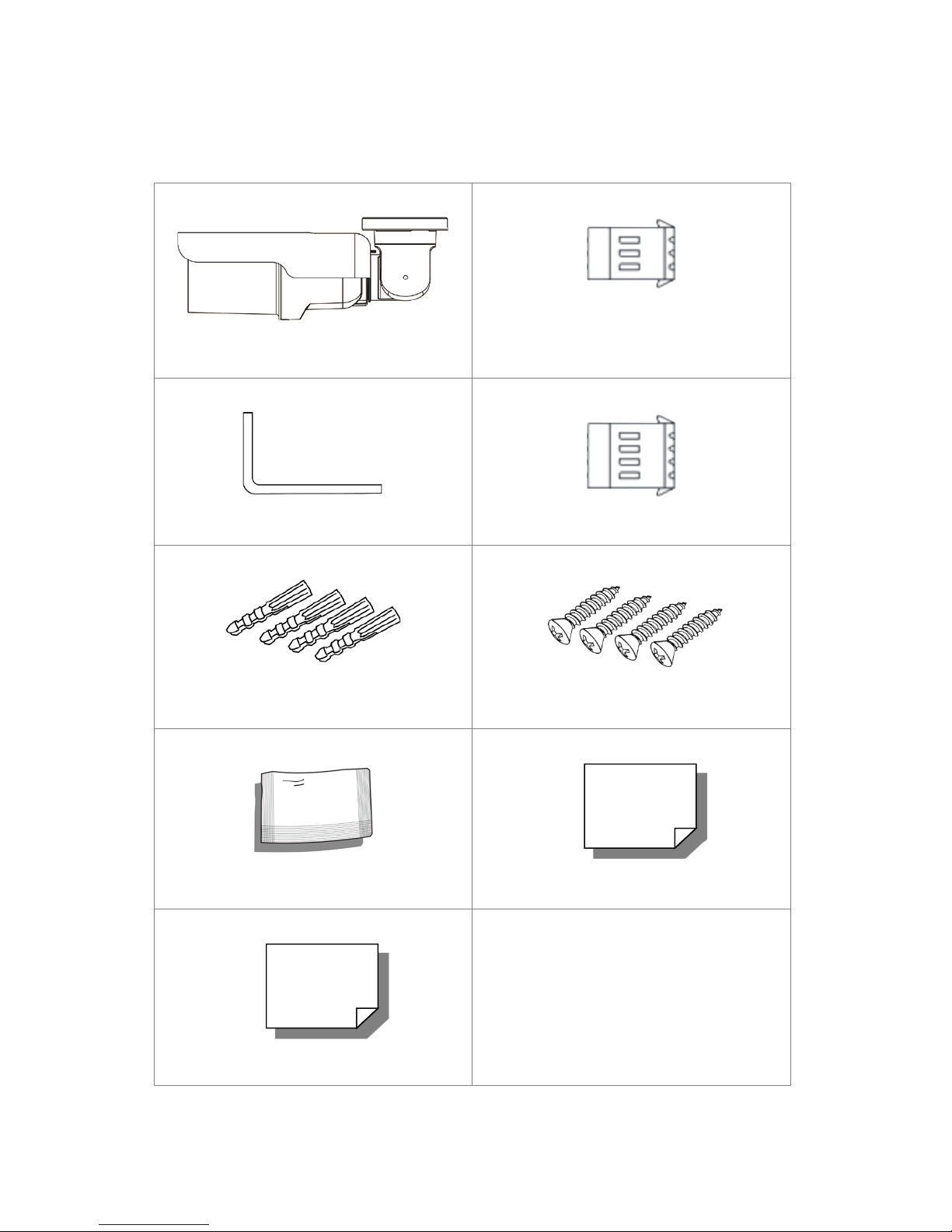
1.2 Package Contents
Please check the package contains the following items listed below.
Camera (Cable included)
M4 Inner Hex Wrench (x1)
Plastic Screw Anchors (×5)
Power Terminal Block (x1)
Alarm Terminal Block (x1)
M4 Self Tapping Screws (×5)
Desiccant
Quick Guide
Desiccant User Guide
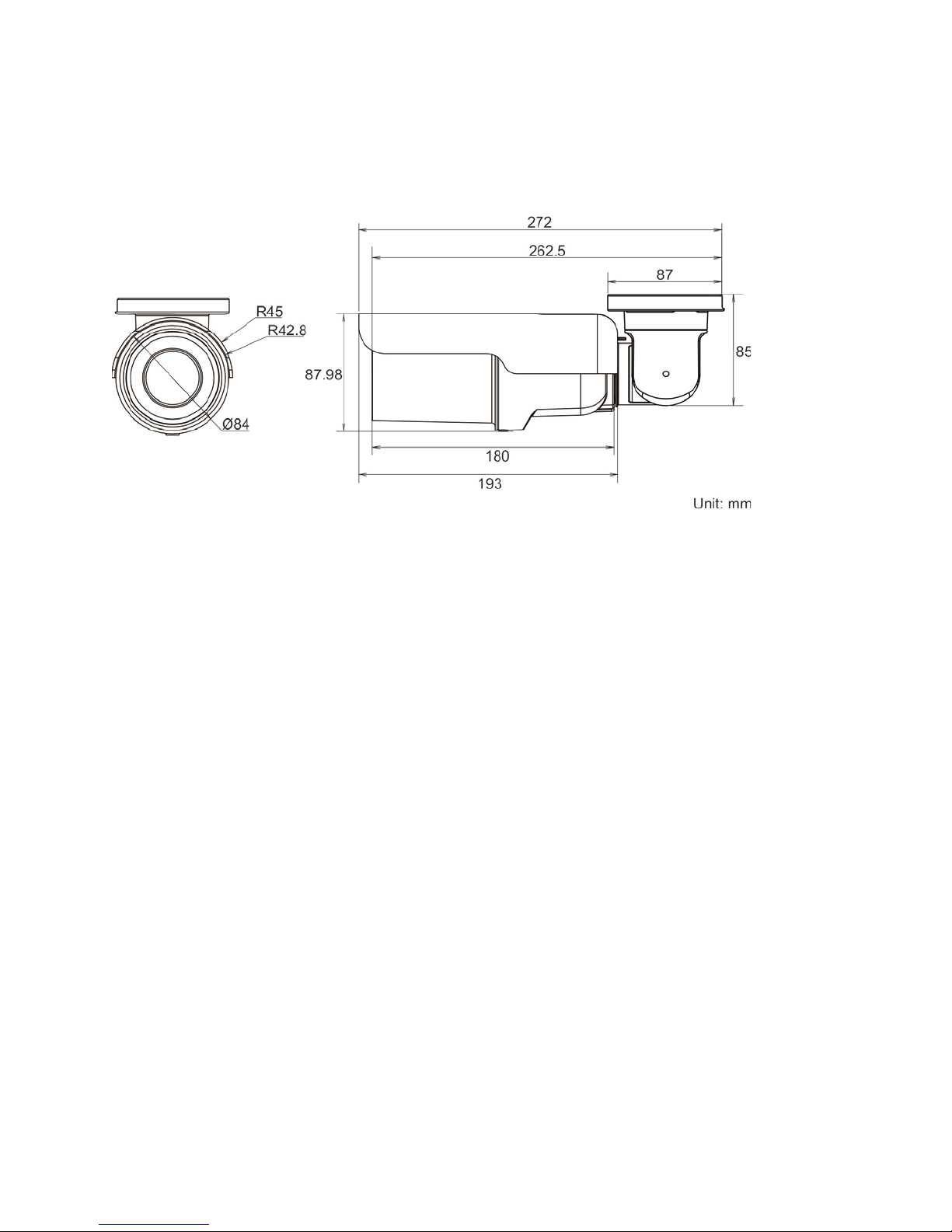
1.3 Dimensions
The IS-IP200-IRB dimensions are shown below.

1.4 Connectors
No
Cable
Pin
Definition
Remarks
1
Network (with PoE)
-
RJ-45 connector with LED
1
AC 24V-1
DC (-)
2
GND
Reserved
3
AC 24V-2
DC (+)
1
ALM_DI-
2
ALM_DI+
3
ALM_DO-
4
ALM_DO+
Pink
Line In/ Mic In
Two-way audio
transmission
Green
Line Out
5
BNC
-
Analog Video Output
The diagram below shows the IS-IP200-IRB reset button and various connectors. Definition for
each connector will be given as follows.
All-in-one Cable
2
(3-pin Terminal Block)
3
(4-pin Terminal Block)
4 Audio I/O
Power
Alarm
Power connection
Alarm connection
 Loading...