

Page 1

IS-IP200-DN
User Manual
Ver 1.0
©Sentry360 2014
Page 2

Table of Contents
1. Overview ............................................................................................................................ 3
1.1 Features ...................................................................................................................... 3
1.2 Package Contents........................................................................................................ 4
1.3 Dimensions .................................................................................................................. 4
1.4 Connectors .................................................................................................................. 5
2. Camera Cabling ................................................................................................................. 6
2.1 Connect Power ............................................................................................................ 6
2.2 Connect Ethernet Cable ............................................................................................... 6
2.3 Lens Mounting ............................................................................................................. 6
2.4 Connect Alarm I/O ....................................................................................................... 7
3. System Requirements ...................................................................................................... 7
4. Access Camera ................................................................................................................. 8
5. Configure Video Streams ................................................................................................12
6. Configuration Files Export / Import ................................................................................13
Appendix A: Delete the Existing DC Viewer ..........................................................................14
Appendix B: Setup Internet Security .....................................................................................15
Appendix C: Back Focus Adjustment....................................................................................16
Page 3

1. Overview
The IS-IP200-DN camera is a Quad-streaming, H.264 & MJPEG encoding, 2.0 Megapixel
resolution, IP-addressable network camera. It is designed to deliver full-motion, high-definition,
progressive scan digital video across local area networks. The IS-IP200-DN features a design
with no moving parts, a 1/2.7” CMOS sensor, Power over Ethernet, and Audio-In/Audio-Out. The
IS-IP200-DN is a high-level, cost effective megapixel network camera.
1.1 Features
• Progressive Scan CMOS Sensor
• C / CS Mount Lens
• Quad Streams support
• Dual Streams, Full HD 1080P real-time + D1 real-time
• Dual Streams Compression- H.264 Baseline / Main / High Profile + MJPEG
• Multi-language support
• Tampering Alarm
• Wide Dynamic Range
• Motion Detection
• Privacy Masks
• Smart Picture Quality / 3D Noise Reduction
• Vertical View Mode (Image rotation by 90 degrees)
• Smart IR Mode
• Network Failure Detection
• Day/Night (ICR)
• Auto Iris Lens support
• Micro SD support
• BNC Analog Output
• ONVIF Support
Page 4
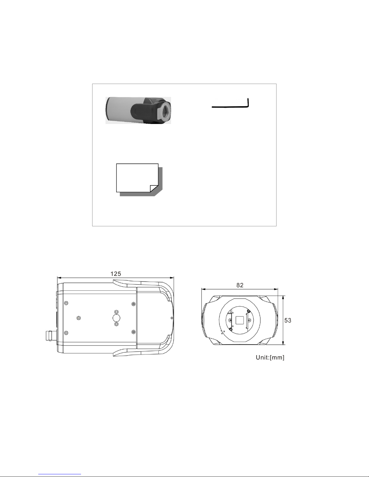
1.2 Package Contents
Please check the package contains the following items listed below.
Camera
Quick Guide
1.3 Dimensions
The IS-IP200-DN dimensions are shown below.
Back focus adjuster
Page 5
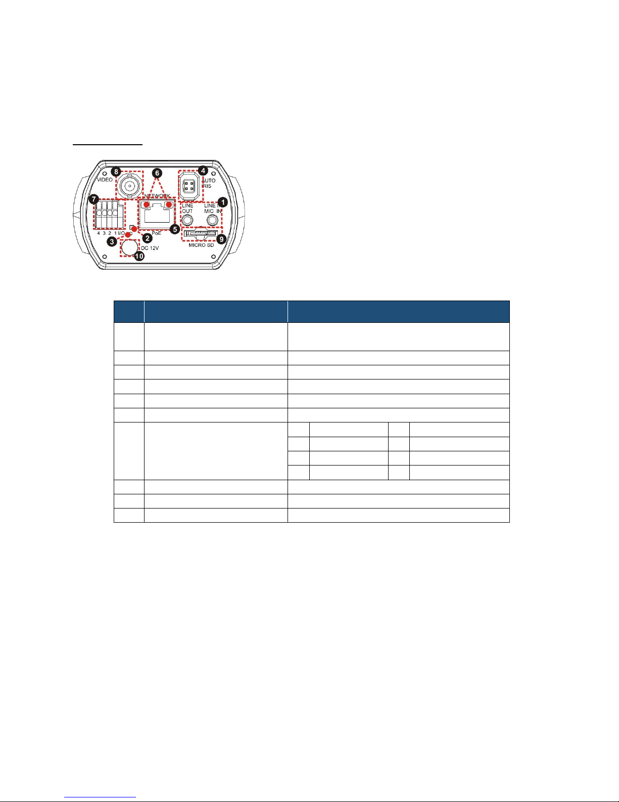
1.4 Connectors
No.
Connector
Definition
1
LINE OUT & LINE IN /
MIC IN
Two-way audio transmission
2
Power LED
Power connection indication (green light)
3
Reset button
Reset to factory default
4
AUTO IRIS connector
Auto iris lens connector
5
NETWORK (with PoE)
RJ-45 connector
6
Network LEDs
Network connection and activity indication
1
Output+
5
GND
2
Output-
6
D- 3 Input+
7
D+ 4 Input-
8
VIDEO (BNC connector)
For video output
9
Micro SD Card slot
For video recording storage
10
DC 12V connector
External power connection
The diagram below shows the IS-IP200-DN reset button and various connectors. Definition for
each will be given as follows.
DC 12V / PoE
7 Alarm I/O
Page 6

2. Camera Cabling
C/CS Mount Adapter
Completion
Please follow the instructions below to complete the IS-IP200-DN installation.
2.1 Connect Power
Please refer to SECTION: CONNECTORS. Alternatively, connect the Ethernet cable to the
camera’s PoE port and plug the other end of the cable into a PoE switch.
NOTE: If us ing PoE, make sure Power Sourcing Equipment (PSE) is in use in the
network.
2.2 Connect Ethernet Cable
Use of Category 5 Ethernet cable is recommended for network connection; to have best
transmission quality, cable length shall not exceed 100 meters. Connect one end of the
Ethernet cable to the RJ-45 connector of the IS-IP200-DN, and the other end of the cable to the
network switch or PC. The RJ-45 port networks without routing to the outside plant.
NOTE: I n some cases, Ethernet crossover cable might be needed when connecting the
IS-IP200-DN directly to the PC.
Check the status of the link indicator and activity indicator LEDs; if the LEDs are unlit, please
check the LAN connection.
Green Link Light indicates good network connection.
Orange Activity Light flashes for network activity indication.
2.3 Lens Mounting
If using C-Mount lens, after removing the camera’s plastic cover, users need to mount the C/CS
mount adapter to the camera. Then attach the lens onto the C/CS mount adapter, as the
illustrations shown below.
Page 7

2.4 Connect Alarm I/O
DC 12V / PoE
PIN 1: Output+
Items
System Requirement
1. Intel® Pentium® M, 2.16 GHz o r
2. 2 GB RAM or more
Operating System
Windows VISTA/ Windows XP/ Windows 7
Web Browser
Microsoft Internet Explorer 6.0 or later
10Base-T (10 Mbps) or 100Base-TX (100 Mbps)
Viewer
ActiveX control plug-in for Microsoft IE
The camera equips one alarm input and one relay output for alarm application. Refer to alarm
pin definition below to connect alarm devices to the IS-IP200-DN if needed.
PIN 2: OutputPIN 3: Input+
PIN 4: Input-
3. System Requirements
To access the IS-IP200-DN via web browser, please ensure your PC has a good network
connection, and meets system requirements as described below.
Personal Computer
Intel® Core
Firefox
Chrome
Safari
TM
2 Duo, 2.0 GHz
Network Card
operation
Page 8

4. Access Camera
Step 1. Power your camera using the correct power source (PoE switch, PoE injector, or
12V adapter).
Step 2. Download, install, and run sentryView™, Sentry360’s camera configuration tool,
here: http://sentry360.com/product/sentryview/
Step 3. Click the Scan button in sentryView™ to scan your network for connected cameras.
Step 4. To automatically configure your camera network settings, check the boxes of the
cameras you want to configure. Then click Auto Configure.
Page 9

Step 5. Confirm your network settings and click Configure.
Step 6. To manually configure your cameras, click Edit Camera Values at the bottom right,
enter your IP Address, Subnet Mask, Gateway, and DHCP settings. Click Apply to
save these values.
Step 7. Your cameras are now configured. If you are using sentryCore™ as your Video
Management System, please download the latest version here:
http://sentry360.com/product/sentrycore/
Step 8. Right click on a camera and select Browse. The prompt for entering the default
username and password will appear for logging in to the IS-IP200-DN.
Page 10

The default login ID and password for the Administrator are:
Login ID
Password
Admin
1234
NOTE: I D and password are case sensitive.
Installing DC Viewer Software Online
For the initial access to the IS-IP200-DN, a client program, DC Viewer, will be automatically
installed to the PC when connecting to the camera.
If the web browser doesn’t allow DC Viewer installation, please check the Internet security
settings or ActiveX controls and plug-ins settings (refer to A
PPENDIX B: SETUP INTERNET
SECURITY) to continue the process.
The Information Bar (just below the URL bar) may come out and ask for permission to install the
ActiveX Control for displaying video in browser. Right click on the Information Bar and select
<Install ActiveX Control…> to allow the installation. Then the security warning window will pop
up. Click on <Install> to carry on software installation.
The download procedure of DC Viewer software is specified as follows.
Step 1. In the DC Viewer installation window, click on <Next> to s tart installation.
Step 2. The status bar will show the installation progress. After the installation is completed,
click on <Finish> to exit the installation process.
Step 3. Click on <Finish> to close the DC Viewer installation page.
Once the DC Viewer is successfully installed, the IS-IP200-DN Home p age will be able to
correctly display as the figure below.
Page 11

Image and Focus Adjustment
The image displays on the Home page when successfully accessing to the IS-IP200-DN. Adjust
zoom and focus as necessary to produce a clear image.
Note: Please refer to IS-IP200-DN
MENU TREE for more button function detail.
Page 12

5. Configure Video Streams
Users can setup Video Resolution on the Video Format page of th e user-friendly browser-based
configuration interface.
Video Format can be found under this path: Streaming > Video Format.
Click on <Save> to confirm the setting.
Page 13

6. Configuration Files Export / Import
To export/ import configuration files, users can access the Maintenance page on the userfriendly browser-based configuration interface.
The Maintenance setting can be found under this path: System > Maintenance.
Users can export configuration files to a specified location and retrieve data by uploading an
existing configuration file to the IS-IP200-DN.
Export
Users can save the system settings by exporting the configuration file (.bin) to a specified
location for future use. Click on the <Export> button, and the popup File Download window will
come out. Click on <Save> and specify a desired location for saving the configuration file.
Upload
To copy an existing configuration file to the IS-IP200-DN, please first click on <Browse> to
select the configuration file, and then click on the <Upload> button for uploading.
Page 14

Appendix A: Delete the Existing DC Viewer
For users who have installed the DC Viewer in the PC previously, please first remove the
existing DC Viewer from the PC before accessing the IS-IP200-DN.
Deleting the DC Viewer
In the Windows <Start Menu>, activate <Control Panel>, and then double click on <Add or
Remove Programs>. In the <Currently installed programs> list, select <DCViewer> and click on
the button <Remove> t o uninstall the existing DC Viewer.
Deleting Temporary Internet Files
To improve browser performance, it is suggested to clean up all the files in the <Temporary
Internet Files>. The procedure is as follows.
Step 1. In the web browser, click on the <Tools> tab on the menu bar and select <Internet
Options>.
Step 2. Click on the <Delete> button under the <Browsing History> section.
Step 3. In the opened window, tick the box beside <Temporary Internet Files> and click on
<Delete> to start deleting the files.
Page 15

Appendix B: Setup Internet Security
ActiveX controls and plug-ins settings:
player.
If ActiveX control installation is blocked, please either set Internet security level to default or
change ActiveX controls and plug-ins settings.
Internet Security Level: Default
Step 1. Start the Internet Explorer (IE).
Step 2. Click on the <Tools> tab on the menu bar and select <Internet Options>.
Step 3. Click on the <Security> tab, and select <Internet> zone.
Step 4. Down the page, click on the <Default Level> button and click on <OK> to confirm
the setting. Close the browser window, and restar t a new one later to access the ISIP200-DN.
ActiveX Controls and Plug-ins Settings
Step 1. Repeat Steps 1 ~ 3 of the previous section above.
Step 2. Down the page, click on the <Custom Level> button to change ActiveX controls and
plug-ins settings. The Security Settings window will pop up.
Step 3. Under <ActiveX controls and plug-ins>, set ALL items (as listed below) to <Enable>
or <Prompt>. Please note that the items vary by IE version.
1. Binary and script behaviors.
2. Download signed ActiveX controls.
3. Download unsigned ActiveX controls.
4. Allow previously unused ActiveX controls to run without prompt.
5. Allow Scriptlets.
6. Automatic prompting for ActiveX controls.
7. Initialize and script ActiveX controls not marked as safe for scripting.
8. Run ActiveX controls and plug-ins.
9. Only allow approved domains to use ActiveX without prompt.
10. Script ActiveX controls marked safe for scripting*.
11. Display video and animation on a webpage that does not use external media
Step 4. Click on <OK> to accept the settings. A prompt window will appear for confirming
the setting changes, click <Yes(Y)> to close the Security Setting window.
Step 5. Click on <OK> to close the Internet Options screen.
Step 6. Close the browser window, and restart a new one to access the IS-IP200-DN.
Page 16

Appendix C: Back Focus Adjustment
When to adjust back focus
Back Focus refers to the distance from the rear lens element to the camera focal plane. In most
cases, it is required to adjust back focus only when the camera’s lens cannot hold focus
throughout its zoom range.
Requirements
Tools required when carrying out back focus adjustment include:
1. Back focus adjuster (in the camera’s package)
2. Test chart / contrasting object
How to adjust back focus
Step 1. Set the camera on a stable mount, with the test chart or object at least 75 feet (23
meters) away (or as far as possible).
Step 2. Make sure the iris is wide open. Therefore, it is advised to keep the environment in
low light condition.
Step 3. Adjust the focus to infinite far (∞).
Step 4. Turn the zoom to the extreme telephoto position, and then focus on the subject.
Step 5. Set the zoom to wide-angle position.
Step 6. Loosen the back focus ring’s retaining screw with the supplied adjuster, and adjust
the back focus ring for sharp picture.
Step 7. Repeat steps 3 ~ 6 until focus can stay the same throughout the zoom range.
Step 8. Tighten the back focus ring’s retaining screw to fix the ring.
 Loading...