

Page 1

IS-DM200
User's Manual
Ver 1.0
©Sentry360 2015
Page 2

Table of Contents
1. Overview ............................................................................................................................ 3
1.1 Features ...................................................................................................................... 3
1.2 Package Contents........................................................................................................ 4
1.3 Dimensions .................................................................................................................. 5
1.4 Connectors .................................................................................................................. 6
2. Camera Cabling ................................................................................................................. 8
2.1 Power Connection........................................................................................................ 8
2.2 Ethernet Cable Connection .......................................................................................... 8
2.3 Alarm I/O Connection ................................................................................................... 8
3. System Requirements ...................................................................................................... 9
4. Access Camera ................................................................................................................10
5. Configure Video Streams ................................................................................................15
6. Configuration Files Export / Import ................................................................................16
Appendix A: Delete the Existing DC Viewer ..........................................................................17
Appendix B: Setup Internet Security .....................................................................................18
Page 3

1. Overview
The IS-DM200 camera is a Quad-streaming, H.264 & MJPEG encoding, 2.0 Megapixel
resolution, IP-addressable, network camera. It is designed to deliver full-motion, high-definition,
progressive scan digital video across local area networks. The IS-DM200 features a 1/2.8”
CMOS sensor, Power over Ethernet, 21 IR LED, Audio-In and Audio-Out. The IS-DM200 is a
cost-effective, high-level, megapixel network camera.
1.1 Features
Sony Progressive Scan CMOS Sensor
2M Resolution
Quad Streams Support
Dual Streams- Full HD 1080P Real-time + Full HD 1080P Real-time
Quad Stream Compression-
H.264 Baseline / Main / High Profile + MJPEG
Multi-language Support
Tampering Alarm
Ultra Dynamic Range
Motion Detection
Privacy Masks
3D / 2D Noise Reduction
Network Failure Detection
Day/Night (ICR)
IR LED Module (working distance up to 25 m)
Digital Image Stabilizer (DIS)
microSD Support
ONVIF Support
Page 4
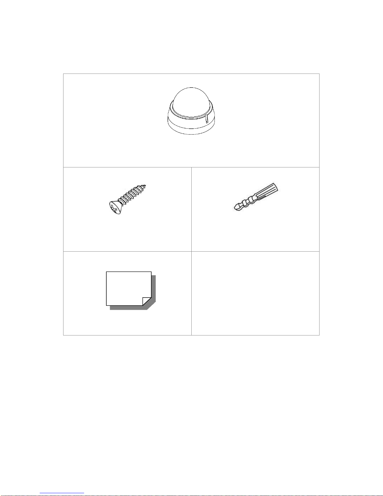
1.2 Package Contents
Camera
Self-Tapping Screw (x3)
Plastic Screw Anchor (x3)
Quick Guide
Please check the package contains the following items listed below.
Page 5
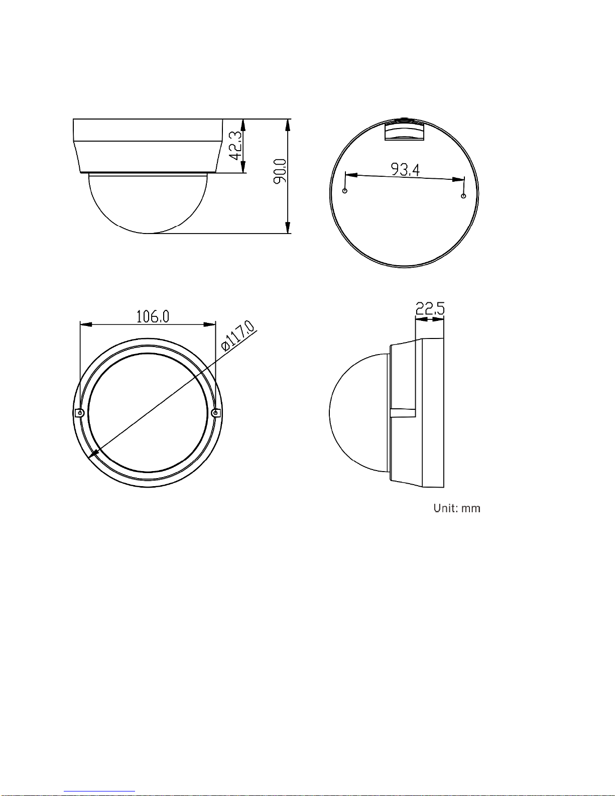
1.3 Dimensions
The dimensions of the camera are shown below.
Page 6
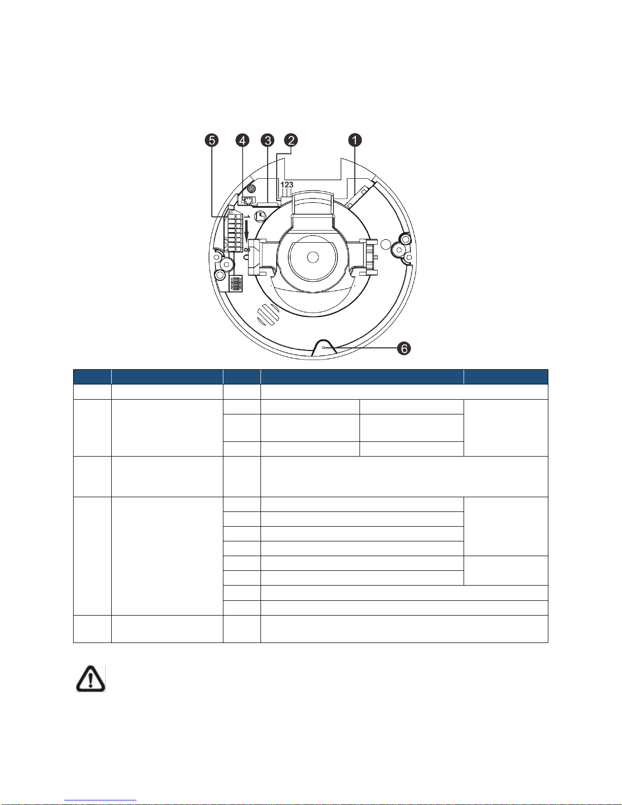
1.4 Connectors
No.
Connector
Pin
Definition
Remarks
1
RJ-45
-
For network and PoE connection
2
Power
(DC 12V / AC 24V)
1
DC 12V
AC 24V 1
Power
connection
2
DC 12V
Reserved
AC 24V GND
3
DC 12V GND
AC 24V 2
3
microSD Card Slot
-
Insert the microSD card into the card slot to store
videos and snapshots. Do not remove the microSD
card when the camera is powered on.
5
Alarm & Audio I/O
1
Alarm In –
Alarm
connection
2
Alarm In +
3
Alarm Out –
4
Alarm Out +
5
Audio Out R
Audio Out
6
Audio Out L
7
GND
8
Audio In
6
Default Button
-
Press the button with a proper tool for at least 20
seconds to restore the system.
The diagram below shows the camera's default button and various connectors. Definition for
each connector is given as follows.
NOTE: It is not recommended to record with the microSD card for continuously, as it
may not be able to support long term continuous data read/write. Please contact the
manufacturer of the microSD card for information regarding reliability and life
expectancy.
Page 7

Page 8

2. Camera Cabling
Green Link Light indicates good network connection.
Orange Activity Light flashes for network activity indication.
Before users connect cables, make sure that all cables and the power adaptor are placed in dry
and well-waterproofed environments, e.g. waterproof boxes. The purpose is to prevent moisture
accumulation inside the camera and moisture penetration into cables, which might lead to
camera breakdown. Please refer to the following sections for camera connection.
2.1 Power Connection
For power connection, please refer to section CONNECTORS. Alternatively, users can power the
camera by PoE if a Power Sourcing Equipment (PSE) switch is available. Please refer to the
section below for Ethernet cable connection.
2.2 Ethernet Cable Connection
For best transmission quality, cable length shall not exceed 100 meters. Connect one end of the
Ethernet cable to the RJ-45 connector of the camera / function cable, and plug the other end of
the cable to the network switch or PC.
NOTE: In some cases, Ethernet crossover cable might be needed when connecting the
IP camera directly to the PC.
Check the status of the link indicator and the activity indicator LEDs. If the LEDs are unlit,
please check the LAN connection.
2.3 Alarm I/O Connection
Connect alarm devices to the first 4 pins of the camera’s 8-pin terminal block. Refer to section
CONNECTORS for the pin definitions.
Page 9

3. System Requirements
Items
System Requirement
Personal Computer
Intel® Pentium® M, 2.16 GHz or
Intel® CoreTM2 Duo, 2.0 GHz
2 GB RAM or more
Operating System
Windows VISTA / Windows XP / Windows 7
Web Browser
Microsoft Internet Explorer 6.0 or later
Firefox
Chrome
Safari
Network Card
10Base-T (10 Mbps),100Base-TX (100 Mbps) or
1000Base-T (1000 Mbps) operation
Viewer
ActiveX control plug-in for Microsoft IE
To access the camera via web browser, please ensure the PC has a good network connection,
and meets system requirements as described below.
Page 10

4. Access Camera
Step 1. Power your camera using the correct power source (PoE switch, PoE injector, or
12V adapter).
Step 2. Download, install, and run sentryView™, Sentry360’s camera configuration tool,
here: http://sentry360.com/product/sentryview/
Step 3. Click the Scan button in sentryView™ to scan your network for connected
cameras.
Step 4. To automatically configure your camera network settings, check the boxes of the
cameras you want to configure. Then click Auto Configure.
Page 11
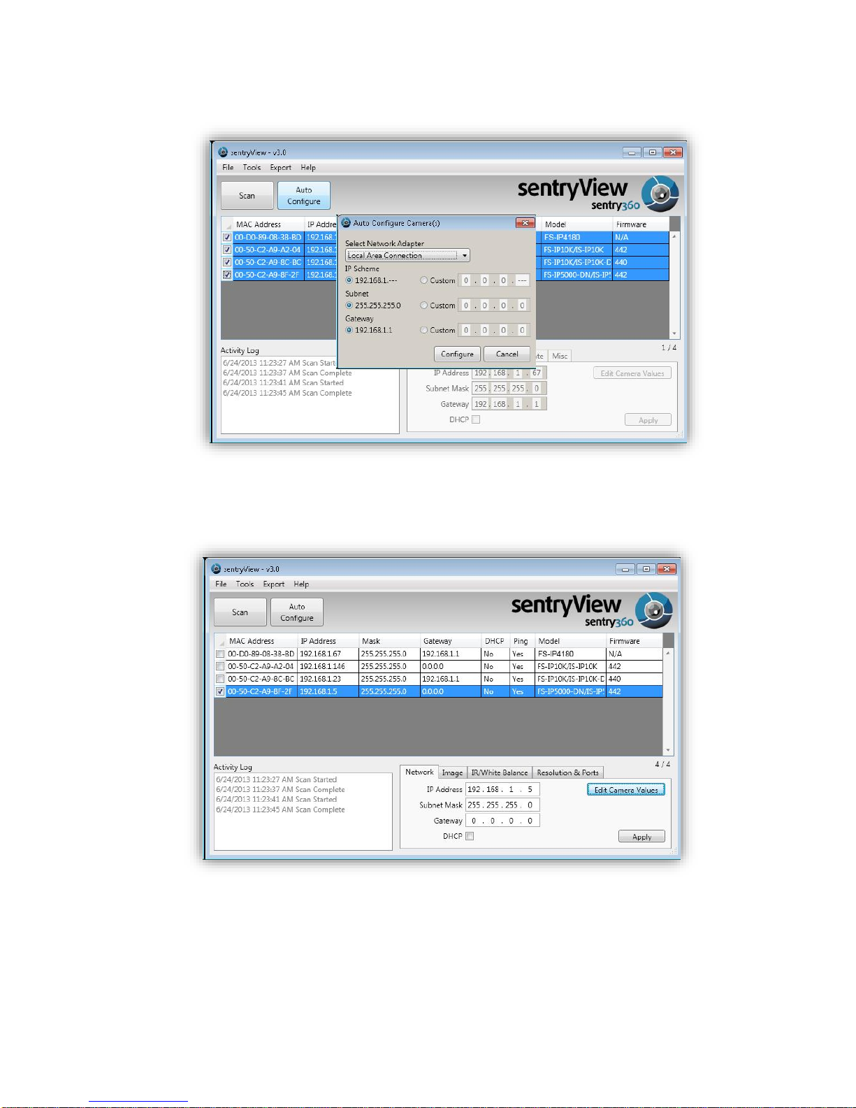
Step 5. Confirm your network settings and click Configure.
Step 6. To manually configure your cameras, click Edit Camera Values at the bottom
right, enter your IP Address, Subnet Mask, Gateway, and DHCP settings. Click
Apply to save these values.
Step 7. Your cameras are now configured. If you are using sentryCore™ as your Video
Management System, please download the latest version here:
http://sentry360.com/product/sentrycore/
Right click on a camera and select Browse. The prompt for entering the default username and
password will appear for logging in to the camera.
Page 12

The default login ID and password for the Administrator are:
Login ID
Password
Admin
1234
NOTE: ID and password are case sensitive.
Installing DC Viewer Software Online
For initial access to the IP camera, a client program, DC Viewer, will be automatically installed
to the PC when connecting to the camera.
If the web browser doesn’t allow DC Viewer installation, please check the Internet security
settings or ActiveX controls and plug-ins settings (refer to APPENDIX B: SETUP INTERNET
SECURITY) to continue the process.
The Information Bar (just below the URL bar) may come out and ask for permission to install the
ActiveX Control for displaying video in browser. Right click on the Information Bar and select
<Install ActiveX Control…> to allow the installation.
The download procedure of DC Viewer software is specified as follows.
Step 1. In the DC Viewer installation window, click on <Next> to start the installation.
Step 2. The status bar will show the installation progress. After the installation is
completed, click on <Finish> to exit the installation process.
Step 3. Click on <Finish> to close the DC Viewer installation page.
Once the DC Viewer is successfully installed, the home page of the camera will be shown as
the figure below.
Page 13

Page 14

Zoom and Focus Adjustment
Zoom and focus can be adjusted using the adjustment bars on the camera lens inside the dome
cover. To adjust zoom and focus, please detach the dome cover first. Use a Phillips screwdriver
to loosen the two screws attaching the cover. Detach the dome cover. Then use the zoom
adjustment bar and the focus adjustment bar (positions shown in the following figure) to adjust
zoom and focus.
Page 15
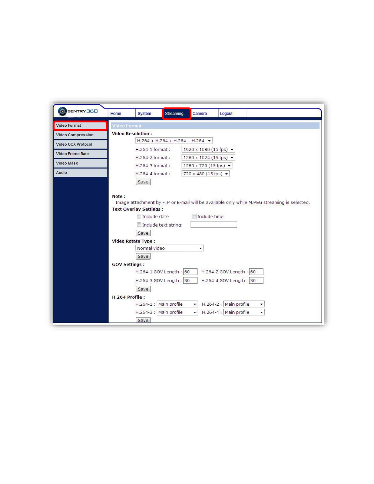
5. Configure Video Streams
Users can setup Video Resolution on the Video Format page of the user-friendly browser-based
configuration interface.
Video Format can be found under this path: Streaming > Video Format.
Click on <Save> to confirm the setting.
Page 16

6. Configuration Files Export / Import
To export / import configuration files, users can access the Maintenance page of the
configuration interface.
The Maintenance settings can be found under this path: System > Maintenance.
Users can export configuration files to a specified location and retrieve data by uploading an
existing configuration file to the camera.
Export
Users can save the system settings by exporting the configuration file (.bin) to a specified
location for future use. Click on the <Export> button, and the popup File Download window will
appear. Click on <Save> and specify a desired location for saving the configuration file.
Upload
To copy an existing configuration file to the camera, click on <Browse> to select the
configuration file, and then click on the <Upload> button to import it.
Page 17

Appendix A: Delete the Existing DC Viewer
For users who have previously installed the DC Viewer, please first remove the existing DC
Viewer before accessing the camera.
Deleting the DC Viewer
In the Windows <Start Menu>, select <Control Panel>, and then double click on <Add or
Remove Programs>. In the <Currently installed programs> list, select <DCViewer> and click on
the button <Remove> to uninstall the existing DC Viewer.
Deleting Temporary Internet Files
To improve browser performance, it is suggested to clean up all the files in the <Temporary
Internet Files>. The procedure is as follows.
Step 1. In the web browser, click on the <Tools> tab on the menu bar and select <Internet
Options>.
Step 2. Click on the <Delete> button under the <Browsing History> section.
Step 3. In the opened window, tick the box beside <Temporary Internet Files> and click on
<Delete> to start deleting the files.
Page 18

Appendix B: Setup Internet Security
ActiveX controls and plug-ins settings:
1. Binary and script behaviors.
2. Download signed ActiveX controls.
3. Download unsigned ActiveX controls.
4. Allow previously unused ActiveX controls to run without prompt.
5. Allow Scriptlets.
6. Automatic prompting for ActiveX controls.
7. Initialize and script ActiveX controls not marked as safe for scripting.
8. Run ActiveX controls and plug-ins.
9. Only allow approved domains to use ActiveX without prompt.
10. Script ActiveX controls marked safe for scripting*.
11. Display video and animation on a webpage that does not use external media
player.
If ActiveX control installation is blocked, please either set Internet security level to default or
change ActiveX controls and plug-ins settings.
Internet Security Level: Default
Step 1. Start the Internet Explorer (IE).
Step 2. Click on the <Tools> tab on the menu bar and select <Internet Options>.
Step 3. Click on the <Security> tab, and select <Internet> zone.
Step 4. Down the page, click on the <Default Level> button and click on <OK> to confirm
the setting. Close the browser window and open a new one to access the camera.
ActiveX Controls and Plug-ins Settings
Step 1. Repeat Steps 1 ~ 3 of the previous section above.
Step 2. Down the page, click on the <Custom Level> button to change ActiveX controls
and plug-ins settings. The Security Settings window will pop up.
Step 3. Under <ActiveX controls and plug-ins>, set ALL items (as listed below) to
<Enable> or <Prompt>. Please note that the items vary by IE version.
Step 4. Click on <OK> to accept the settings. A prompt window will appear for confirming
the setting changes, click <Yes(Y)> to close the Security Setting window.
Step 5. Click on <OK> to close the Internet Options screen.
Close the browser window and open a new one to access the camera.
 Loading...