

Page 1
FullSight™ IP 12.0 Megapixel Ultra-Compact 360° Dome
User Manual
FS-IP12360-V
FS-IP12360-V
Mini Dome IP Camera
User’s Manual
Ver. 1.0
Page 2

1
Table of Contents
1. Overview ................................................................................................................................ 2
1.1 Features ...................................................................................................................... 2
1.2 Package Contents ....................................................................................................... 3
1.5 Function Cables ........................................................................................................... 4
2. Camera Cabling ..................................................................................................................... 5
2.1 Ethernet Cable Connection .......................................................................................... 5
2.3 Alarm I/O Connection .................................................................................................. 5
3. System Requirements .......................................................................................................... 6
4. Access Camera ..................................................................................................................... 7
6. Configuration Files Export / Import ................................................................................... 10
Appendix A: Delete the Existing DC Viewer .............................................................................. 11
Appendix B: Setup Internet Security ......................................................................................... 12
Page 3

2
1. Overview
The FS-IP12360-V camera is an MJPEG or H.264 encoding, 12.0 Megapixel
resolution, IP addressable 360 degree camera. It is designed to deliver
full-motion, high-definition, progressive scan digital video across local area
networks. The FS-IP12360-V features a design with no moving parts, creating a
full 360 degree view. An optically corrected panoramic lens, designed
exclusively for the FullSight™ camera, allows for immersive 360 degree live
view as well as pan-tilt-zoom during playback with the use of Sentry360’s API or
SDK with any 3rd party network video recording software certified partner.
1.1 Features
12.0 Megapixel CMOS Sensor
Maximum Resolution: 4000 x 3000
Maximum Framerate: 20 fps
IR Cut Filter
Full Onvif Compatibility
Motion Detection
PoE 802.3af
100/10 LAN Connection
Protocols: UDP, TCP, HTTP, TFTP, RTSP
Automatic Exposure
Automatic White Balance
Brightness, Contrast, Saturation Controls
1.55mm f-theta Fisheye Lens
microSD Support
ONVIF Support
Page 4
3
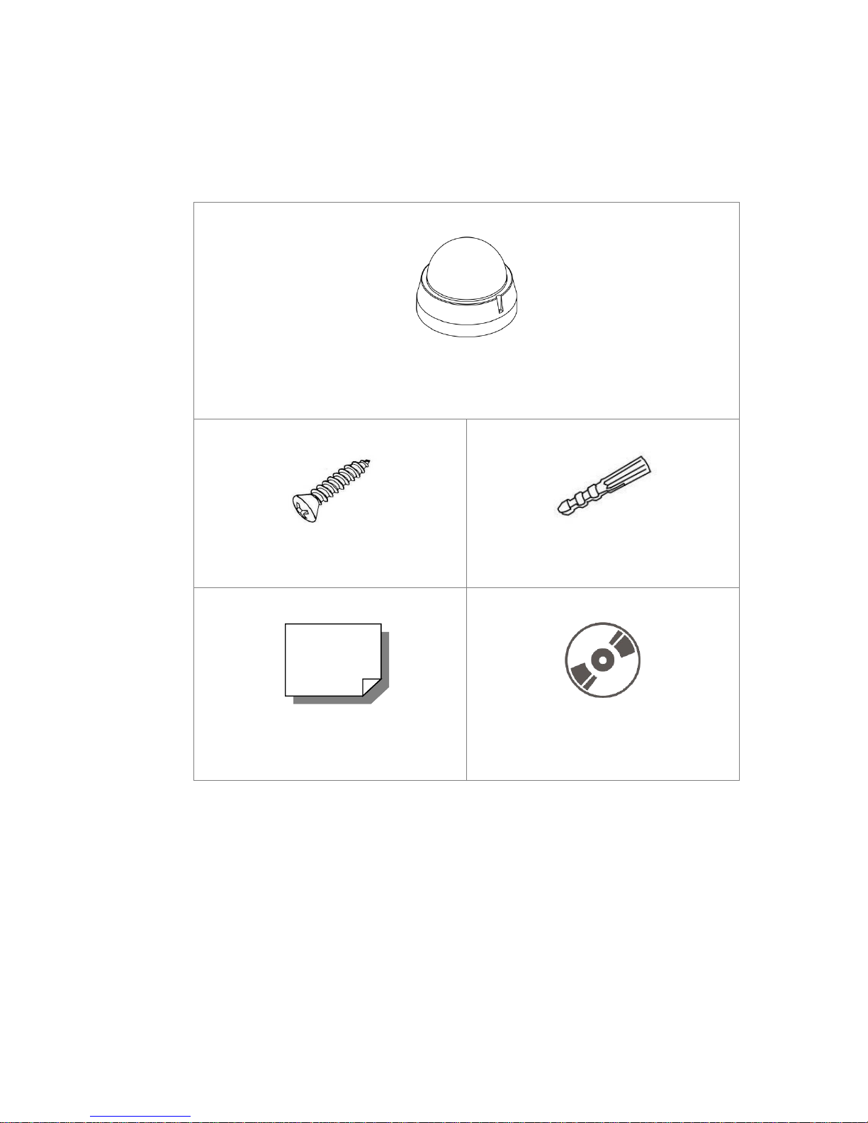
1.2 Package Contents
Please check the package contains the following items listed below.
FS-IP12360-V
Self-Tapping Screw (x3)
Plastic Screw Anchor (x3)
Quick Guide
CD
(bundled software and documentation)
Page 5

4
1.3 Dimensions
The dimensions of the camera are shown below.
1.5 Function Cables
No.
Connector
Pin
Definition
Remarks
1
RJ-45
-
For network and PoE connection
2
Power
(DC 12V / AC 24V)
1
DC 12V –
AC 24V 1
Power
connection
2
GND
3
DC 12V +
AC 24V 2
3
Alarm I/O
1
Alarm In –
Blue
2
Alarm In +
Green
3
Alarm Out –
Yellow
4
Alarm Out +
Orange
4
Audio I/O
Green
Audio Out
Two-way audio
transmission
Pink
Audio In
-
Default Button
-
Dome removal required. Brown button visible
-
microSD Card Slot
-
Dome removal required.
NOTE: It is not recommended to record with the microSD card for 24/7
continuously, as it may not be able to support long term continuous data
read/write. Please contact the manufacturer of the microSD card for
information regarding reliability and life expectancy.
Page 6

5
2. Camera Cabling
Before users connect cables, make sure that all cables and the power adaptor
are placed in dry and well-waterproofed environments, e.g. waterproof boxes.
The purpose is to prevent moisture accumulation inside the camera and
moisture penetration into cables, which might lead to camera breakdown.
2.1 Ethernet Cable Connection
For best transmission quality, cable length shall not exceed 100 meters.
Connect one end of the Ethernet cable to the RJ-45 connector of the camera /
function cable, and plug the other end of the cable to the network switch or PC.
NOTE: In some cases, Ethernet crossover cable might be needed when
connecting the IP camera directly to the PC.
Check the status of the link indicator and the activity indicator LEDs. If the LEDs
are unlit, please check the LAN connection.
Green Link Light indicates good network connection.
Orange Activity Light flashes for network activity indication.
2.3 Alarm I/O Connection
For indoor models, connect alarm devices to the first 4 pins of the camera’s
8-pin terminal block. For outdoor models, connect alarm devices to the 4-pin
terminal block of the All-in-One cable.
Page 7

6
3. System Requirements
To perform the IP camera via web browser, please ensure the PC is in good
network connection, and meet system requirements as described below.
Items
System Requirement
Personal Computer
1. Intel® Pentium® M, 2.16 GHz or
Intel® CoreTM2 Duo, 2.0 GHz
2. 2 GB RAM or more
Operating System
Windows VISTA / Windows XP / Windows 7
Web Browser
Microsoft Internet Explorer 6.0 or later
Firefox
Chrome
Safari
Network Card
10Base-T (10 Mbps),100Base-TX (100 Mbps) or
1000Base-T (1000 Mbps) operation
Viewer
ActiveX control plug-in for Microsoft IE
Page 8

7
4. Access Camera
Step 1. Power your camera using the correct power source (PoE switch, PoE injector, or
12V adapter).
Step 2. Download, install, and run sentryView™, Sentry360’s camera configuration tool,
here: http://sentry360.com/product/sentryview/
Step 3. Click the Scan button in sentryView™ to scan your network for cameras.
Step 4. To automatically configure your camera network settings, check the boxes of the
cameras you want to configure. Then click Auto Configure.
Page 9

8
Step 5. Confirm your network settings and click Configure.
Step 6. To manually configure your cameras, click Edit Camera Values at the bottom
right, enter your IP Address, Subnet Mask, Gateway, and DHCP settings. Click
Apply to save these values.
Step 7. Your cameras are now configured. If you are using sentryCore™ as your Video
Management System, please download the latest version here:
http://sentry360.com/product/sentrycore/
Step 8. Right click on a camera and select Browse. The prompt for entering the default
username and password will appear for logging in to the FS-IP12360-V
The default login ID and password for the Administrator are:
Page 10

9
Login ID
Password
Admin
1234
NOTE: ID and password are case sensitive.
Installing DC Viewer Software Online
For the initial access to the FS-IP12360-V, a client program, DC Viewer, will be automatically
installed to the PC when connecting to the camera.
If the web browser doesn’t allow DC Viewer installation, please check the Internet security settings
or ActiveX controls and plug-ins settings (refer to APPENDIX B: SETUP INTERNET SECURITY) to
continue the process.
The Information Bar (just below the URL bar) may come out and ask for permission to install the
ActiveX Control for displaying video in browser. Right click on the Information Bar and select <Install
ActiveX Control…> to allow the installation. Then the security warning window will pop up. Click on
<Install> to carry on software installation.
The download procedure of DC Viewer software is specified as follows.
Step 1. In the DC Viewer installation window, click on <Next> to start installation.
Step 2. The status bar will show the installation progress. After the installation is completed,
click on <Finish> to exit the installation process.
Step 3. Click on <Finish> to close the DC Viewer installation page.
Once the DC Viewer is successfully installed, the FS-IP12360-V Home page will be able to correctly
display as the figure below.
Page 11

10
6. Configuration Files Export / Import
To export / import configuration files, users can access the Maintenance page
on the user-friendly browser-based configuration interface.
The Maintenance setting can be found under this path: System> Maintenance.
Users can export configuration files to a specified location and retrieve data by
uploading an existing configuration file to the camera. This is especially
convenient to make multiple cameras having the same configuration.
Export
Users can save the system settings by exporting the configuration file (.bin) to a
specified location for future use. Click on the <Export> button, and the popup
File Download window will come out. Click on <Save> and specify a desired
location for saving the configuration file.
Upload
To upload a configuration file to the camera, click on <Browse> to select the
configuration file, and then click on the <Upload> button for uploading.
Page 12

11
Appendix A: Delete the Existing DC Viewer
For users who have installed the DC Viewer in the PC previously, please remove the
existing DC Viewer from the PC before accessing to the IP camera.
Deleting the DC Viewer
In the Windows <Start Menu>, activate <Control Panel>, and then double click on
<Add or Remove Programs>. In the <Currently installed programs> list, select <DCViewer>
and click on the button <Remove> to uninstall the existing DC Viewer.
Deleting Temporary Internet Files
To improve browser performance, it is suggested to clean up all the files in the <Temporary
Internet Files>. The procedure is as follows.
Step 1: In the web browser, click on the <Tools> tab on the menu bar and select <Internet
Options>.
Step 2: Click on the <Delete> button under <Browsing history> section. Then tick the
box beside the <Temporary Internet Files>.
Step 3: Click on <Delete> to start deleting the files.
Page 13

12
Appendix B: Setup Internet Security
If ActiveX control installation is blocked, please either set Internet security level to default or
change ActiveX controls and plug-ins settings.
Internet Security Level: Default
Step 1: Start the Internet Explorer (IE).
Step 2: Click on the <Tools> tab on the menu bar and select <Internet Options>.
Step 3: Click on the <Security> tab, and select <Internet> zone.
Step 4: Down the page, click on the <Default Level> button and click on <OK> to confirm
the setting. Close the browser window, and restart a new one later to access the IP
camera.
ActiveX Controls and Plug-ins Settings
Step 1: Repeat Step 1 to Step 3 of the previous section above.
Step 2: Down the page, click on the <Custom Level> button to change ActiveX controls
and plug-ins settings. The Security Settings window will pop up.
Step 3: Under <ActiveX controls and plug-ins>, set ALL items (as listed below) to
<Enable> or <Prompt>. Please note that the items vary by IE version.
ActiveX controls and plug-ins settings:
1. Binary and script behaviors.
2. Download signed ActiveX controls.
3. Download unsigned ActiveX controls.
4. Allow previously unused ActiveX controls to run without prompt.
5. Allow Scriptlets.
6. Automatic prompting for ActiveX controls.
7. Initialize and script ActiveX controls not marked as safe for scripting.
8. Run ActiveX controls and plug-ins.
9. Only allow approved domains to use ActiveX without prompt.
10. Script ActiveX controls marked safe for scripting*.
11. Display video and animation on a webpage that does not use external media player.
Step 4: Click on <OK> to accept the settings. A prompt window will appear for confirming
the setting changes, click <Yes(Y)> to close the Security Setting window.
Step 5: Click on <OK> to close the Internet Options screen.
Step 6: Close the browser window, and restart a new one later to access the IP camera.
 Loading...