

Page 1
FS-DM-DOME-HB
FullSight™ Dome with Heater Blower
Installation Guide
Revision: 10/9/2014
Copyright © 2007-2013 Sentry360
1
Page 2
Model
FS-DM-DOME
Options
Blower / Heater/ POE Board
Input Voltage
DC48V POE
Power Consumption
9.6W oHs
Operational Range
Temperature / -40~+60°C
Humidity / 0~95%
Heater Blower
Heater : ON 4
±3
Size
IP DOME
φ148.4(W)x160.8(H) m/m
φ130.5(W)x155.3(H) m/m
Weight
1.8 KG
Material
Body:Aluminum(ADC-12)
Window: Transparent cover
Water Proof Rating
IP66
Accessories Supplied
5mm Wrench (1ea), Plastic Expansion/Plug (4ea), M4 steel screw – (4ea), 1
Network Cable
I. Description
The FS-DM-DOME-HB is suitable for indoor and outdoor use, and has
been designed for rapid installation. The extended dome cover permits
unhindered 360° viewing. The case has been produced using diecastings aluminum materials, powder coating and a high impactresistant, ultra-transparent cover. Both side and rear entry cable ports
are provided. The housing is IP66 rated.
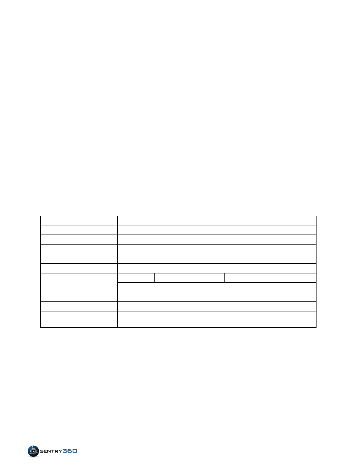
II. Specifications
FS-DM-DOME-HB 2
Installation Guide
Page 3
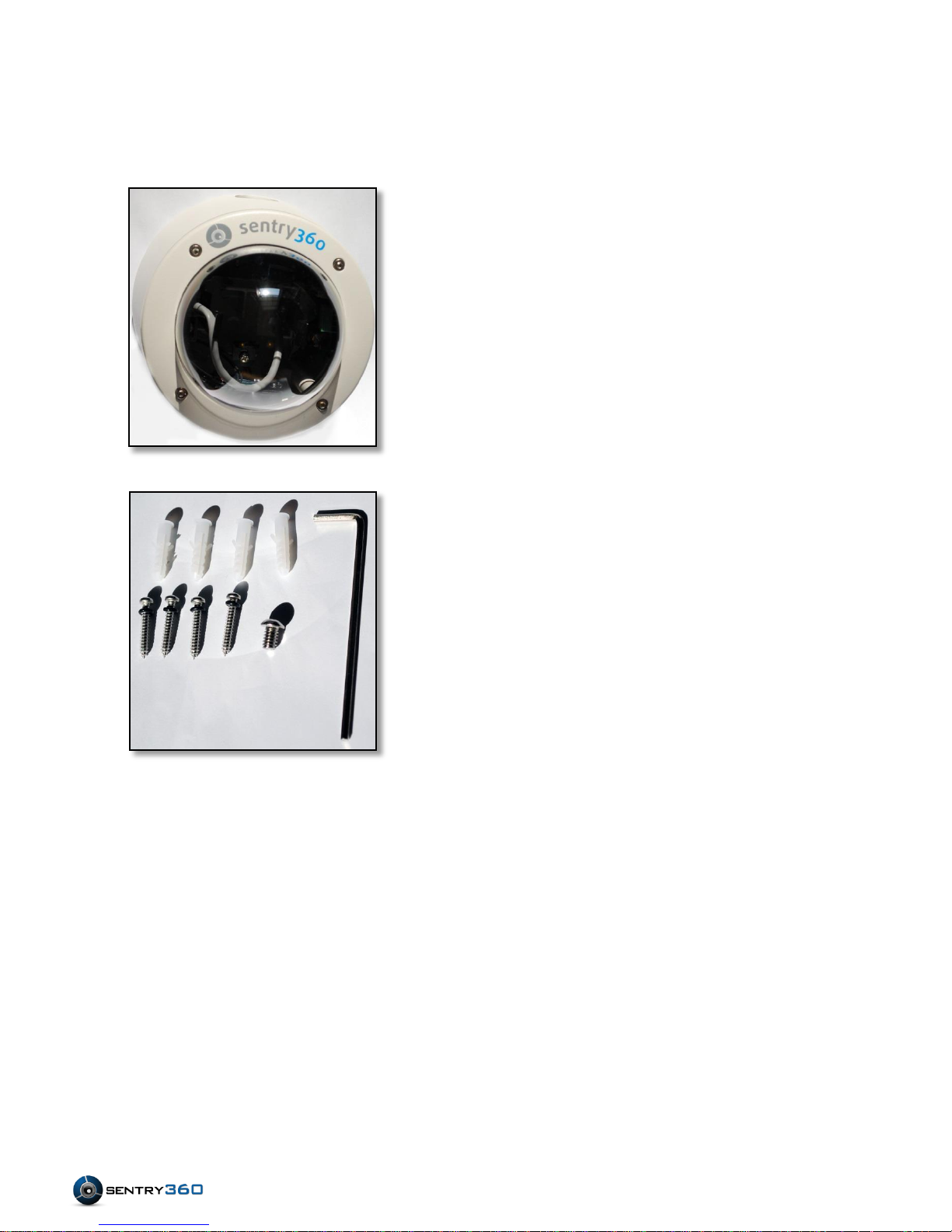
III. Package Contents
Dome Enclosure (1)
Hexagonal Allen Wrench (1)
Plastic Screw Anchors (4)
1” Philips Screws (4)
3/8
th
” Hexagonal Screw (1)
Ethernet Cable (1)
FS-DM-DOME-HB 3
Installation Guide
Page 4
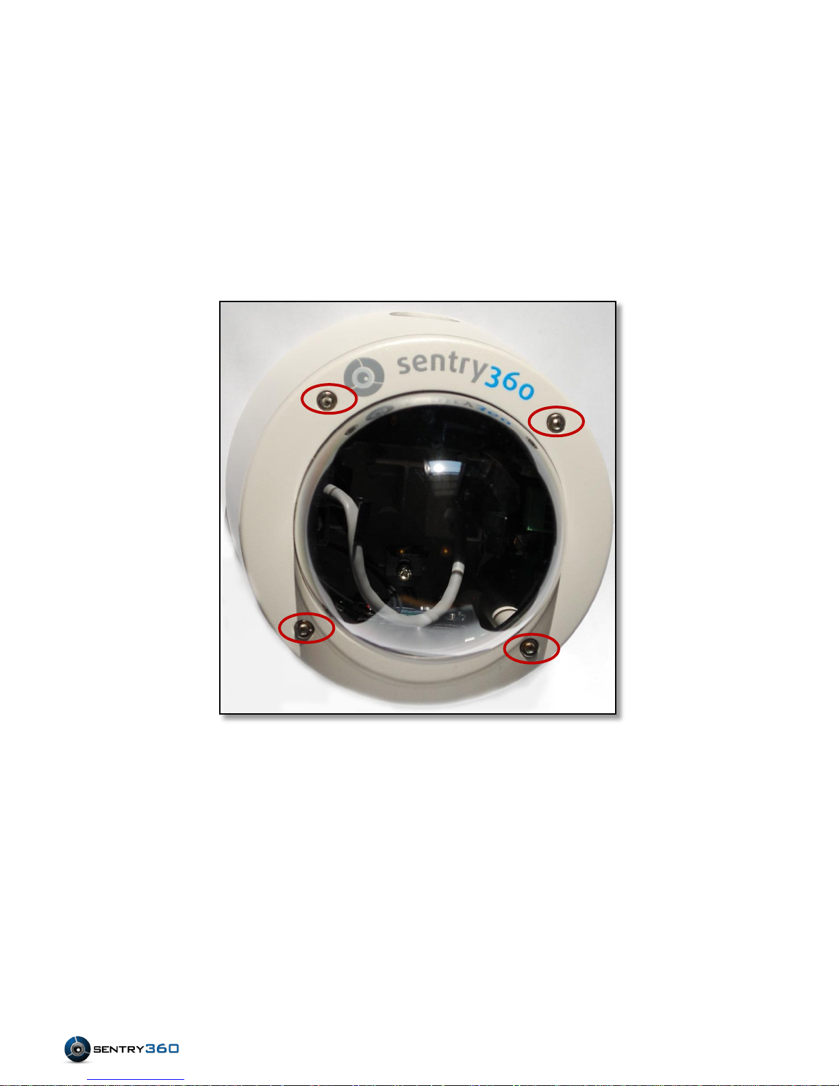
IV. FullSight™ Camera Installation Instructions:
A. Locate and loosen Screws.
a) Find the 4 Hexagonal screws located around the ring of the
glass enclosure.
FS-DM-DOME-HB 4
Installation Guide
Page 5

b) Loosen the 4 screws with the hexagonal wrench packaged
with the dome.
FS-DM-DOME-HB 5
Installation Guide
Page 6

B. Remove the vandal-proof lid by lifting it from the base.
Blower
Camera Plate
POE Port
Optional DC
Conduit Holes
Internal components overview:
FS-DM-DOME-HB 6
Installation Guide
Page 7

C. Locate and remove the camera plate by unscrewing the Philips
screw attaching it to the dome.
D. Attach the camera plate to the camera using the 3/8
packaged with the dome.
th
” screw
FS-DM-DOME-HB 7
(NOTE: Washers may be required)
Installation Guide
Page 8

Side Conduit Knockout Hole
Bottom Conduit Knockout
Hole
E. Select a conduit knockout hole
Depending on what surface you are mounting the camera to,
choose between one of the two conduit knockout holes to use
for the cables:
Conduit knockout holes:
FS-DM-DOME-HB 8
Installation Guide
Page 9

F. Remove the plug of the conduit knockout hole you have
selected by using a large flathead screwdriver.
G. Insert your external Ethernet cable through the conduit
knockout hole and plug it into the open POE port.
FS-DM-DOME-HB 9
Installation Guide
Page 10

H. Connect the Ethernet cable provided with the dome to the
camera.
(NOTE: If powering camera with DC power, you can connect your external network cable
directly to the camera for direct data transmission)
FS-DM-DOME-HB 10
Installation Guide
Page 11

I. Slide the camera into place and lock it into position. (The
brackets will clip around the camera)
J. Screw the camera bracket back onto the dome to fasten the
camera in place.
FS-DM-DOME-HB 11
Installation Guide
Page 12

K. Plug in your 12V DC cable into the green 12V DC connector.
(Optional)
Flip the switch next to the 12V DC connector to the right.
(NOTE: Only perform this step if you are using 12V DC power. If using POE make sure the switch is
FS-DM-DOME-HB 12
flipped to the left)
Installation Guide
Page 13

L. Place the vandal-proof lid back on the dome and tighten the
four hexagonal screws. Make sure that the screws are
tightened snug, but not overly tightened. Screwing these in
too tight can damage the rubber gaskets.
(Note: It is the installer’s responsibility to ensure that the conduit knockout hole is sealed properly.)
FS-DM-DOME-HB 13
Installation Guide
Page 14

M. Located on the bottom of the dome are 4 punch-out holes.
Screws can be used to either surface mount the dome or to
attach it to an adapter.
FS-DM-DOME-HB 14
Installation Guide
 Loading...