

Page 1
Original Instructions
Installation, Operation
&Maintenance Manual
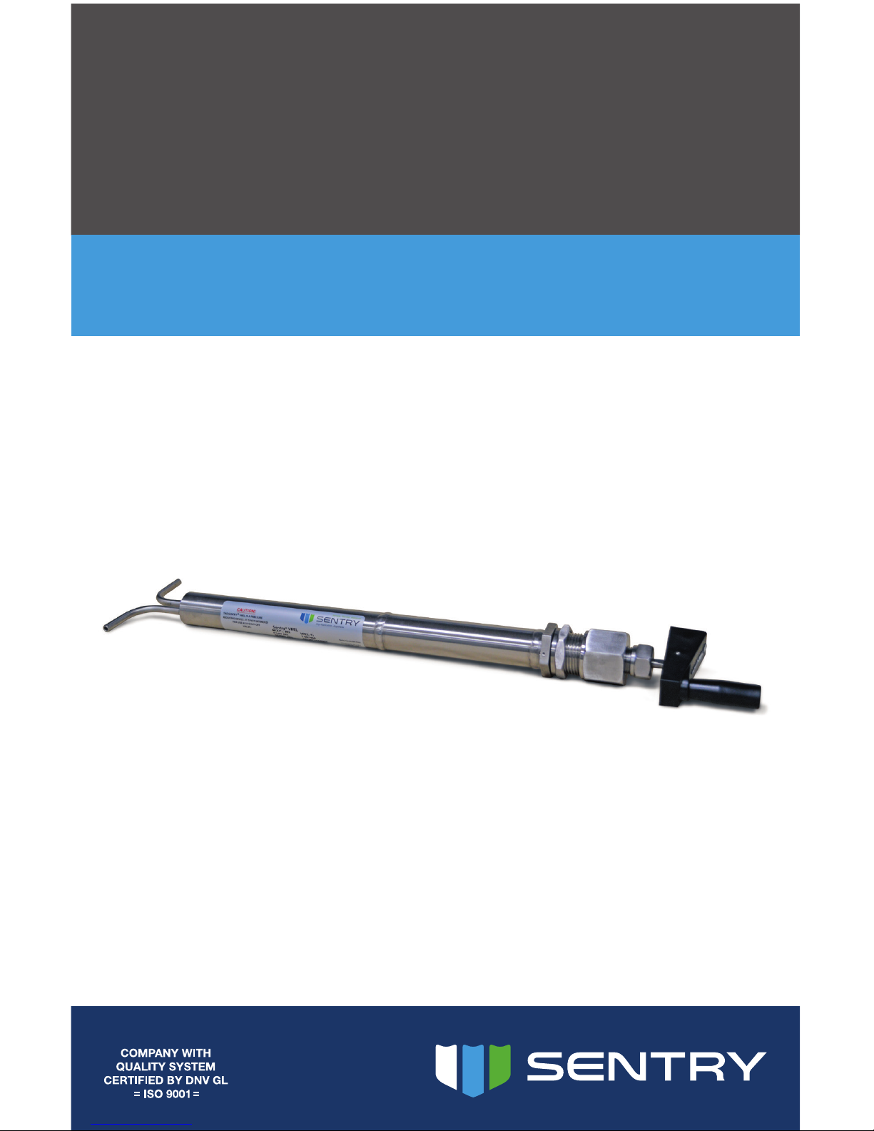
Sentry VREL Control Valve
Pressure Conditioning
S-SW-IOM-00277-15 1-17
Page 2
2 Sentry Equipment Corp
Do not install, maintain, or operate this equipment without reading,
understanding, and following the appropriate Sentry Equipment Corp
instructions. Otherwise, injury, damage, or both may result.
Copyright
© 2016 by Sentry Equipment Corp. All rights reserved. All product and company names
are property of their respective owners. This document contains proprietary information.
No part of this document may be photocopied or reproduced without the prior written
consent of Sentry Equipment Corp.
Limit of Liability
Sentry Equipment Corp, its employees, agents, and the authors and contributors to this
document speci cally disclaim all liabilities and warranties, express or implied (including
warranties of merchantability and tness for a particular purpose), for the accuracy,
currency, completeness, and/or reliability of the information contained herein and/or
for the tness for any particular use and/or for the performance of any material and/or
equipment selected in whole or part with the user of/or in reliance upon information
contained herein. Selection of materials and/or equipment is at the sole risk of the user of
this publication.
Note
The information contained in this document is subject to change without notice.
Table of Contents
Safety Information ......................... 3
General Safety Precautions ................. 4
Overview .................................. 5
Installation. . . . . . . . . . . . . . . . . . . . . . . . . . . . . . . . . 5
Operation .................................. 7
Replacement Parts ......................... 8
Standard Warranty .........................10
Customer Support .......................... 11
Page 3
Sentry VREL Control Valve 3
Safety Information
Please read the entire manual before attempting to unpack, set up, or operate this
product. Pay careful attention to all Warnings, Cautions, and Notes. Failure to do so could
result in serious personal injury and/or equipment damage.
Use of Hazard Information
If multiple hazards exist, the signal word corresponding to the greatest hazard shall be
used.
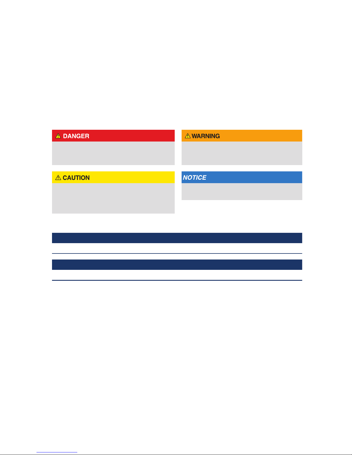
De nitions
DANGER indicates a hazardous situation
which, if not avoided, will result in death or
serious injury.
WARNING indicates a hazardous situation
which, if not avoided, could result in death or
serious injury.
CAUTION, used with the safety alert symbol,
indicates a hazardous situation which, if not
avoided, could result in minor or moderate
injury.
NOTICE is used to address practices not
related to personal injury.
 NOTE
Information that requires special emphasis.
 TIP
Alternate techniques or clarifying information.
SHALL:
This word is understood to be mandatory.
SHOULD:
This word is understood to be advisory.
Page 4
4 Sentry Equipment Corp
General Safety Precautions
Product Selection, Installation, and Use
Improper selection, installation, or use can cause personal injury or property damage. It is solely
the responsibility of users, through their own analysis and testing, to select products suitable
for their speci c application requirements, ensure they are properly maintained, and limit their
use to their intended purpose.
Follow proper local, state, and federal regulations for proper installation and operational
requirements.
Always use caution and common sense when working with any chemical. Read the product
label and Material Safety Data Sheets (MSDS) carefully and follow the instructions exactly.
Potential Equipment Hazards
Hot surfaces! This equipment may have very hot surfaces. If an operator contacts a hot surface,
injury may occur. Use protective clothing to prevent injury. If other equipment comes in contact
with a hot surface, damage to the equipment may occur. Ensure the area around this equipment
is kept clear to prevent this damage from occurring.
High pressures! This equipment may contain uids at very high pressures. Prior to installing,
removing, or maintaining this equipment, ensure that the equipment is isolated from all
connecting piping, the equipment is depressurized, the contents have been drained, and the
equipment is cool.
Page 5

Sentry VREL Control Valve 5
Overview
The Sentry® VREL® Control Valve is a valve specically designed for high-pressure liquid
sampling. Typical applications are for the pressure reduction and ow control of samples
greater than 500 psig (34.5 bar).
The adjustable rod-in-tube design allows for variable pressure drop and ow control of
high-pressure liquid samples. The VREL valve is also cleanable in place.
The VREL valve is an adjustable rod-in-tube pressure reducing device. The pressure of
the incoming sample is reduced as the liquid is forced to travel through the narrow gap
between the tapered rod and the rod opening. Because the reduction in pressure is done
over the entire length of the rod, localized wear is held to a minimum. The result is a very
long service life compared with devices in which the pressure drop is taken over a very
short distance (xed orice, pressure regulator, etc.). Other devices erode frequently
causing friction loss and down time.
With a VREL valve, the ow or pressure drop can be changed while the sample is owing
by adjusting the position of the rods. Turning the handle moves the rods in or out on
the lead screw. If sample ow is blocked, the rods can be fully retracted to allow sample
pressure to ush the dirt through. The sample line never needs to be shut o or the VREL
valve disassembled to accomplish this. This is very important as the operator tries to get
critical samples while boiler pressure is rising or falling during startup or shutdown.
Installation
To ensure the protection provided by this equipment is not impaired, this equipment must not
be installed or used in any manner other than that which is specied in this manual.
Ensure that the VREL valve is installed such that it will not be subject to steam or water sample
temperatures greater than 300˚F. Damage to the VREL valve or downstream equipment may
occur.
The physical dimensions of the VREL valve are shown on the drawing in Figure 4. The VREL
valve can be mounted in any position. The cutouts for panel mounting are shown in
Figure 4. The locating pin ensures correct orientation to connecting tubing. As an
alternative, a U-bolt can be used to hold the body to a panel face or post.
Page 6

6 Sentry Equipment Corp
Installing the VREL valve in a Panel
Isolate the sample line and make sure that it cannot be opened during installation of the VREL
valve. Failure to isolate the sample line could expose personnel to high pressure and/or hot
materials.
1. Drill holes in panel per Panel Cutout diagram in Figure 4.
2. Remove valve handle assembly by unscrewing head nut and pulling assembly out of
body.
3. Remove panel lock nut.
4. Insert body assembly from rear of panel using locating pin to position body.
 NOTE
Do not rely on the locating pin to hold the barrel assembly while tightening the head nut.
5. Install panel locknut. Pull up snug.
6. Insert rods into barrel. Be sure keyway on rod assembly lines up with key inside barrel.
Tighten head nut nger tight.
7. From the backside of the panel, use a wrench on the body nut to hold the body while
further tightening the head nut. It may require considerable torque to get a tight seal
on the metal-to-metal sealing surface inside the head nut.
8. The head nut must be fully tightened before the packing nut can be tightened or
loosened. Tighten packing nut with 15-20 ft-lb (20.3-27.1 Nm) of torque.
Connecting Sample Tubing
Isolate the sample line and make sure that it cannot be opened during installation of the VREL
valve. Failure to isolate the sample line could expose personnel to high pressure and/or hot
materials.
Three types of tube end congurations are available:
Type 1: Plain end – 1/4" tubes with no connections for use with customer supplied
compression ttings.
Type 2: Socket weld – socket weld ttings for customer’s 1/4", 3/8" or 1/2" tubing.
Type 3: 37° Fitting - 37° metal to metal tting for customer’s 1/4" or 3/8" tubing.
Page 7

Sentry VREL Control Valve 7
A VREL valve with Type 1 or Type 3
connectors can be easily disassembled.
Type 2 connectors must be cut out.
For Type 2 and Type 3 connections, the
customer must weld the system tubes
either to the socket weld ttings (Type2),
or to the loose weld adapter (Type3). In
the case of Type 3 connections, be sure
to slide the nut onto the tube before
welding the adapter. See Figure 1.
Operation
During operation, the VREL valve may become hot. Do not touch. Use care not to touch adjacent
hot sample lines.
When starting up a sample line that includes a VREL valve, always be sure that the rods are
fully inserted before opening the sample isolation valve (turn handle clockwise to insert rods).
The VREL valve is not a positive shut-o device. Even when fully closed, approximately 150 cc/
min sample ow through the VREL valve is possible. When the rods are fully inserted, the yoke
bottoms in the barrel. When the rods are fully retracted, the yoke is stopped by the seal.
Do not try to turn the handle by using extra force. The threads will be damaged.
After opening the isolation valve fully, adjust the setting of the VREL valve until the
desired ow is established. Turning the handle clockwise will decrease ow; turning
counterclockwise will increase ow.
Clean in place
Isolate the sample ow before cleaning the VREL valve. When performing this cleaning
operation, the sample pressure is not being reduced by the VREL valve. Failure to isolate the
sample ow could result in serious injury and/or cause damage to pressure-sensitive equipment
downstream from the VREL valve.
Since corrosion products, scale, and other foreign matter may be present in sample lines,
plugging of the VREL valve is possible. To clean, fully retract the rods by turning the handle
in a counter-clockwise direction. Allow the obstruction to clear. Readjust the setting of the
VREL valve until desired ow is established.
CUSTOMER TUBE
WELD ADAPTER
CUSTOMER WELD
CUSTOMER TUBE
NUT
Figure 1. Connection Type 3 – 37° Fittings
Page 8

8 Sentry Equipment Corp
Service
Before servicing, ensure that the sample line is isolated and cannot be opened during this
service. This is necessary to prevent exposure to high pressure and/or hot materials. Allow the
VREL valve to cool to a comfortable touch prior to commencing service.
No normal maintenance is required. Replacement parts available are listed below.
Replacement Parts
Part Number Item
6-02302C VREL Valve Seal Kit (Figure 2) (includes thrust washer, spring
seal & backup washer)
6-02302E Valve Handle & Rod Assembly (Figure 3)
– includes both 6-02302A and 6-02303A
6-02302A Valve Handle Assembly Only (Figure 3)
6-02303A Tapered Rod & Nut Assembly Only (Figure 3)
6-04605A VREL Swivel Handle
Figure 2. 6-02302C – VREL Seal Kit
Thrust Washer
Spring Seal & Backup
Bushing
Ratings
Wetted materials: 316 Stainless Steel
Weight: 4 lbs
Pressure: 5000 psig at 300°F
(345 barg at 149°C)
Page 9

Sentry VREL Control Valve 9
Figure 3. 6-02302E – Valve Handle & Rod Assembly
6-02303A
Rod & Nut
6-02302A
Valve Handle Assembly
Figure 4. VREL
4" [102mm]
REF.
14 1/8" [359mm]
REF.
19 9/16" [497mm]
REF.
Alignment Pin
Body Nut
Panel Lock Nut
1/4" max panel thk
12 7/16"
Removal Clearance Required
4 5/16"
5 5/16"
15/16"
Ø 5/16"
Ø 1 1/4"
Plain End
37˚ Fitting Socket Weld
Panel Cutout
Page 10

10 Sentry Equipment Corp
Standard Warranty
Sentry Equipment Corp (“Seller”) warrants products manufactured by it and supplied
hereunder (“Products”) to be free from defects in workmanship and, to the extent
materials are selected by Seller, to be free from defects in materials, in each case for a
period as de ned in the table below:
Brand Product Line Warranty Period
Sentry® Steam & Water Sampling Products and Systems
Solid & Powder Sampling Products and Systems
Gas Sampling Products and Systems
Liquid & Slurry Sampling Products and Systems
Pipeline Integrity Products
Eighteen months from
date of shipment or
twelve months from
startup (whichever
occurs rst)
Waters
Equipment
Steam & Water Sampling Products and Systems Twelve months from
date of shipment
To view the full warranty, go to
www.sentry-equip.com/warranty.
Page 11

Sentry VREL Control Valve 11
Customer Support
With proven sampling expertise since 1924, Sentry products and services provide business
operations the critical insights to optimize process control and product quality. We deliver
true representative sampling and analysis techniques to customers around the globe,
empowering them to accurately monitor and measure processes for improved production
effi ciency, output, and safety. Standing behind our commitments, we are determined to
tackle any application, anywhere.
We know that running an effi cient operation isn’t easy. It requires thorough, careful
analysis of controlled, real-time data achieved through reliable, accurate, and repeatable
process monitoring and measuring. By e ectively conditioning, sampling, and measuring
gas, liquid, slurry, powder, solids, steam, or water within their production environments,
our customers obtain the critical insights they need to control and optimize their
processes.
Yet, controlling your processes also means reliable customer support throughout the life
cycle of your equipment.
Customer Service—General information, warranty claims, order management.
Installation Service—For systems that require specialized expertise upon installation.
Technical Support—Troubleshooting, training, and technical manuals.
Field Service & Retro ts—When a problem needs immediate attention.
Replacements Parts & Consumables—Order your replacement parts and consumables.
Sentry ProShield Services—Select from four ProShield Guardian service plans
providing di erent levels of support to protect your large system investments with
regularly scheduled maintenance.
To learn more, go to
www.sentry-equip.com/support.
Page 12

sentry-equip.com
966 Blue Ribbon Circle North, Oconomowoc, WI 53066 U.S.A. | +1-262-567-7256 | support@sentry-equip.com
Serving customers
in more than 50 countries
across six continents worldwide.
 Loading...