

Sentry Voyager 12V 60A,Voyager 12V 90A,Voyager 24V 60A,Voyager 24V 100A,Voyager 24V 40A Installation & Operation Manual

MARINE BATTERY CHARGERS
Voyager Elite Series
Installation/ Operation
Linear Devices Corporation
dba Sentry
11126 Air Park Rd, Suite G
Ashland, VA 23005
December 2017
www.sentrychargers.com
Phone: 804-368-8428
Fax: 804-368-8438

2
Table of Contents
Safety Precautions
3-4
Serial Number
4
Model Number
5
General Instructions
5
Installation Instructions
6
Connection Details
7-9
AC Cables and Circuit Breaker Sizing
10
DC Cables and Fuses
11-12
Setting Charging Curve and Battery Types
12-15
Operation of Battery Temp Sensor
16
LED Display Indicators
17
Mode and Display Operation
18
Fault Indicators and Description
19
Technical Specifications
20-22
Dimensions
23
Warranty
24

3
SAFETY PRECAUTIONS
TO PREVENT ANY RISK OF ELECTRIC SHOCK OR FIRE, READ THIS MANUAL
CAREFULLY BEFORE INSTALLING THE EQUIPMENT.
This equipment is not designed for use by people (including children) with diminished
physical, sensory or mental capacities, or people without experience or knowledge of
such equipment, unless they have received prior instruction in the use of the equipment
from a person responsible for their safety or are under the supervision of such a person.
Ensure that children are supervised in order to prevent them playing with the device.
Warning: This equipment contains components that may cause electric arcs or sparks,
when connecting cables. To prevent any risk of fire or explosion, do not install this
equipment close to flammable materials, liquids or gases.
Installation precautions
To prevent any risk of irreversible damage to the equipment, ensure that you comply
with the following recommendations.
• This device must not be installed close to a heat source or any
flammable liquids or gases such as a gas engine room.
• It must not be installed in an airtight or poorly-ventilated
compartment.
• The ventilation inlets must not be obstructed.
• Clearance of at least 4” (10 cm) must be allowed around the housing to
guarantee adequate circulation.
• This device must not be exposed to running water, water spray and dust of any
kind.
• We recommend securing the device in a vertical position, with the cable outlet
pointing downwards.
• You are prohibited from making mechanical alterations to the housing,
including making additional holes, for example.
Connection Precautions
To prevent any risk of electric shock or irreversible damage to the equipment,
you should comply strictly with the following recommendations.
• The installation to which this device is connected must comply with any
applicable regulations such as ABYC.
• This device is designed to be connected to 220-240V 50/60Hz or 100-
120V 60Hz single phase circuits. 115V / 230V selection is automatic.
220-240V only for 24V, 80A, 100A version.
• The main power line must utilize a circuit breaker, to Protect individuals
against electric shocks. Refer to the device’s electrical specifications to select
the size and type of circuit breaker.
Prior to main power connection, the cable gland in the packaging must be assembled and

4
correctly attached to the housing (using the nut provided), in the hole designed for this
purpose.
For safety reasons, the device’s EARTH Ground terminal (PE “Protective Earth” terminal),
must be connected to the system’s physical earth ground (yellow & green wire of the
main power). Refer to the wiring diagram for more information.
To prevent wire or terminal heating, ensure that the cable size is correct and the
connectors are properly tightened.
WARNING: This device is not Protected against battery polarity reversals. A battery
connection error automatically causes the battery fuses to blow as well as irreversible
damage to the circuit board.
Operational safety precautions
To prevent any risk of electric shock on activation or during operation, the Protective
cover must be correctly positioned and screwed into the housing.
This device complies with the applicable regulations governing transmitted interference
and immunity from external disturbances (see EMC paragraph in the Technical
specifications section).
When in operation, take particular care that this device is not subjected to conducted or
radiated interference at levels higher than the legal limits otherwise malfunctions may
occur (e.g.: device too close to a powerful transmitter).
This device transmits conducted and radiated interference at levels that comply with the
applicable regulations. Ensure that other sensitive equipment used in the vicinity is
compatible with this device otherwise malfunctions may occur.
Charger serial number
The serial number appears on the data plate label on one side of the device. This
number is aligned vertically and comprises a first number indicating the year of
manufacture (e.g.: 12 for 2012), a letter indicating the month of manufacture (e.g.: C for
the month of March).
Important note about charging curves
It is important to note that the use of an incorrect charging cycle for the
battery type may extensively impair or even damage the battery and/or charger.
This is particularly true for cycles where the charge voltages are higher than the
levels recommended by the battery manufacturers.
Example: A serious risk of overheating the batteries and releasing gases that are harmful
to users’ health or could cause an explosion.

5
Curve no. 9 is compatible with a LiFeSo4 battery provided that the battery is equipped
with BMS-type battery Protection (Battery Management System) within the actual
battery. In this case, refer to the battery manufacturer’s recommendations for the
choice of charging cycle.
GENERAL INSTRUCTIONS
Maintenance precautions
To prevent any risk of electric shock during maintenance operations, ensure that the
following recommendations are studied carefully before performing any maintenance
on the device:
• All maintenance operations must only be carried out by a suitably
qualified technician.
• In the event of damage to the main power and/or batteries, these may only be
replaced by a qualified person, to avoid any danger.
• The main power supply must be disconnected (cable or
switch).
• The -DC or -BAT supply on the battery must also be disconnected to prevent
any transfer of power.
• To allow the high voltage capacitors to discharge (on the circuit board), wait
for 5 minutes before carrying out any work inside the housing.
• The fuses must be replaced by fuses with strictly identical characteristics and
performance levels.
Model Number
The model number can be determined by the following code:
SVE = Sentry Voyager Elite series
12 or 24 = DC Voltage Output
20, 40, 60… = DC Amp Output
/3 = 3 battery banks
X = 115/230vac or C = 230vac only
J = 50/60 Hz
CONTENTS OF THE BOX
RECEIPT OF THE PRODUCT
Contents of the packaging
The charger.
The user manual.
The main power cable gland and mounting nut (to be installed

6
on the housing prior to connection).
The battery temperature sensor (24V100A version only)
Verify
Verify the Product’s data plate label, attached to one side of the Product, to ensure that
the technical details actually meet your needs (main supply voltage, charger capacity,
etc.).
INSTALLATION INSTRUCTIONS
The charger is attached using 4 x #8 (4mm Ø) screws (not supplied), to a secure
mounting frame or wall.
Ideally, the charger should be in a vertical position, with the cable outlet pointing
downwards. Clearance of at least 4” (10 cm) must be allowed around the device to
guarantee optimum convection, in particular along the sides allowing the air needed
for ventilation to flow in and out.
The circulation and convection direction of the air inside the charger is from right to left,
viewed from the front of the Product.
CONNECTIONS
Ventilation direction
Warm ←←← Cool
CONNECTIONS
To gain access to the charger’s connections, the front cover must be removed. To do
this, simply unscrew the screw on the front cover. The cover is removed by rotating it.
Prior to making connections, the main power cable gland must be positioned and
attached to the housing in the hole designed for this purpose (hole on the left, when
viewed from the front of the charger).
The plastic nut supplied with the cable gland allows it to be attached to the housing.
This nut is positioned on the inside of the housing. Ensure the correct tightening torque
is applied.
7
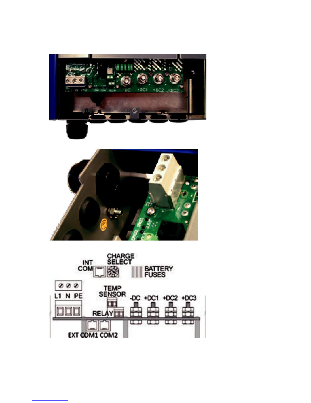
CONNECTION DETAILS

8
Marking
Description
L1
AC main, 8 AWG (10mm2) max (wire color code: brown or
black)
N/L2
AC neutral or L2, 8 AWG (10mm2) max (wire color code: blue,
white or red)
PE (Ground)
AC ground, 8 AWG (10mm2) max (wire color code: green &
yellow or green)
-DC
Battery negative (common), pin M8 (wire color code: black)
+ DC1
Main battery positive, pin M8 (wire code: red)
+ DC2
Auxiliary battery 2 positive, pin M8 (wire color code: red)
+ DC3
Auxiliary battery 3 positive, pin M8 (wire color code: red)
CHARGE
SELECT
Charge curve and battery charging mode selector, 10 positions
(from 0 to 9) (refer to curve settings p14)
BATTERY FUSES
Battery Protection fuses (on the –DC supply)
EXT COM 1
External communication bus (CAN bus)
(for an external digital display or communication between
chargers)
EXT COM 2
External communication bus (CAN bus)
(for an external digital display or communication between
chargers)
INT CoM
Communication bus for a digital display built into the charger
TEMP SENSOR
Battery temperature sensor (2 non-polarized wires, no
polarity)
Connect to the positive terminal of the main battery
RELAY
Dry alarm contact
 Loading...