

Page 1

TURBO HD
1080P Dome Camera
User Manual
Regulato ry In formaon
FCC I nformaon
FCC compliance: This equipmen t has been
teste d and found to comply with the limits for a
digita l device, pursuan t to part 15 of the FC C
Rules. Thes e limits ar e designed to pr ovide
reasonable p rotecon against harm ful
int erference whe n the equipme nt is oper ated in
a comme rcial en vironme nt. This equipmen t
gen erates , uses, a nd can radia te radio
frequency energ y and, if not installed and used
in acco rdance with the instrucon manual, may
cause harm ful interfere nce to radio
communicaons. Oper aon of this equipment in
a residenal a rea is likely to c ause harmful
int erference in which cas e the user will be
requ
ire d to corre ct the interfe rence at his o wn
expense.
FCC Condions
This device complies with part 1 5 of the FCC
Rul es. Opera on is subject to t he followi ng two
condions:
1. This d evice may not cause har mful
int erference.
2. This d evice mus t accept any in terference
recei ved, includin g inter ferenc e that may
cause undesired oper aon.
EU Conformity Statement
upon the purchase of equivalent new equipment,
or dispose of i t at designated collection points.
For more information see:
www.recycle this.info.
2006/66/EC (baery dir ecve):
This product co ntains a ba ery that
cannot be disposed o f as unsorted
municipal waste i n the European
Union.
See the product document aon for specific
bae ry info rmaon. The b aery is mar ked with
this sy mbol, which m ay include le ering to
indic ate cadmium (Cd), lea d (Pb), or mercur y (Hg).
2012/19/EU (WEEE direcve):
Products marke d with this symbol
cannot be disposed o f as unsorted
municipal waste in the European
Union. For proper recy cling, return
this product to your local supplier
This product and - i f applicable - the
supplie d accessories too are mar ked
wit h "CE" and comply the refore with
the applicable harmonized Eur opean
standard s listed unde
r the L ow Volta ge Direcv e
2006/95/EC, the EMC Direcve 2004/108/EC ,
the RoHS Direcve 2011/65/EU.
Thank you fo r purchasing our product. If there
are a ny quesons, or r equests, please do not
hes itate to c ontact the dea ler.
This manual ma y contai n severa l technical
incorrect places or prin ng errors, and the
con tent is subject to chang e without noce.
The updat es will be added t o the new vers ion of
this manual. We will readily improv e or update
the products o r procedures described in the
manual.
DISCLAIMER STATEMENT
Underwriters Labor atories Inc. (”UL” has not)
teste d the performance or reliability of the
security or signaling aspects of this p roduct.
UL has only t ested for fir e, shock or casual ty
hazard s as outlined in U l’s Standard(s) fo r Sa
fety,
UL60950-1. UL C erficao n does not cove r the
performance or reliability o f the security or
signaling a spects of this pr oduct. UL MAKES NO
REPRESENTATIONS, WARRANTIES O R
CERTIFICATIONS WHATSOEVER REGARDING
0100001041016
THE PERFORMANCE OR RELIABILITY O F ANY
SECURITY O R SIGNALING RELATED FUNCTIONS
OF THIS PR ODUCT.
1.2 Ove rview
1.2.1 Ove rview o f Type I Dome Camera
1.2.2 Ove rview o f Type Dome Camera
II
1 Introducon
1.1 Product Features
This camera adopts ne w generaon sensor with
high sensivity and advanced circuit board design
technology. It possesses the fea tures of high
resoluon, low distoron, and low noise, e tc. It is
ext remely suitable for superv isory system and
image processing s ystem.
The main feat ures are a s follows:
High performance CMOS sensor and high
resoluon bring high-quality imag e;
Low illuminaon;
Support I R cut filter w ith auto switch;
OSD m enu, paramet ers are co nfigurable;
Support auto white balance, auto g ain control,
electronic shuer c ontro l and internal
synchroniz aon;
SMART IR mode;
Unit transmission co ntrol;
Adv anced 3-ax is design meets diffe rent
ins tallaon requi rements.
Please make s ure tha t the device in the pack age
is in g ood condion and all the assembly parts
are i ncluded.
Make sur e that al l the relate d equipment is
power -off during the in stallaon.
Check t he spec ificao n of the products fo r the
installa on environment .
Check w hether th e power supply i s matched
wit h your power output t o avoid damage .
Please make s ure the w all is str ong enough to
withstand thre e mes the weight of the camera
and the mounng.
If the wa ll is the cement w all, you need t o insert
expansio n screws befo re you insta ll the came ra.
If the wall i s the wooden wall, you ca n use
self-tappi ng screw to se cure the camer a.
If the pr oduct does not funcon properly,
please con tact your dealer or the nearest
ser vice center. Do not di sassemble the c amera
for re pair or maintenance b y yourself.
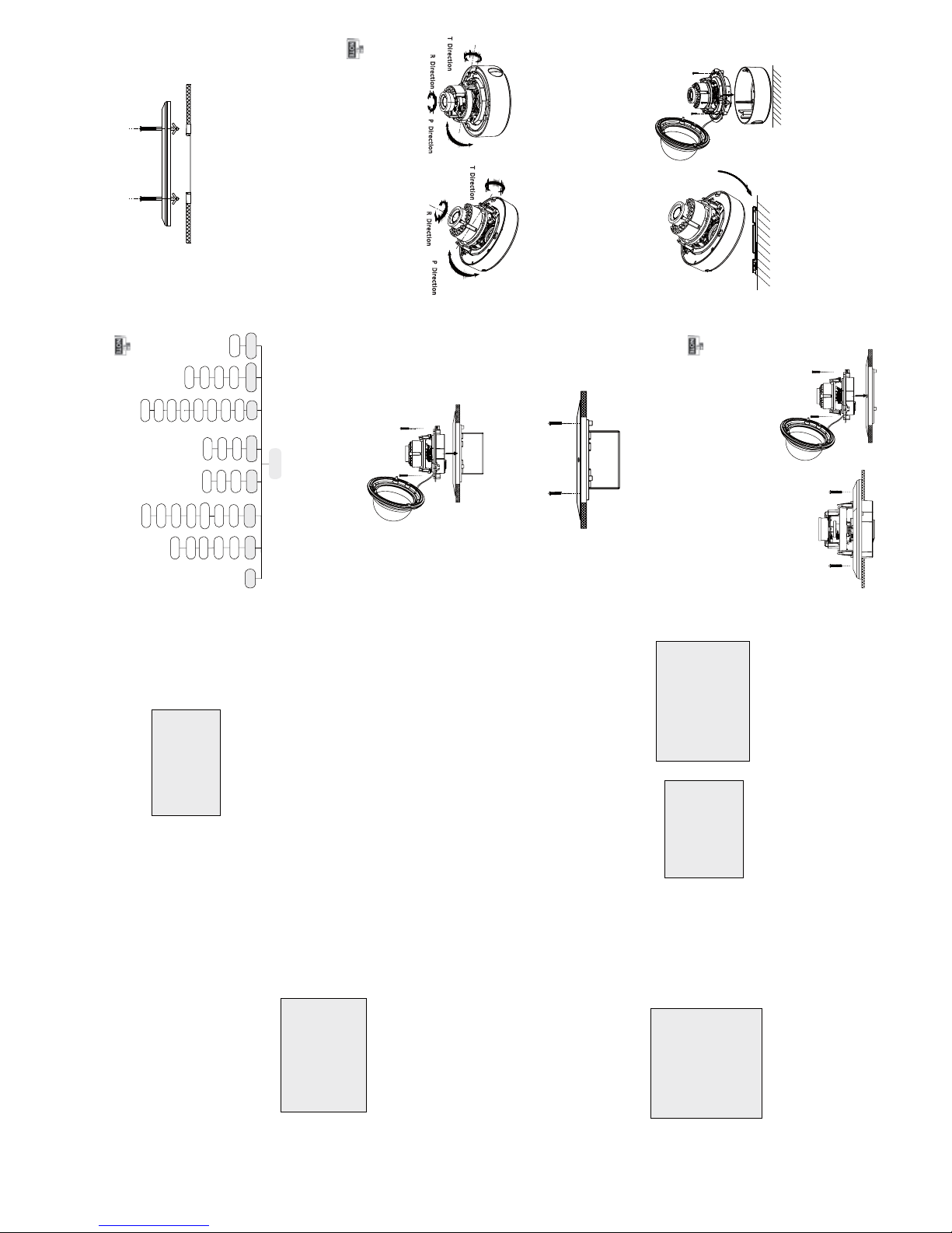
2.1 Ceiling Mounng
Ste ps:
1.Drill th e screw holes and the cabl e hole on the
ceiling acco rding to the sup plied drill t emplate.
Figur e 2-1 The D rill Template
2 Loosen the screws o n the bubble of type 1
.
camera / rotate t he bubble of ty pe2 camera t o
remove the bubble and the black liner.
Figure 2-2 Remove the Bubble
For p roper recy cling, retur n the baer y to your
supplier or to a designa ted collecon point. F or
more informa on see: www.recyclethis.info .
2 Installaon
Befor e you start :
Figure 1 -1 Over view of Type I Dome C amera
Figure 1 -2 Over view of Type Dome CameraII
Type I:
Type I :I
Type I :I
Type I:
Black Liner
Bubble
Powe r Cable
HD Video Cable
Lens
Base plate
Back Box
Lens
Bubble
Black Liner
Power Cabl e
HD Video Cable
Page 2
Ste ps:
1.Drill the screw holes and the cable hole in the
ceiling according to the supplied drill temp lat e.
2.Scre w the bolts through the mount by aligning
with the 2 bolt holes. Fit the t oggles onto the bolts.
3.Push the two tog gle bolts through the t wo screw
holes on the ceiling. Rotate the bo lt ll th e tog gle
holds the ceiling ghtly.
2.2 In-ceiling Mounng
Figure 2 -5 Insta ll the Mount
Figure 2 -6 Fix the Camera to the M ount
Figure 2 -8 Fix the Camera to the G ang Box
5. Repe at steps 6- 8 of the Ceiling M ounn g secon
to co mpl ete the i nstallaon.
3.Route and connect the corresponding cables.
4.Fix the camera to the in-ceiling mount with the
supplied screws.
3.
Aach the back box of type 1 camera /base plate
of type2 camera to the ceiling and secure them
with supplied self-tapping scre ws.
4.Route th e cables through the cable h ole.
5.Align the came ra wi th the back box/base plat e,
and ghte n the set screws to secure the camera
with the back box/base plate.
Figure 2-3 Fix the Camera to the Ceiling
6. Connect the corr esponding cables.
7. Adjust the camera accordin g to the figure below
to get an op mum angle.
8. Fit the black liner on the camera and ght en the
screws on the bubble of type 1 c amera or rotat e the
bubble of type 2 camera to complete.
Figure 2-4 3-axis Adjustment
You need to purchase a n in-ceiling mount separately
if yo u adopt in-celling mounng.
2.3 In-ceiling Mounng
in-ceiling mounng with gang box is supported by
the both types of camera.
1.Repe at step s 2-3 of the In- ceiling Mounng
secon to secure the i n-ceiling moun t (supplied)
to the gang box.
Figure 2 -7 Inst all t he Mount
2.Route and connect the corresponding cables.
3.Align the camera wit h the gang box, an d ghte n
the screws to secur e the c amera with the gang box..
4. Repe at step s 6-8 of the Ceilin g Mounng secon
to co mplet e the ins tal la on.
Type I:
Type I :IType I :IType I :I
0 ~75° °
0 ~355° °
0 ~355° °
P Dire ction
R
Dir
e
ctio n
T
Dir
ec
ti
o
n
Type I:
0°~355°
0 ~75° °
0 ~340° °
T
D
i
re
cti
o
n
R D
i
rec
ti
on
P D
i
rec
ti
on
Type I :I
Type I:
Type I :I
3.1 VID EO.OU T
You can set the frame rate as 25 f ps/30fps .
3.2 DAY/ NIGHT
Color, B/W, AUTO and EXT are selectable for DAY/
NI GHT switches. Under the mode o f the AUT O and
EXT, you ca n set the I R LED as Smart and CDS. If the
IR LED i s selected a s Smart, you c an set the bright-
ness of the I R LED.
3.3.3 AW B
Figure 3 -2 D AY/NIGHT
Figure 3-3 AW B
SPECIAL
1. PRIVACY ZONE
2. MOTION
3. HLC
4. RETURN RET
Figure 3 -4 SPE CIA L
Moon : Set the Moon status a s O N or OFF. Se t
the SENSITIVITY f rom 0 t o 255. Set the ala rm status
as I CON/TRANC E/O FF. Set the hold me from
0 second to 255 seconds.
HL C: HLC supplements the brightness o f the
peripheral ar ea of the i mage. You can s et the mask
val ue and threshold from 0 to 255.
Privacy zone: Select a PRIVACY a rea. Se t the
MASK PAT a s OFF, GRAY, WHITE or BLA CK. Se t the
SX/E X/SY/E Y value to define the posion and size
of the area.
DAY/NIGHT
1. MODE AUTO
2. D TO N 63
3. N TO D 63
4. DELAY TIME 20
5. RETURN RET
AWB
1. MODE AUTO
2. R-G GAIN 255
3. B-G GAIN 151
4. RETURN RET
Auto, User, Push , 8000k, 6000k, 4200k and 3000k
are sel ectab le fo r AW B. Under th e mode of A UTO,
you need t o set the R-G/B-G Gain and t o select an
indoor/outdoor mode. I f the AW B mode is select
as User, You need to set the R/G /B Gain manually.
3.3.4 AE
You can set the A E mode as HOLD, D C and ES C.
: Brightnes s refers to the brigh tnessBrightne ss
of the image.
: Shue r denotes the speed of the s huer.Shuer
You can set the shuer a s AU TO, 1/25, 1 /30, 1/50,
1/60, 1/100, 1/120, 1/250, 1/500, 1/1k, 1/3k and
1/10k.
: You can set the flicker status a s 50 HZ /60HZFlicker
to preve nt image flicking.
: BLC base s on the back area to enhance t he
BL C
brightne ss of the whole image. You can set the
BL C gain f rom 0 to 16.
: AGC o pmize s the clarity of image in poorAG C
light scen e. The value of AG C can be set from 1-5.
: LSC c orrects the phenomenon where theLSC
image g ets dar kened or b lurred on the periphery.
3.3.5 SPE CIA L
SYSTEM
1. CAMERA ID
255
2. ID DISP. ON
3. NAME DISP. ON
4. LANGUAGE ENG
5. FACTORY INIT OFF
6. RETURN RET
3.3.7 SY STEM
You can set the camera I D from 0 to 255.
Select the ID display and name display status as
ON/OFF.
Chinese and English are select able for the language
of the menu.
You can rest ore t he ca mera to the d efault by
seng the factory inializaon status a s ON.
3.3.8 EXIT
Exit and Save & exi t are select able.
EFFECT
1. COLOR GAIN 200
2. COLOR HUE 200
3. SHARPNESS 25
4. CONTRAST 150
5. BRIGHT OFF. 1
6. MIRROR ON
7. FLIP ON
8. RETURN RET
Color Gain: Color gain adjust this feature to change
the saturaon of the co lor. You ca n set the value
fro m 0 to 255.
: You can adjust the image H UE fromColor Hue
0 to 71.
: Sharpne ss determine s the amount o fSharpness
det ail that an imaging system can reproduce.
You can set the value from 0 to 255.
: Contra st en hances the diffe rence inContrast
col or and light between parts o f an image .
You can set the value from 0 to 255.
: Bright Off. refers to the brightnessBright Off.
compensa on o f the
image . You can set the bright
compensaon value as 0 or 1 .
: You can set the Mirror status as ON/O FF.Mirror
: You can set the F LIP status as ON/OF F.Flip
3.3.6 EFFEC T
Figure 3-5 EFFE CT
Figure 3-6 SYSTEM
3 Menu Operaon
Figure 3-1 Main Menu
Menu
AE
AWB
DAY&NIGHT
SYSTEM
SPECIAL
EFFECT
DC
ESC
HOLD
FRAME
RATE
AUTO
USER
HOLD
8000K
6000K
COLOR
B/W
AUTO
CAMERA
ID
ID DISP
PRIVACY
ZONE
MOTION
HLC
LANGUAGE
COLOR
GAIN
COLOR
HUE
SHARPNESS
EXIT
VIDEO.OUT
4200K
3200K
CONTRAST
BRIGHT
OFF
MIRROR
FLIP
NAME
DISP
FACTORY
INIT
EXT
PUSH
A coa xia l camera c ont rol ler (purc hase separat ely)
is re quired t o select the menu and adjust the
camera paramete rs.
 Loading...