

Page 1
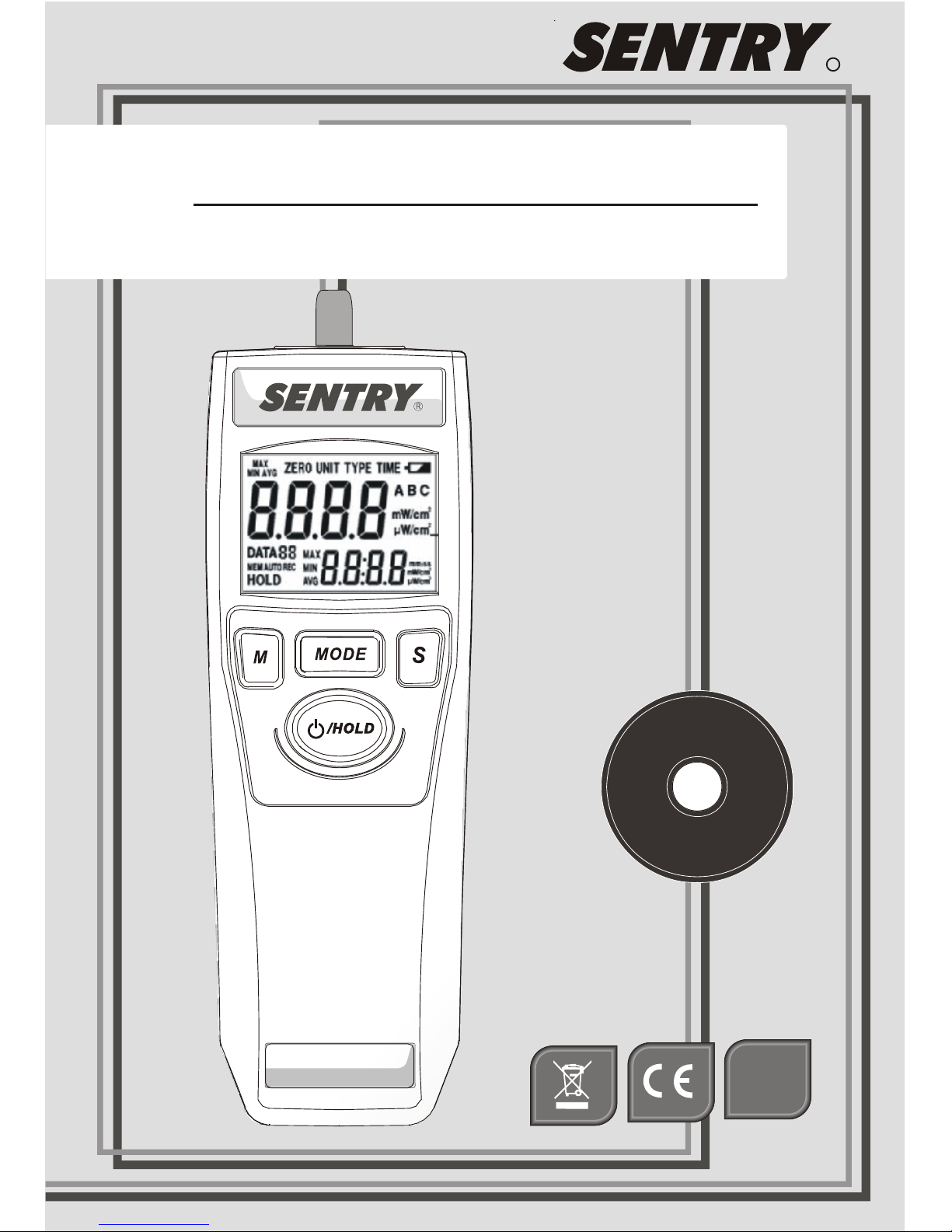
ST-5XX
V
Instruction Manual
R
RoHS
COMPLINT
Page 2

Page 3

V
Instruction Manual
Page 4
Storage for sensor
UV sensor is with extremely precise
structure. Once don’t use it , be sure
it in the dry environment. Manual
for future reference.
Improper use endangers the health of third parties ! It
may also result in damage to the equipment or other
material damage.
Danger when using the equipment
ATTENTION
Page 5

Table Content
1. General Information
2. Features
3. Safety Symbols
4. Specification
6. Operations of Instrument
5-1 Control Panel
5-2 LCD Display
1
1
2
4
5
6
3
Page 6

1
1. General Infor mation
Thank you for purchasing the ultraviolet meter.
Read through this instruction manual before
operating the unit. Please also store and retain
this instruction manual for future reference.
Socket of tripod mounting.
High and Low measurements range in a unit
2 2
mW/cm or μW/ cm .
20 points memory.
Automatic measuring.
Low battery indicator.
Operation with 9V battery.
2. Features
The UV-Meter is a mobile, hand-held device for
measuring UV irradiation.
Backlit LCD and 4 Digits dual display.
Magnetic mount.
Page 7

2
3. Safety Symbols
Indicates CE conformity
The device may not be disposed with the
trash. It promotes the re-use recycling
and other forms of recovery of u s ed
materials and components, and improves
the environmental performance of all
operators ( manufacturers, traders a nd
treatment facilities) involved in the lif e
cycle of products. Dispose of the pr o duct
appropriately in accordance wit h t he
regulations in force in your Co untry.
Page 8

4. Specification
Over Range Indication ' -HI- '
Zero Adjust
Auto Record
Sample Time
Display
Memory
Operation
Temperature
0~50℃(32 ~122℉),10~90%RH
Battery Type
Dimensions
Accessory
Weight
)140 x 49 x 29 mm( 51x 1 .93 x 1.14i nch
.
5
Approx. 90g without battery and detector.
9V Battery , UV sensor probe ,
Instruction manual.
Yes
Yes
Approx. 0.3 sec
Backlit LCD and Dual Display
20 points and 1 for interval time
9V (006P,IEC6F22,NEDA1604)
3
Page 9

4
5-1 Control Panel
1.LCD Display
5.Select Button
4.Power On/Off
and Hold Button
2.Memory button
3.Mode button
1.
2.
3.
4.
5.
Page 10

5
5-2 LCD Display
1. Main Functions
2. Primary Reading
3. Data Log
4. Auto Mode
5. Memory Review
6. Data Hold
7. Record
8. MAX/MIN/AVG
9. Secondary Reading
10.Time Unit
11.Unit
12.UV Type
13.Low Battery
11
Page 11

6
6. Operations of Instrument
Power On
Press button and hold for 2 seconds.
Release the button after power on. All
symbols of LCD will appear for 1 second.
Power Off
Press button and hold for 2 seconds.
All symbols of LCD will appear and shut down
after releasing button.
Measurement Value
The primary reading always displays value of
measuring. The secondary reading displays the
outcomes of the advanced functions or data
recording.
Ho ld
/
Ho ld
/
Ho ld
/
Ho ld
/
Page 12

7
Main Function
Press Mode button to choose the main funct i o ns
(MAX/MIN/AVG has several extended programs
as indicated in the diagram, please read t he
following descriptions to know how to press S,
or M buttons to move to next level!)
Main Function diagram
MAX
MIN AVG
ZERO
TYPE
UNIT
TIME
MODE
/ HOLD Data Hold
M
Data Review
M
S
None
MAX
MIN
AVG
/ HOLD
Data Store
Auto Record
Hold For 2 Second
Ho ld
/
H o l d 2 S ec on d
Page 13

8
Max/Min/Avg Measuring Function
There are 4 modes of the measuring function.
Press S button to change the mode of measuring:
None → Max → Min → Avg.
Data Hold
Press button, the value a t Secondary
Display will be held and the LCD wi ll sh ow
HOLD symbol. To cancel hold mode, p ress the
button again.
Data Review
Press M button during the hold mode , it will
get into the data memory review mode. The LCD
will show MEM symbol.
Press S button to review data 0 to 20. Data 0 is
always stored the interval time after auto
recording activated. If the data are automatically
recorded, the AUTO symbol appears next to
MEM during the review.
Ho ld
/
MAX
MIN AVG
Page 14

9
Data Store
Normal
Press M button to store the current measurement
displayed at Primary Display. The flashing
DATA(01~20) icon becomes steady for 2
seconds, and moves to next storage location.
Auto
If automatically recording is required, press M
button and hold for 2 seconds. The LCD will
show AUTO symbol next to REC symbol. As
soon as it reaches 20 data, the system will turn
off.
1. Irradiation intensity
2. Maximum, Minimum, Average or none
3. Unit
To cancel auto record mode, press M button
again.
The following record contents will be stored:
Page 15

10
Zero Adjust
Cover the sensor and press S button to zero
adjust. The Secondary Display will display
adjust value*. Press S button again and hold for
1 second to clear the adjust value.
*When the adjust value is over the range. The Secondary
display will display “-Err”. Please follow the zero adjust
step and do it again, or contact the distributor.
Memory Clear
In Zero Mode, press M button to clear data 0 to
20.
Unit Function
2
Press S button to change the unit, μ W/c m or
2
mW/cm
Type Function
(Only for wide range models, which cover two or more
sensors.)
Press S button to set UV sensor spectrum.
ZERO
TYPE
UNIT
TYPE
Page 16

11
Time Function
Press S button to set the interval time of auto
recording.
This function allows to set 9 different time
intervals by pressing S button.
The 9 time intervals are: 1, 2, 5, 10, 30 second or
1, 3, 5, 10 minutes.
TIME
Page 17

12
Maintenance
Clean the housing: Use soap and water on a
damp sponge or soft cloth. Care should be taken
to prevent any liquids or moisture to get inside
the unit.
When the battery is low, the battery symbol will
display.
Page 18

Specification
280 320 360 380 400 420
UVAB SENSOR
Sensor designation UVAB
Spectrum range 280~400
Calibration point 365nm
Temperature range
Accuracy( °C)
Units/multi-ranges
nm
0° ~50°C
23±5 ±4% ±1 digit
Surface sensor
PA05-0UVAB513-01
Low illumination
High illumination
2 2
W/ c m W/ c m0.01 m ~40.00 m
2 2
1 μW / c m μW/ c m~9999
Note: Press Mode" key to enter Unit selection mode."
0
20
40
60
80
100
Relative Spe ctr al Sensitivity(% )
ATTENTION
Th e s e nso r s a re o nl y s uit a bl e f or s hor t t er m
m e a s u r e m e nt i n a s p l a sh - p r o o f enviro n m e n t , a s
oth erwis e p remat ure agi ng and ther mal des truct ion
of the sen sor will occur. The housing temp erature
must never exc eed 5 0°C!
D i m e n s io ns
Ø = 3 5 mm
H = 25 .5 mm
Wavele ngt h λ ( nm)
Ø
H
Page 19

Extendable Wand
2
3
4
upper case
self-tappi ng
screws
lower case
senser
1
2
3
4
X5
X1
X1
X1
(A)
Note:
Recommend not to assemble and disassemble
too many time to avoid the wear of screw holes .
(B)
1
Page 20

ST 512 . Version-01 07/SEP.
3F, No.122, Sec.1, Sanmin Road,
Ban-Ciao, Taipei 220, Taiwan, R.O.C.
TEL:886-2-2956-8198
FAX:886-2-2956-7662
http://www.sentrytek.com.tw
PA05-0000512-01
 Loading...