

Page 1
™
SENTRY
HOT WATER MODELS S-34 THROUGH S-150
GAS-FIRED CAST-IRON BOILERS FOR NATURAL AND L.P. PROPANE GASES
INSTALLATION AND OPERATING INSTRUCTIONS
CONTENTS . . . . . . . . . . . . . . . . . . . . . . . . . . . . . . . . . . . . . . PAGE
Dimensions . . . . . . . . . . . . . . . . . . . . . . . . . . . . . . . . . . . . . . . . . 2,3
Installation Requirements
Boiler Location . . . . . . . . . . . . . . . . . . . . . . . . . . . . . . . . . . . . . 3
Boiler Foundation. . . . . . . . . . . . . . . . . . . . . . . . . . . . . . . . . . . 3
Chimney Requirements . . . . . . . . . . . . . . . . . . . . . . . . . . . . . . 4
Minimum Clearance . . . . . . . . . . . . . . . . . . . . . . . . . . . . . . . . . 4
Draft Hood . . . . . . . . . . . . . . . . . . . . . . . . . . . . . . . . . . . . . . . . 4
Vent Piping . . . . . . . . . . . . . . . . . . . . . . . . . . . . . . . . . . . . . . . . 4
Vent Damper Installation . . . . . . . . . . . . . . . . . . . . . . . . . . 4,5,6
Gas Piping . . . . . . . . . . . . . . . . . . . . . . . . . . . . . . . . . . . . . . . . 6
Electrical Controls and Wiring . . . . . . . . . . . . . . . . . . . . . . . . . 6
Boiler Water Temperature Control . . . . . . . . . . . . . . . . . . . . 7–9
Multi-zoning . . . . . . . . . . . . . . . . . . . . . . . . . . . . . . . . . . . 10–11
Sequence of Operations . . . . . . . . . . . . . . . . . . . . . . . . . . . . 12
Boiler Room Air Supply and Ventilation . . . . . . . . . . . . . . . . 13
Water Piping at Boiler . . . . . . . . . . . . . . . . . . . . . . . . . . . . . . 13
Operating Instructions
Filling and Venting Water Systems . . . . . . . . . . . . . . . . . . . . 13
Burner Adjustment, Checking Gas Input. . . . . . . . . . . . . . . . 14
Care and Maintenance
General Maintenance . . . . . . . . . . . . . . . . . . . . . . . . . . . . . . . 15
Water Level Check . . . . . . . . . . . . . . . . . . . . . . . . . . . . . . . . . 16
Annual Inspection and Cleaning . . . . . . . . . . . . . . . . . . . . . . 16
Safety Check for Control Systems . . . . . . . . . . . . . . . . . . . . 16
Protection from Freezing/Water Treatment . . . . . . . . . . . . . . 16
Keeping Area Clear . . . . . . . . . . . . . . . . . . . . . . . . . . . . . . . . 16
Troubleshooting Guide . . . . . . . . . . . . . . . . . . . . . . . . . . . . . . . . 17
Replacement Parts . . . . . . . . . . . . . . . . . . . . . . . . . . . . . . . . . . . 18
Appendix A & B . . . . . . . . . . . . . . . . . . . . . . . . . . . . . . . . . . . . . . 18
Appendix C & D & E. . . . . . . . . . . . . . . . . . . . . . . . . . . . . . . . . . 19
READ ALL OF THE FOLLOWING
WARNINGS AND STATEMENTS
INSTALLATION INSTRUCTIONS
The installation must conform to the requirements of the authority
having jurisdiction or, in the absence of such requirements, to the
National Fuel Gas Code, ANSI Z223.1-latest edition or CSA
B149.1 latest edition for natural gas and propane. The installation
must also conform to the additional requirements in this Slant/Fin
Instruction Book.
In addition, where required by the authority having juris dic tion,
the installation must conform to American Society of Mechanical
Engineers Safety Code for Controls and Safety Devices for
Automatically Fired Boilers, No. CSD-1 or CSA B149.1 latest
edition
for natural gas and propane. If there is any conflict
in the above requirements, then the more stringent requirement
will apply.
This boiler, gas piping and accessories must be installed,
connected, serviced and repaired by a trained, experienced
service technician, familiar with all precautions required for gasfired equipment and licensed or otherwise qualified, in
compliance with the authority having jurisdiction.
IMPORTANT
BEFORE READING THE
WARNING
SEE "WARNING" ON PAGE 3
FOR LIQUEFIED PETROLEUM (L.P.)
PROPANE GAS-FIRED BOILERS
WARNING
Heating Contractor
Address
Phone Number
This manual must be left with owner and should be hung
on or adjacent to the boiler for reference.
Boiler Model Number
Boiler Serial Number
Installation Date
Printed in Canada 0713 Publication No. S-41
Part No. 46-0528C Revision B
Page 2
2
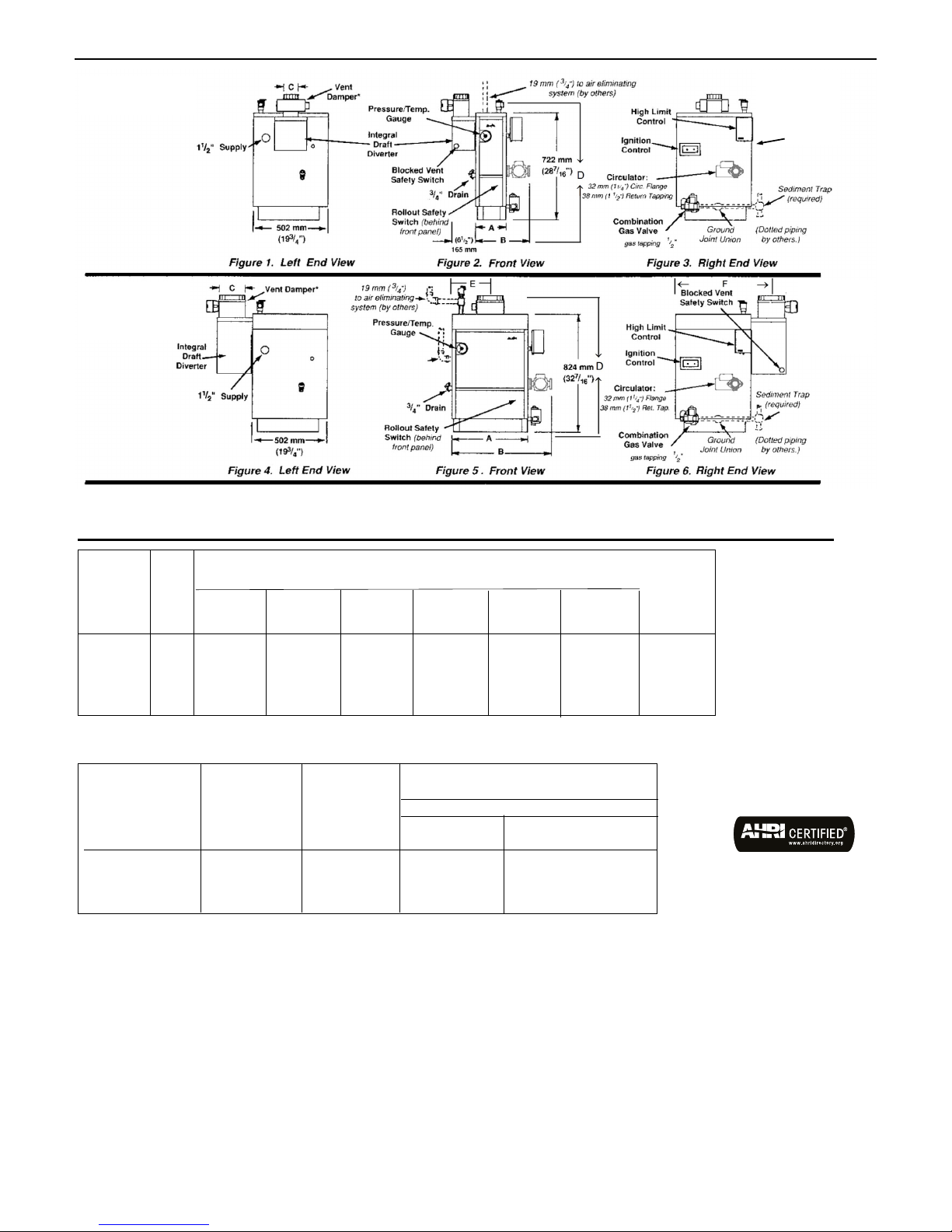
Dimensions
MODEL S-34
Dimensions
MODELS S-60
to S-150
Sentry
Install manual gas main
shutoff valve 1.52 m (5
ft.) above floor, when
required by local code.
Install sediment trap and
connect with ground
joint union. Dotted
piping by installing
contractor.
Install manual gas
main shutoff valve
1.52 m (5 ft.) above
floor, when required
by local code. Install
sediment trap and
connect with ground
joint union. Dotted
piping by installing
contractor.
Note: Height dimension increases by 1-3/4" when comustible floor kit is used.
* Vent damper may be installed horizontally on all models with use of a vent elbow. For more information, see figure 2, page 5.
Approx.
Total Wt.
Boiler No. of Full of
Model Sect.
A B C D E F
Water
mm in. mm in. mm in. mm in. mm in. mm in. kg lb.
S-34 2 206 81/8371 145/81024838 33 –––– 86 190
S-60 3 283 11
S-90 4 359 14
S-120 5 435 17
S-150 6 511 20
Boiler
Model
S-34
1
/8 448 175/8 1024940 37 114 41/2 660 26 113 250
1
/8 524 205/8 1275940 37 140 51/2 648 251/2 141 310
1
/8 600 235/8 1526940 37 191 71/2 635 25 166 365
1
/8 676 265/8 1787940 37 216 81/2 622 241/2 193 425
Orifice
Size
for
Gas Sea
Type Level
Orifice Sizes for High Altitudes
Reduce output 10%
Elevation
610-1220 m 1220-1375 m
(2000-4000 ft) (4000-4500 ft.)
Natural 47 48 49
Propane 56 56 57
S-60 thru S-150
Natural 50 51 51
Propane 57 58 59
Orifice indicated for sea level above are factory installed in boiler unless otherwise specified by the
local authority.
.
CHIMNEY RECOMMENDATIONS
HEIGHT: 4572 mm
(15 ft.) (minimum) from draft hood
skirt to top of chimney. INSIDE
DIAMETER: Same as dimension C (or
larger). NOTE: Larger chimney may
be required if two or more boilers or a
boiler and another appliance are
vented to a single chimney. Size of
Gas Line Connection to Boiler is 13
mm (1/2")
on both Natural and Propane boilers.
Page 3
Sentry
3
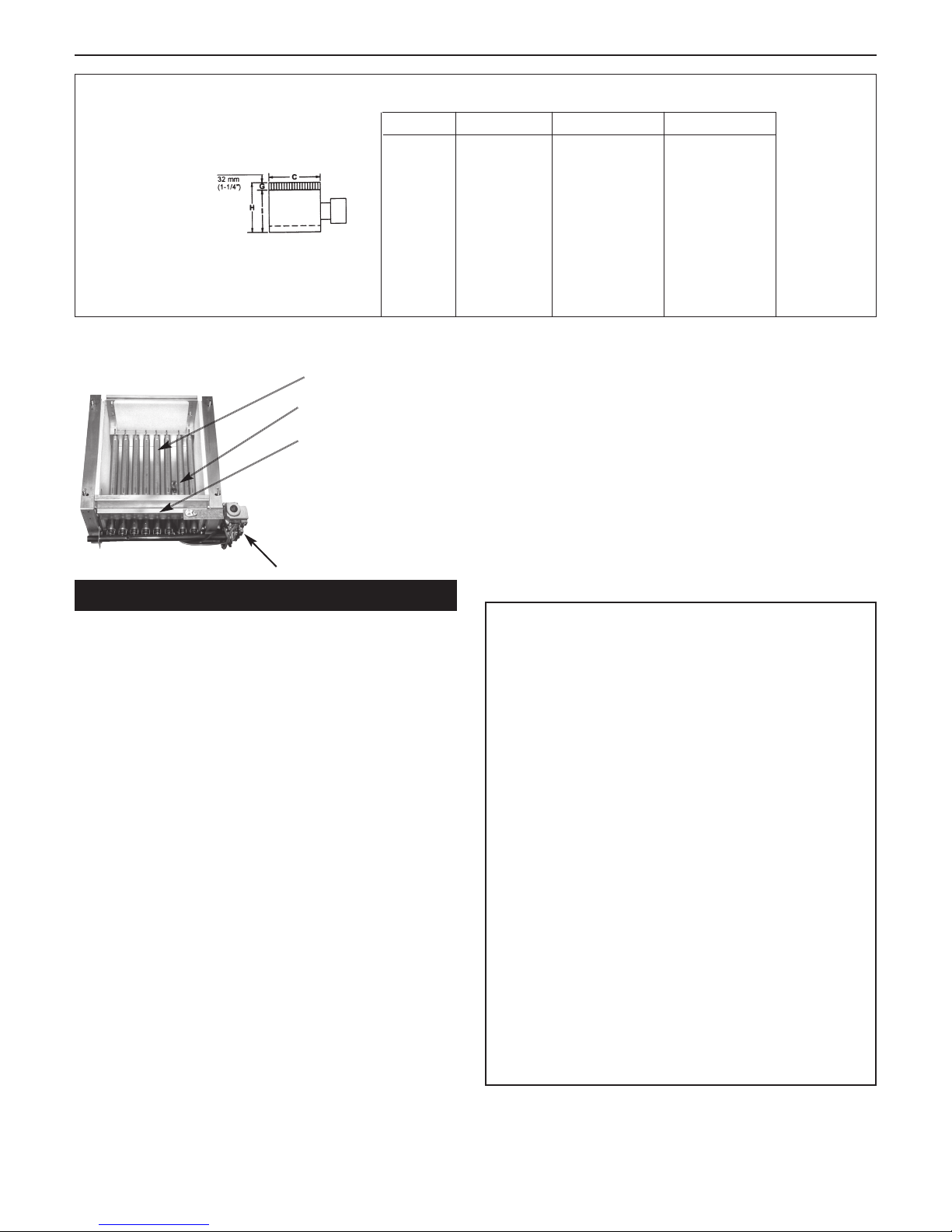
VENT DAMPER DIMENSIONS
Base Assembly
Sentry Boiler
Burners
Pilot
Burner
Access
Door
Field Control (Effikal) Vent Damper
Model # C H I
S34 102mm 152mm 122mm
(4”) (6”) (4-13/16”)
S60 102mm 152mm 122mm
(4”) (6”) (4-13/16”)
S90 127mm 152mm 122mm
(5") (6") (4-13/16")
S120 152mm 165mm 135mm
(6") (6-1/2") (5-5/16")
S150 178mm 179mm 149mm
(7") (7-1/16") (5-7/8")
B. For installation on non-combustible floors only. The
Combustible Floor Kit part number printed on the boiler
rating plate is the only one to be used when installing on
combustible floors. The boiler must not be installed on
carpeting.
C. If boiler is to be located over buried conduit containing
electric wires or telephone cables, consult local codes or
the National Board of Fire Underwriters for specific
requirements.
Gas Valve
INSTALLATION REQUIREMENTS
IMPORTANT: This equipment must be installed in accordance
with the requirements of CSA B149.1 latest edition for natural
gas and propane. Installation Codes for Gas Burning Appliances must conform to requirements of the local gas company, local building codes, and other authorities which have
jurisdiction. Such requirements, where applicable, take precedence over these general instructions. All electrical connections must be in accordance with Canadian Electrical Code
C22.1 Part 1.
This installation must also conform to the additional requirements in this Slant/Fin Instruction Book.
NATURAL GAS-FIRED BOILER LOCATION
Provide a level, solid foundation for the boiler. Location
should be as near as possible to chimney or outside wall so
that the flue pipe from boiler is short and direct.
The location should also be such that the gas ignition system
components are protected from water (dripping, spraying,
rain, etc.) during appliance operation and service (circulator
replacement, condensate trap, control replacement, etc.).
BOILER FOUNDATION
A. Provide a solid, level foundation, capable of supporting
the weight of the boiler filled with water, and extending at
least 51 mm (2") past the jacket on all sides. See dimen-
of boiler, page 2.
sions
WARNING
LIQUEFIED PETROLEUM (L.P.) PROPANE
GAS-FIRED BOILER LOCATION
REQUIRES SPECIAL ATTENTION
Liquefied Petroleum (L.P.) propane gas is heavier than air.
Therefore, propane boilers, piping, valves must NOT be
installed in locations where propane leaking from defective
equipment and piping will “pool” in a basement or other
space below the leak.
A spark or flame from the boiler or other source may ignite
the accumulated propane gas causing an explosion or fire.
Provide a level, solid foundation for the boiler. Location
should be as near the chimney as possible so that the flue
pipe from boiler to chimney is short and direct.
The UNIFORM MECHANICAL CODE may be in effect in
your geographic area
The following precautions are cited by the 1994 UNIFORM
MECHANICAL CODE, section 304.6 or CSA B149.1 latest
edition for natural gas and propane:
“LPG Appliances. Liquefied petroleum gas-burning
appliances shall not be installed in a pit, basement or
similar location where heavier-than-air-gas might collect.
Appliances so fueled shall not be installed in an abovegrade under-floor space or basement unless such location is provided with an approved means for removal of
unburned gas.”
Consult Chapter 5 of
CODE or CSA B149.1 latest edition for propane for design
criteria of the “approved” means for removal of unburned
gas.
the 1994 UNIFORM MECHANICAL
Page 4

SAFETY
KEEP THE BOILER AREA CLEAR AND FREE FROM
COMBUSTIBLE MATERIALS, GASOLINE AND OTHER
FLAMMABLE VAPORS AND LIQUIDS.
VENT PIPING
A. Vent piping installation must be in accordance with the require-
ments of the local gas utility, local building codes and other
authorities having jurisdiction.
B. Boiler vent pipe must be the full diameter of the boiler outlet. See
dimensions, page 2.
C. If more than one appliance vents into a common breeching, the
area of the breeching must be equal to the area of the largest vent
plus 50% of the area of the additional vent areas. Vent connectors
serving appliances vented by natural draft shall not be connected
into any portion of mechanical draft systems operating under positive pressure. Horizontal breeching or vent pipe should be as high
as possible, consistent with codes, so that vertical vents from appliances will have a high rise above draft diverter openings. All horizontal runs must slope upwards not less than 20 mm/m (1/4 inch
per foot) of run. Horizontal portions of the venting system must be
supported to prevent sagging by securing each joint with metal
screws and by providing hanger spaced no greater than 1524 mm
(5 feet apart).
D. Vent or breeching into chimney should not be inserted past the
inside wall of the chimney liner.
E. All venting means should be inspected frequently. See Care and
Maintenance and separate User's Information Manual.
VENT DAMPER INSTALLATION
The vent damper referred to in the following instructions is
the Slant/Fin LTD/LTEE vent damper.
I. This device is design certified by C.S.A. for use ONLY on specific
Slant/Fin gas boiler models. These boilers must also be equipped
with a plate which states that the boiler must or may be used with
a Slant/Fin automatic vent damper device and indicates the proper vent damper model number. This device cannot be used with
a millivolt ignition system.
II. A. INSTALLATION INSTRUCTIONS BEFORE YOU START TO
INSTALL
1. Read this installation manual, the "DANGER" plate attached
to the top of the boiler, the "WARNING" on the wiring diagrams, vent damper carton and operator cover.
2. Perform pre-installation inspection as required by ANSI
specification Z21.66
or CSA B149.1latest edition for nat-
ural gas and propane
.
3. Turn off all electrical power, gas supply and wait for system to
cool (for previously installed boilers).
4. Carefully unpack the unit. DO NOT FORCE IT OPEN OR
CLOSED! Forcing the damper may damage the gear train
and void the warranty.
4
Sentry
CHIMNEY REQUIREMENTS
A. Sentry boilers may be vented into a masonry vitreous tile-lined
chimney or type “B” venting system NOT EXPOSED to the OUTDOORS below the roof line.
Venting and sizing of venting system must be in accordance with
the requirements of the local gas utility, local building codes and
other authorities having jurisdiction.
If a masonry chimney is exposed to the outdoors on one or more
sides below the roof line (exterior chimney), ONE of the following
options apply:
1. Chimney must be re-lined with an approved metallic liner.
When this is done, the chimney will be considered NOT
exposed to the outdoors and the requirements for NONexposed chimneys and/or local codes will apply.
2. If an exposed tile-lined chimney is to be used WITHOUT a
metallic liner, the boiler must first meet the requirements of the
following tables and paragraphs of the National Fuel Gas
Code:
I. For Single Sentry Boiler—Paragraph 11.2.9 and table
11.11.
II. For multiple appliances—Paragraph 11.3.18 and table
11.12 (or 11.13 if applicable).
In addition, all requirements of the local gas utility, local building codes and other authorities having jurisdiction apply.
B. If an existing boiler is removed from a common venting system,
the common venting system may be too large for proper venting
of the remaining appliances connected to the common vent. Follow the test procedure shown in Appendix “A” on page 19 of this
manual to insure proper operation of venting system and appliances.
C. Inspect for proper and tight construction. Any restrictions or
obstructions must be removed. An existing chimney may require
cleaning.
D. Chimney or vent must extend at least 914 mm (3 feet) above any
ridge within 3048 mm(10 feet) of the chimney.
MINIMUM CLEARANCES FOR COMBUSTIBLE
CONSTRUCTIONS
* Allow extra clearance from combustibles for additional venting
A. Minimum boiler clearances shall be as follows:
B. Provide accessibility clearance of 510 mm (24”) on sides requir-
ing servicing and 457 mm (18”) on sides used for passage.
C. All minimum clearances shown above must be met. This may
result in increased values of some minimum clearances in order
to maintain the minimum clearances of others.
D. Clearance from hot water pipes shall be 25 mm (1 inch)**.
** At points where hot water pipes emerge from a floor, wall or ceiling,
the clearance at the opening through the finished floor, wall or ceiling
boards may not be less than 13 mm (1/2 inch). Each such opening
shall be covered with a plate of non combustible material.
SENTRY SERIES
MINIMUM CLEARANCES FOR COMBUSTIBLE
CONSTRUC TION. MINIMUM ALCOVE AND CLOSET
CLEARANCE.
S-34 thru
S-150
Front 152 mm (6”)
Rear 152 mm (6”)
Left Side 152 mm (6”)
Right Side 305 mm (12”)
Top (above boiler) 305 mm (12”)*
Flue Connector 152 mm (6”)
WARNING—DANGER
Once you have begun vent damper installation procedure,
DO NOT restore electric power and gas supply until installation and inspection have been completed (in order to prevent the main burners from operating). DO NOT operate
the boiler until the vent damper harness "FEMALE PLUG" is
plugged into "MALE PLUG" (as described in the installation
instructions), and the vent damper installation and checkout procedures have been completed. Failure to observe
this warning may create a hazardous condition that could
cause an explosion or carbon monoxide poisoning.
Page 5
Sentry
5
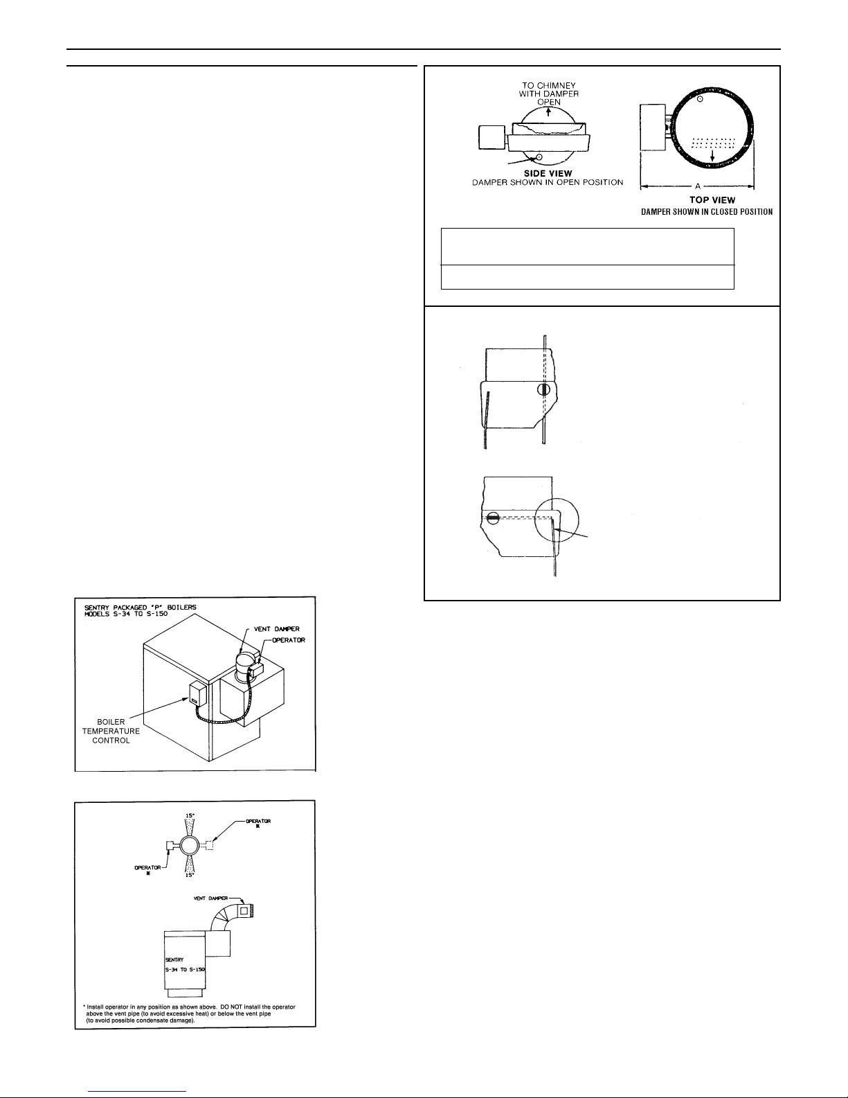
. 5. This device must be installed after the appliance draft hood
(between the draft hood outlet and the connector to the outdoor chimney or vent) as close to the draft hood as practicable, and without modification of the draft hood or the
damper. (See figures 1 and 2.)
6. The inlet size of the vent damper must be the same nominal
trade size as the outlet of the draft hood.
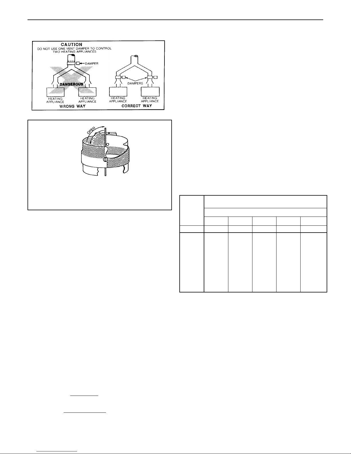
7. This device must be located in a venting system or section of
a venting system so that it serves only the single appliance
for which it is installed. (See fig. 5.)
8. Clearances of not less than 152 mm (6 inches) must be
maintained from combustible materials, with provisions for
access for service.
B. NOW, PROCEED AS FOLLOWS:
1.Separate the vent pipe directly on top of the draft hood or
diverter and place damper in position as shown in figures 1 -
5. The vent damper must be installed so that the damper
position indicator is in a visible location after installation. See
figure 4 for position indicator description. The arrow imprint
on the damper should point in direction of vent gas flow
(towards chimney). Re-assemble the vent piping. Be sure
the vent damper is well seated and fastened with 3 sheet
metal screws. Screws should be no longer than 13 mm (
1
/2
inch). See figure 6.
2. Be sure that undersized vent pipe does not block movement
of damper vane (see figure 4).
3. Boilers that have a vent damper are factory wired with a male
plug.
a) Attach the flexible metallic conduit vent damper harness to
the right hand side of the jacket by passing the free end of
the harness through the 22 mm (
7
/8") diameter hole in the
top of the jacket, and using the BX connector at the free
end of the metallic conduit, fasten to jacket.
22 mm (7/8") DIA.K.O.
FIGURE 3
FIGURE 4
b) Connect "FEMALE PLUG" (free end of vent damper har-
ness) into "MALE PLUG" (see correct wiring diagram for
intermittent pilots).
c) The other end of the flexible metal conduit has a small
molex plug and a 90 degree metal conduit connector.
Route the molex receptacle through the conduit bracket
on the vent damper. Place the harness receptacle into the
damper plug. Securely fasten the harness conduit connector to the conduit bracket by carefully pushing it into
the hole in the bracket.
4. Restore electrical power and turn on gas supply.
C. AFTER INSTALLATION:
1. Operate system through two complete cycles to check for
opening and closing in proper sequence, and proper burner
operation. DAMPER MUST BE IN OPEN POSITION WHEN
BOILER MAIN BURNERS ARE OPERATING.
2. Perform installation checks as required by ANSI specification
Z21.66
or CSA B149.1 latest edition for natural gas and
propane
.
3. Replace the front cover of the boiler.
4. Check the troubleshooting section if problems arise with the
installation.
TABLE
Vent 102 mm 127 mm 152 mm 178 mm
Size (4") (5") (6") (7")
A 237 mm 262 mm 287 mm 313 mm
(9
5
/16") (105/16") (115/16") (125/16")
NOTE: DAMPER POSITION INDICATOR
MAY BE VIEWED THROUGH HOLE
IN THE CASTING ON THE SIDE
OPPOSITE THE OPERATOR
DAMPER VANE FULLY OPEN
UNDERSIZED VENT PIPE MAY BLOCK
THE MOVEMENT OF THE DAMPER
VANE. IF THIS OCCURS CUT OFF 1/2 OF
THE MALE (CRIMPED) END OF VENT
PIPE AND REFIT.
Figure 1. Vertical Installation of Vent Damper on
Sentry “S” Boilers
Figure 2. Horizontal Installation of Vent Damper
Page 6
D. THERMOSTAT HEAT ANTICIPATOR ADJUSTMENTS
If the 24V room thermostat that controls the boiler has an
adjustment heat anticipator, it must be set to the AMP draw of
the boiler. Connect the system to the thermostat and run the
system. Measure the current draw through the thermostat
wires and set anticipator accordingly. See Appendix "B".
GAS PIPING
A. Local installation codes apply. The pipe joint compound
used on threads must be resistant to the action of liquefied
petroleum gases.
B. The gas supply line to the boiler should be run directly from
the meter for natural gas or from the fuel tank for L.P.
propane gas. See page 2 for location of union and manual
main shutoff valve that may be specified locally.
Selecting pipe size for natural gas:
1. Measure or estimate the length of piping from the meter
to the installation site.
2. Consult gas supplier for heating value of gas-W/m
3
(BTU/cu. ft.).
3. Divide boiler rated input by heating value to find gas
flow in piping (m
3
/hr) (cu. ft. per hour).
4. Use table below to select proper pipe size.
Example: Boiler model S-150 is to be installed. Distance
from gas meter to the boiler is 6.1m (20 ft). Heating value of
natural gas is 10560 W/m
3
(1020 BTU/cu. ft.) Select proper
pipe size.
At 6.1m (20 ft.) length of pipe, match required capacity
from table below (choose higher capacity, in this case is
5.4 m
3
[190 cu. ft.] per hour). Required pipe size is 3/4".
Improper gas pipe sizing will result in pilot flame outages,
insufficient heat and other installation difficulties. For more
information or if other appliances are to be attached to the
piping system, see Appendix C of National Fuel Gas Code
ANSI Z223.1-latest edition or CSA B149.1 latest edition for
natural gas and propane.
C. The boiler and its gas connection must be leak tested
before placing the boiler in operation. Use liquid soap solution for all gas leak testing. DO NOT use open flame.
This boiler must be isolated from the gas supply piping system by closing its individual manual shutoff valve during
any pressure testing of the gas supply piping system at test
pressures equal to or less than 3.5 kPa (1/2 PSIG).
D. All gas piping used should be inspected thoroughly for
cleanliness before makeup. A sediment trap must be provided, as illustrated on page 2.
E. The minimum and maximum gas supply pressure (at the
inlet of gas valve) are shown on the boiler rating plate for
the type of gas used. Gas supply pressure should never be
less than minimum or more than maximum pressure when
the boiler or any other appliance is turned on or off.
ELECTRICAL CONTROLS AND WIRING
A. The electrical power to the boiler must be on a separately
fused and live circuit.
B. If an external electrical source is utilized, the boiler, when
installed, must be electrically grounded in accordance with
the requirements of the authority having jurisdiction or, in
absence of such requirements, with the Canadian Electric
Code – CSA-C22.1, Part 1 – latest edition.
C. Basic control wiring diagrams are supplied. Other control
systems may be factory supplied, see User's Information
Manual and Instructions packed with control system supplied.
D. After placing the boiler in operation, the safety shutoff device
must be tested. See page 17 safety check.
Gas flow = = 4.2 m3/hr
44 000 W/hr
10 560 W/m
3
(Gas flow =
= 147.06 cu. ft. per hour)
150 000 BTU/hour
1020 BTU/cu. ft.
13mm (1/2”) 19mm (3/4”) 25mm (1”) 32mm (1 1/4”) 38mm (1 1/2”)
mft
m3/hr cu.ft./ hr. m3/hr cu.ft./ hr. m3/hr cu.ft./ hr. m3/hr cu.ft./ hr. m3/hr cu.ft./ hr.
3.0 10 3.7 132 7.9 278 14.7 520 29.7 1050 45.3 1600
6.1 20 2.6 92 5.4 190 9.9 350 20.7 730 31.1 1100
9.1 30 2.1 73 4.3 152 8.1 285 16.7 590 25.2 890
12.2 40 1.8 63 3.7 130 6.9 245 14.2 500 21.5 760
15.2 50 1.6 56 3.3 115 6.1 215 12.5 440 19.0 670
18.3 60 1.4 50 3.0 105 5.5 195 11.3 400 17.3 610
21.3 70 1.3 46 2.7 96 5.1 180 10.5 370 15.9 560
24.3 80 1.2 43 2.5 90 4.8 170 9.9 350 15.0 530
27.4 90 1.1 40 2.4 84 4.5 160 9.1 320 13.9 490
30.5 100 1.1 38 2.2 79 4.2 150 8.6 305 13.0 460
Length
of Pipe
Gas Flow In Piping
Pressure drop=8mm(0.3") water column, 0.60 specific gravity gas.
Iron Pipe Size (Ips) inches
At pressure drop of 0.3 in. water, specific gravity = 0.60 gas.
FIGURE 6
CAUTION
TO PREVENT INTERFERENCE WITH DAMPER VANE
MOVEMENT, SCREWS OR POP RIVETS MUST NOT
BE LOCATED IN SHADED AREAS AND MUST NOT
EXCEED 13 MM (
1
/2") IN LENGTH.
SECTION
REMOVED
TO SHOW
SHADED
AREA
FIGURE 5
Sentry
6
Page 7

Figure 7a. Wiring diagram for boilers equipped with Hydro level Hydrostat Control
7
Sentry
THERMOSTAT
HOT
120V
NEUTRAL
24V
HYDROLEVEL HYDROSTAT CONTROL
MODEL 3200
Z
T
TV
LO TEMP
MALE
PLUG
C1
B1
C2
L2
L1
I
ECONOMY
HI TEMP
RECEPTACLE
B2 I1
I2
VENT DAMPER
HARNESS
HONEYWELL IGNITION MODULE
24V(GND)
MV
CIRCULATOR
: PROVIDE DISCONNECT MEANS AND
I
OVERLOAD PROTECTION AS REQUIRED
ROLL OUT AND BLOCKED
VENT SAFETY SWITCHES
ELECTRIC
IGNITION
PILOT
IGNITOR CABLE
PILOT GAS PIPE
24V
GND
MV
MV/PV
PV
GND
(BURNER)
GAS VALVE
PV
MV PV
Page 8

NOTE: Settings can be checked
using the TEST/SETTINGS Button.
SETTING THE HIGH LIMIT
The high limit is factory set at 88°C
(190°F). To adjust, turn the HI
TEMP Dial
until the desired
setting is displayed. (Setting
range: 38°C–104°C [100°–220°F])
SETTING THE LOW LIMIT
The low limit is designed to maintain temperature in boilers equipped with tankless
coils used for domestic hot water. The low limit is
factory set to OFF. Prior to adjusting, remove the
jumper (not equipped on all units)
. Then turn the
LO TEMP Dial clockwise until the desired temperature is displayed. F
or proper operation, the low
temperature limit setting should be at least 6°C (10°)
below the high limit setting. NOTE: For cold start
operation, the low limit must be turned OFF. IMPORTANT: If low limit temperature cannot be set above
60°C (140°F), remove jumper (Setting range:
OFF or 43°C–93°C [110°-200°F]).
SET
TING THE ECONOMY FEATURE
The Economy Feature is factory set for a 1 zone heating system.
To adjust, turn the ECONOMY Dial
until the number displayed equals the number of heating zones. Do not include indirect water heaters in the number of heating zones. The
Economy Feature conserves fuel by reducing boiler temperature (see “How Thermal Targeting Works” below). If the heating
system is unable to supply needed heat to the house, the
ECONOMY Dial should be turned to a lower setting (example: In
a three zone house, turn the dial to 2 or 1). Conversely, if the
boiler provides adequate heat, added fuel savings can be
achieved by selecting a higher setting (example: 4 or 5). If the
heating and indirect water heater signals were not separated
when wiring the control, the Economy Feature should be turned
OFF to insure the boiler supplies adequate temperature to heat
the indirect tank.
ACTIVATING THERMAL PRE-PURGE (OPTIONAL)
NOTE: Activation of this feature is not recommended for boilers
with tankless coils.
Fuel Smart HydroStat has a Thermal Pre-Purge feature to maximize efficiency. When activated, the control will purge higher
boiler temperatures down to 57°C (135°F) at the start of any
thermostat call and supply the latent energy in the boiler to the
heating zone that is calling. During the purge cycle, the display
will indicate Pur. If the heat is not sufficient to satisfy the thermostat, the control will energize the burner. This feature works with
single- and multi-zone heating systems utilizing circulators or
zone valves. No change in wiring is needed.
To Activate Thermal Pre-Purge
Push and hold the TEST/SETTINGS button for 20 seconds. The
display will read Pur On. To deactivate the feature, push and hold
the button a second time for 20 seconds. The display will read Pur
OFF.
SETTING THE CONTROL
At initial start up, with the Economy Feature active, the control
establishes a 63°C (145°F) target temperature. To test the high
limit shut-off function, the Economy Dial must be turned to
OFF. Once tested, restore the Economy setting. If the heating
demand is high, the target will increase over time to satisfy
the heat load. NOTE: To reduce the potential for condensing,
the control will allow the boiler to heat to 49°C (120°F) prior to
energizing the circulator.
Thermal Targeting technology analyzes thermostat activity
and continually evaluate how much heat the house requires.
When it is very cold outside, the heat demand is high and
the Fuel Smart HydroStat will raise the boiler's Target temperature to provide needed heat to the home. When the outside
temperature is milder, the heat demand is lower. During these
periods, the Fuel Smart HydroStat will lower the boiler's Target temperature – saving fuel – while continuing to provide
comfort to the house.
SYSTEM START-UP HOW THERMAL TARGETING WORKS
I. BOILERS EQUIPPED WITH HYDROSTAT CONTROL
SETTING
OFF Disables economy function. Will allow boiler to fire until hi
limit temp is reached and re fire with a 10° subtractive
differential.
LO Provides lowest level of fuel savings. Use this setting only
if the house does not stay warm at higher settings.
1 Recommended setting for single zone systems
2 Recommended setting for Two zone systems
3 Recommended setting for Three zone systems
4 Recommended setting for Four zone systems
5 Recommended setting for Five zone systems
HI Provides highest level of fuel savings
A
B
B
D
C
S
of
T
f
f
Sentry
8
Dynamic
ertaW
Water Temperature
and R
and Real Time
atcifierV
on iat
Verification of Setting
Adjustments.
Display
c iamnyD
ylapisD
e uratperme Ter
e mi Tleaand R
g nitet
.sentmtusdjA
Low Temperature
wLo
Limit Setting
FFO[
(C
110
C (110
Factory OFF
3r 4 o
o
o
[OFF or 43
e uratperem
gintte SitimL
o
o
o
C 93o
93C
o
200oF)]
002
)]F
FF OyortacF
Diagnostic LEDs and
Test Button
Jumper B
permuJ
Economy Dial
(OFF or LO, 1, 2, 3,
4, 5, HI)
Indicator Light
(announces heat call)
High Temperature
Limit Setting
o
o
C 104oC (110
38[
[38
o
o
F)]
220
220
Di erentials are
iD
automatic and will
vary based on control
settings and boiler
temperature
ontut BtesT
B
ali DyonomcE
ali DyonomcE
I)H, , 54
tacndiI
gintte SitimL
o
041C
)]F
euratrepmte
euratrepmte
D LEcitnosagiD
and s
3, 2,
2, 1,, LO orFFO(
tghi
at heesuncanno(
uratperme TghiH
e ur
o
o
(C
101
e arsalienter
lliw
wd anciatomaut
conde basyarv
erl
i bo andgsnitets
)lla cat
lorontc
Page 9

u TEMP ACTIVE Indicates that the
Fuel Smart HydroStat control is powered
and that the temperature function is
active.
v TEMP HIGH TEMP Illuminates
when the boiler water temperature reaches the high limit setting. It will remain lit
until the water temperature falls 5.5
°C
(
10°F) (see High Limit Differential on page
4). The Fuel Smart HydroStat prevents
burner operation while this LED is on.
w LWCO ACTIVE Indicates that the low water cut-off (LWCO)
function of the Fuel Smart HydroStat is active. When the control
is installed with a Hydrolevel Electro-Well, this LED will be on at
all times when the control is powered.
IMPORTANT: If the control is installed with a well other than the
Electro-Well, this LED will not illuminate indicating that the control
is not providing low water cut-off functionality.
x LWCO LOW WATER Illuminates if the boiler is in a low
water condition. The Fuel Smart HydroStat will prevent burner
operation during this condition. IMPORTANT: The system must
be checked by a qualified heating professional prior to resuming
operation.
WARNING: DO NOT ADD WATER UNTIL THE BOILER
HAS FULLY COOLED.
y ECONOMY ACTIVE Indicates that the Thermal Targeting
function is active and the Fuel Smart HydroStat will reduce boiler
temperature to conserve fuel. The Economy feature is activated
using the ECONOMY dial. (See “How Thermal Targeting Works”
on page 4 for more information).
z ECONOMY TARGET When the Economy feature is active,
the Fuel Smart HydroStat continually sets target temperatures
below the high limit setting to maximize fuel efficiency. When the
boiler water reaches the target temperature, the LED illuminates
and the burner will shut down. The
boiler water will continue to circulate and heat the house as long as
the thermostat call continues. The
LED will stay lit until the boiler temperature drops to the differential set
point (see Target Temp Differential
on page 4) at which point the boiler
will be allowed to fire again. NOTE:
This LED illuminates regularly during normal boiler operation.
{ TEST/SETTINGS Button
To Test Low Water Cut-Off: Press and hold the Test/Settings
button for 5 seconds. The display will read LCO.
LWCO TEST LCO
The red Low Water light should illuminate and the burner circuit
(B1 and B2) should de-energize. NOTE: The control must be
installed with a Hydrolevel Electro-Well for low water cut-off functionality (see page 2 for more details).
To View Current Settings: Press and release the Test/Settings Button in short intervals to sequentially display the following settings:
HIGH LIMIT SETTING HL
q
LOW LIMIT SETTING LL
q
ECONOMY SETTING ECO
q
CURRENT TARGET TEMPERATURE ooo
q
PRE-PURGE SETTING Pur
The display will return to boiler temperature (default) if
Test/Settings Button in not pressed for 5 seconds.
ACTIVE
HI TEMP
ACTIVE
LOW WATER
ACTIVE
TARGET
TARGET SETTINGS
uv wx yz {
TEMP LWCO ECONOMY
LED LEGEND and TEST/SETTINGS BUTTON
9
Sentry
Page 10

10
Sentry
Figure 8. Multizoning of Sentry boilers pump zoning system using R845A relay.
Figure 9. Multizoning of Sentry boiler-2 zone system pump zoning system using R882A/B relays.
Page 11

Sentry
11
Figure 10. Multizoning of Sentry boilers zone valve system using R8043E/F zone valves.
IMPORTANT NOTICE
This boiler is equipped with a feature that saves energy by reducing the boiler water
temperature as the heating load decreases. This feature is equipped with an override
which is provided primarily to permit the use of an external energy management system
that serves the same function. THIS OVERRIDE MUST NOT BE USED UNLESS AT
LEAST ONE OF THE FOLLOWING CONDITONS IS TRUE:
ys tnemeganam ygrene lanretxe nA •
temperature as the heating load decreases.
.gnitaeh ecaps yna rof desu ton si reliob sihT •
• This boiler is part of a modular or multiple boiler system having a total input of
88kw (300 MBH) or greater.
• This boiler is equipped with a tankless coil.
retaerg ro )HBM0 03( wk88 fo tupni na sah redliob sihT •
retaw reliob eht secuder taht dellatsni si mets
Page 12

Sentry
12
SEQUENCE OF OPERATION FOR SENTRY BOILERS
THERMOSTAT CALLS FOR HEAT
HIGH LIMIT CONTACTS CLOSED?
LOW WATER CUT OFF
CONTACTS CLOSED?
VENT DAMPER RELAY ENERGIZED.
VENT DAMPER MOTOR OPENS VENT DAMPER.
END SWITCH CLOSES.
IGNITION CONTROL ENERGIZED
THE PILOT FLAME ESTABLISHED ?
SPARK GENERATOR OFF. MAIN VALVE
OPERATOR OPENS. MODULE MONITORS
PILOT FLAME.
WHEN THERMOSTAT IS SATISFIED OR WHEN HIGH LIMIT OR LOW WATER CUT OFF CONTACTS ARE OPEN, VALVE OPERATORS
CLOSE. PILOT and MAIN BURNERS OFF. VENT DAMPER CLOSES. CIRCULATOR OFF. SYSTEM GOES TO STANDBY.
SPARK GENERATOR MODULE POWERED.
S8600F OR S8600M: IGNITION SPARK STARTS AND PILOT VALVE OPERATOR OPENS.
S8670E: IGNITION SPARK AND PILOT VALVE OPERATOR DELAYED FOR 30 70 SECONDS.
L.P. PROPANE GAS (S8600M and
S8670E) IGNITION TRIAL CONTINUES
FOR 90 SECONDS. AFTER TRIAL FOR
IGNITION, SYSTEM SHUTS OFF. AFTER
5 MINUTES MODULE RE INSTATES
TRIAL FOR IGNITION. IF PILOT FLAME
NOT ESTABLISHED, IGNITION TRIAL,
SYSTEM SHUT OFF AND 5 MINUTES
WAIT SEQUENCE REPEATS CONTINU
OUSLY.
NATURAL GAS (S8600F) IGNI
TION SPARK CONTINUES. PILOT
VALVE REMAINS OPEN UNTIL
SYSTEM IS RESET.
CIRCULATOR ENERGIZED
NO FURTHER
ACTION
YES
NO
YES
NO
NO
Page 13

BOILER ROOM AIR SUPPLY AND VENTILATION
An ample supply of air is required to obtain combustion and
ventilation. ALL AIR COMES FROM OUTSIDE, directly through
wall openings to the boiler or through unsealed openings
around windows, doors, etc. in the whole building. When buildings are insulated, caulked and weather stripped, now or later
on, direct openings to outside may be required and should be
provided. If the boiler is not near an outside wall, air may be
ducted to it from outside wall openings.
Provisions for combustion and ventilation air must be made in
accordance with section 5.3, Air for Combustion and
Ventilation, of the National Fuel Gas Code, ANSI Z223.1-latest
edition or CSA B149.1 latest edition for natural gas and
propane, or applicable provisions of the local building codes.
The following recommendation applies to buildings of energysaving construction, fully caulked and weather stripped:
INSTALLATION IN ENCLOSED BOILER ROOM REQUIRES
TWO UNOBSTRUCTED OPENINGS FOR PASSAGE OF AIR
INTO THE BOILER ROOM:
1. Air drawn horizontally from outdoors DIRECTLY through
an outside wall; one louvered opening near the floor and
one louvered opening near the ceiling, each opening with a
minimum FREE air passage area of 550 mm
2
per kW (1
square inch per 4000 BTUH) of total appliances’ input.
2. Air drawn horizontally through HORIZONTAL DUCTS;
one opening near the floor and one opening near the
ceiling, each opening with a minimum FREE air passage
area of 1100 mm
2
per kW (1 square inch per 2000 BTUH)
of total appliances’ input.
3. Air drawn VERTICALLY from outdoors; one opening at
the floor and one opening at the ceiling, each opening with
a minimum FREE air passage area of 550 mm
2
per kW (1
square inch per 4000 BTUH) of total appliances’ input.
4. Air drawn from inside the building; one opening near the
floor and one opening near the ceiling, each opening with a
minimum FREE air passage area of 2200 mm
2
per kW (1
square inch per 1000 BTUH) of total appliances’ input.
IF BOILERS ARE INSTALLED ADJACENT TO OTHER FUEL
BURNING EQUIPMENT, THE AREA OF FREE OPENINGS
MUST BE APPROPRIATELY INCREASED TO ACCOMMODATE
THE ADDITIONAL LOAD.
Openings must never be reduced or closed. If doors or
windows are used for air supply, they must be locked open.
Protect against closure of openings by snow and debris.
Inspect frequently.
No mechanical draft exhaust or supply fans are to be used in or
near the boiler area.
The flow of combustion and ventilating air to the boiler must
not be obstructed.
WATER PIPING
I. CIRCULATING SYSTEMS
A. Hot water heating systems include a water circulating
pump which may be mounted on the supply or return
side of the boiler based on system design – See figure 8.
II. AIR CONTROL SYSTEM
A. DIAPHRAGM-TYPE COMPRESSION TANKS are used to
control system pressure in an AIR ELIMINATING SYSTEM: an automatic air vent is used to REMOVE air from
the system water. See figure 8. If system pressure needs
further control, add an additional tank or install a larger
capacity tank. Locate the tank near the boiler, as
illus trated. An automatic air vent should be installed in the
top of the boiler or air purger. See figure 11.
B. PUMP LOCATION — Locating low-head pump(s) on
return to boiler is acceptable for smaller boiler sizes in
resi dences of one or two stories. The alternate pump
location shown in figure 8 is required in large, multi-story
building installations, especially when high-head pumps
are used. The expansion tank must be at the boiler or
between boiler and supply main pump(s).
IMPORTANT
: Hot water heating systems containing high
water volume, such as would occur with cast-iron radiation, require special care with air elimination.
The circulating pump should be located on the boiler
supply pipe and the expansion tank and air scoop should
be located near the pump suction.
C. On a hot water boiler installed above radiation level, the
boiler must be provided with a low water cutoff device at
the time of installation by the installer.
I. FILLING AND VENTING WATER SYSTEMS
A. Fill the system with water. Vent or purge off air.
B. Fire the boiler as soon as possible (see following warning
and instructions) and bring water temperature to at least
82°C (180°F), while circulating water in the system.
C. Vent air and add water as needed to achieve operating
pressure on boiler gauge. Pressure must be between
approximately 83 kPa (12 psi) (cold water) and 172 kPa
(25 psi) (at water temperature setting of high limit control), for boilers equipped with 207 kPa (30 psi) relief
valves. Boilers rated for a higher pressure and equipped
with a matching relief valve may operate at a higher pressure, but no higher than 34 kPa (5 psi) below the relief
valve opening pressure.
D. Check for and repair any leaks before placing system in ser-
vice.
Before firing boiler, make these checks:
1. System is full of water. Air is vented or purged.
2. Relief valve is installed in accordance with the ASME Boiler
Pressure Vessel Code, Section IV. Valve opening is not
closed or reduced in size.
OPERATING INSTRUCTIONS
Figure 11. Piping Arrangement
13
Sentry
Page 14

Figure 12. Valve VR8204 or VR8304
3. Venting is installed according to instructions under “VENT
PIPING”.
4. All wiring is completed, following applicable wiring diagrams.
5. Using soap solution, check for gas leaks in all gas piping from
meter to boiler pilot and manifold. DO NOT use open flame.
Intermittent Pilot System (IID).
FOR BOILERS EQUIPPED WITH HONEYWELL GAS VALVE
VR8204 or VR8304 (see figures 12 and 13).
A. This appliance is equipped with an ignition device which automat-
ically lights the pilot. Do not try to light the pilot by hand.
B. BEFORE OPERATING smell all around the appliance area for gas.
Be sure to smell next to the floor because some gas is heavier than
air and will settle on the floor.
WHAT TO DO IF YOU SMELL GAS
• DO NOT try to light any appliance.
• DO NOT touch any electric switch; DO NOT use any phone in
your building.
• Immediately call your gas supplier from a neighbor's phone. Follow the gas supplier's instructions.
• If you cannot reach your gas supplier, call the fire department.
C. Use only your hand to push in or turn the gas control knob. Never
use tools. If the knob will not push in or turn by hand, don't try to
repair it, call a qualified service technician. Force or attempted
repair may result in a fire or explosion.
D. Do not use this appliance if any part has been under-water. Imme-
diately call a qualified service technician to inspect the appliance
and to replace any part of the control system and any gas control
which has been underwater.
Operating Instructions
1. STOP! Read the safety information above.
2. Set the thermostat to lowest setting.
3. Turn off all electric power to the appliance.
4. This appliance is equipped with an ignition device which
automatically lights the pilot. DO NOT try to light the pilot
by hand.
5. Turn gas control knob clockwise until knob stops
then continue to "OFF". DO NOT force.
6. Wait five (5) minutes (longer for propane) to clear out any
gas, then smell for gas, including near the floor. If you then
smell gas, STOP! Follow "B" in the safety information above
on this page. If you don't smell gas, go to next step.
7. Turn gas control knob counterclockwise to "ON".
8. Turn on all electric power to the appliance.
9. Set thermostat to desired setting.
10. If the appliance will not operate, follow the instructions "To
Turn Off Gas To Appliance" and call your service technician
or gas supplier
To Turn Off Gas To Appliance
1. Set the thermostat to lowest setting.
2. Turn off all electric power to the appliance if service is to
be performed.
3. Turn gas control knob clockwise until knob stops,
then continue to "OFF". DO NOT force.
III. BURNER ADJUSTMENT
A. Adjust gas input rate:
1. Consult gas supplier for higher* heating value of gas –
W/m
3
(Btu/cu.ft.)
2. Set thermostat high enough so that boiler will remain on
while checking rate. All other gas appliances off during
rate check.
3. Measure manifold pressure at 3 mm (1/8") tapping. Cor rect manifold pressure for gas used is printed on boiler
rating plate. NOTE: Gas pressure may be adjusted by
turn ing pressure regulator screw on combination gas
valve (turn clockwise to increase pressure, counterclockwise to decrease pressure).
a. Input for PROPANE is approximately at rating shown on
rating plate when manifold pressure is 241 mm (9
1
/2")
water column.
b. Input for NATURAL GAS is approximately at rating
when manifold pressure is 89 mm (3
1
/2") water column,
but should be checked on the gas meter:
Input = W/m
3
× m3 metered in 3 minutes × 20
(Input = Btu/cu. ft. x cu. ft. metered in 3 minutes x 20)
Example #1
:
For 8.29 W/m
3
gas, this becomes:
Input = m
3
metered in 3 minutes × 8.29 × 20
(For 1000 Btu/cu.ft. gas, this becomes:
Input = cu. ft. metered in 3 minutes × 1000 × 20)
Sentry
14
SAFETY INFORMATION
FOR YOUR SAFETY READ BEFORE LIGHTING
WARNING: If you do not follow these instructions exactly,
a fire or explosion may result causing property damage, personal injury or loss of life.
Figure 13.
Page 15

Example #2:
For 8.70 W/m
3
gas this becomes:
Input = m
3
metered in 3 minutes × 8.70 × 20
(For 1050 Btu/cu.ft. gas, this becomes:
Input = cu. ft. metered in 3 minutes × 1050 × 20)
4. The higher heating value* of gas varies substantially for
different localities. Consult with Slant/Fin’s Technical
Service Dept. for re-orificing procedures if any of the
following apply:
a. Boiler (burner) is overfiring. CAUTION! National Fuel
Gas Code ANSI Z223.1-latest edition or CSA
B149.1 latest edition for natural gas and propane,
does NOT permit firing at a higher input rate than the
input rate indicated on the boiler rating plate in order
to avoid hazardous conditions such as explosion or
carbon monoxide poisoning.
b. Poor higher heating value* of gas is causing the actu-
al input to be substantially lower than the rating plate
indication.
* “Higher heating value” of gas is commonly known as a “heating value.”
The gas metered in 3 minutes to obtain rated input for each
boiler model, using 8.29 W/m
3
(1000 Btu/cu.ft.) gas is tabu -
lated below:
B. Main Burners
1. Fire the boiler continuously for at least 15 minutes, to reach
burner operating temperature.
2. Observe the flames, all burners. The base of all flame jets
should be blue. The tips should be blue shading to orange.
NOTE: Dust, disturbed by any movement, will cause bright
orange flames. Wait for dust to settle.
3. For one burner, close the air shutter until some of its flame
jet tips turn yellow-white, indicating insufficient primary air.
Then open shutter until whitish tips disappear completely.
Set all burner shutters to the same opening. Observe to
make sure that no yellow-white tips appear over any portion
of the flame. Small yellow tips at the pilot location are
permitted.
NOTE: This adjustment method gives MINIMUM primary air
setting for safe combustion. DO NOT attempt to make this
adjustment unless burners are at operating temperature.
Adjustment should be made with burner access panel in
final operating position. Use of a mirror may be helpful to
observe flames. Note that burner ports are on top of main
burner tube.
C. Main Burner Ignition Checkout and Pilot Adjustment. Fig. 11
1. The pilot flame must not smother or snuff out when test-
ed as follows:
a. Main burner ignition from cold start-repeat.
b. Continued operation of main burner.
c. Main burner ignition with appliance at maximum oper-
ating temperature after prolonged operation.
NOTE: Observe operation of the pilot burner with appliance doors in the final operating position. Use of a mirror
may be helpful. Fig. 12
2. Safety Shutdown Checkout
a. For proper operation the pilot should engulf the thermo -
couple or flame sensor as shown below.
b. To adjust pilot, turn pilot flow adjustment screw on valve
clockwise or counterclockwise to give a steady flame
enveloping 10 mm to 13 mm (3/8 to 1/2 inch) of the tip
of the thermocouple or flame sensor. Note that turning
the pilot adjust screw clockwise will decrease the pilot
flame.
Check safety shutdown of gas valve by following procedure outlined "CARE" and "MAINTENANCE" section.
WARNING: THE FLOW OF COMBUSTION AND VENTILATING
AIR TO THE BOILER SHOULD NOT BE OBSTRUCTED.
This section must be brought to the attention of the owner by
the installer so that the owner can make the necessary
arrangements with a qualified service agency for the periodic
care and maintenance of this boiler. The installer must inform
the owner that the gas supplier can recommend a number of
qualified service agencies. The installer must also inform the
owner that the lack of proper care and maintenance of this
boiler and any fuel burning equipment may result in a hazardous condition.
1. GENERAL MAINTENANCE (Refer also to Owner’s
Information Manual)
These operations are recommended to be performed at
regular intervals:
A. BOILER HEATING SURFACES: clean off all coatings
found.
B. BOILER CONTROLS: check contacts, settings, correct
functioning.
C. PIPING: check piping and accessories for leaks.
D. CHIMNEY VENTING SYSTEM: check for obstructions
and leaks.
E. BOILER ROOM AIR SUPPLY: check air supply openings
for continued POSITIVE supply of air as required. Air
needs are greatest in cold weather. Air supply openings
must be open and free of obstruction.
15
Sentry
m3/hr cu.ft./hr. m
3
cu.ft.
1.0 34 0.048 1.70
1.7 60 0.085 3.00
2.5 90 0.127 4.50
3.4 120 0.170 6.00
4.2 150 0.212 7.50
5.0 180 0.255 9.00
5.9 210 0.297 10.50
BOILER RATED INPUT
8.29 W/m
3
(1000 Btu/cu. ft.)
Natural Gas
GAS CONSUMPTION
8.29 W/m
3
(1000 Btu/cu. ft.)
in 3 minutes, at rated input
Figure 14.
Figure 15.
10 mm to 13 mm
(3/8" to 1/2")
CARE AND MAINTENANCE
Page 16

NOTE-TO REMOVE BURNERS:
1. Disconnect pilot at pilot mount, or disconnect pilot gas
line at gas valve, before removing burners next to pilot.
2. Remove burner mounting clip.
3. Lift burner and slide burner away from orifice.
4. Clean and replace burners* and pilot. Adjust burners as
described on page 15.
*To clean burners run a clean flue brush up the tube until all foreign mat
ter is removed.
4. SAFETY CHECK FOR CONTROL SYSTEM
A. High limit control test: Set thermostat high enough for
boiler water temperature to reach high limit control set-
ting. When this temperature is reached, the high limit
switch should open, and the main gas valve should close
automatically. If the high limit does not operate to close
the main gas valve, the valve, the high limit or the wiring
is faulty. Repair or replace immediately.
B. Gas valve safety shutdown test:
For boilers equipped with Honeywell S8600 inter mittent
pilot system, with main burners firing, disconnect the
ignition cable from the S8600 IGNITOR BOX. The gas
valve should shut off the main burners.If the gas valve
fails to shut down main burners when the test is per-
formed, replace the gas valve.
C. Check for gas leaks from valve and gas piping to burners
and pilot. If leaks are found, repair or replace as required.
5. PROVIDING PROTECTION FROM FREEZING
A. Anti-freeze is sometimes used in hydronic heating
systems to protect against freeze-up in the event of
power failure or control shutdown when the building is
unoccupied. It should be recognized that unless the
building is kept above freezing temperature by some
means, the plumbing system is not protected.
Two types of anti-freeze may be used: ETHYLENE
GLYCOL has desirable properties, but is toxic. Its use
may be prohibited when system water/glycol solution is
in contact with a potable water vessel (as with a tankless
heater). PROPYLENE GLYCOL is used in the quick-
freeze food industry; it is practically non-toxic. Its use
may be permitted when tankless heaters are used. When
anti-freeze must be used, inhibited pro pylene glycol is
recommended. Useful information on the characteristics,
mixing proportions, etc. of glycol in heating systems is
given in Technical Topics No. 2A, available from the
Hydronics Institute 34 Russo Place, Berkeley Heights,
NJ 07922. Consult glycol manufacturers for sources of
propylene glycol.
B. Water Treatment:
A good water treatment program will not only extend the
useful life of this boiler but it will also save much of the
time and expense of repairs made necessary by pre-
ventable occurrences.
A reputable water treatment company should be con-
sulted to evaluate and determine the best overall treat-
ment program for your boiler equipment.
6. KEEP THE BOILER AREA CLEAR AND FREE FROM
COMBUSTIBLE MATERIALS, GASOLINE, AND OTHER
FLAMMABLE VAPORS AND LIQUIDS.
F. WATER SYSTEM CHECK:
1. System to be full of water, and pressure to remain
stable at correct setting on gauge.
2. Air control system: noise and air binding in system
should be corrected.
3. Water lines: slightest leaks should be corrected.
4. Low water cutoff, for operation (see instructions furnished with unit).
2. WATER LEVEL CHECK DURING HEATING SEASON
A. Check water pressure regularly and add water slowly
to system when needed. If much water is added, venting may be necessary.
B. Regular loss of water from water boiler system may
indicate either a system leak, or a faulty air control system, or a faulty automatic fill valve, or a faulty relief
valve.
3. ANNUAL INSPECTION AND CLEANING
A. It is important that this boiler be inspected by a com-
petent serviceperson to help insure safe and reliable
operation.
B. Check for gas leaks from valve and gas piping to burn-
ers and pilot. If leaks are found, repair or replace as
required.
C. This inspection should include:
1. Controls check. See "Safety Check for Control
System" (Section 4) below.
2. Recheck of input gas rate to burners. See "Initial
Start" paragraph in "Operating instructions" section.
3. Re-adjusting for best flame characteristics of main
flame and pilot(s).
See "Initial Start" paragraph in "Operating Instruc tions" section and see "Burner Adjustment" section.
4. Burner and boiler flue passage cleanliness:
BURNER AND FLUE CLEANING (see figure 12). It is
suggested that paper be placed on burners to collect any foreign material when cleaning flues.
a. Remove jacket top and flue cover.
b. Use wire brush to clean flueways.
c. Replace flue cover and re-seal with furnace
cement. Replace jacket top. Remove and dispose of paper and accumulated material.
d. If burner surfaces are not clean, or if uneven
flame indicates plugged burner ports, remove
and clean burners.
Sentry
16
WARNING:
The ceramic combustion chamber in the burner box
contains crystalline silica.
Wear proper dust mask and gloves when servicing
combustion chamber or burners.
Crystalline Silica has been identified as a carcinogen or
possibly carcinogenic to humans.
Page 17

Sentry
17
GENERAL TROUBLESHOOTING GUIDE FOR SERVICEPEOPLE
BURNERS FAIL TO OPERATE
CAUSE
1. Safety pilot out, or flame too low.
2. Gas supply valve shut off.
3. Electric switch open.
4. Blown or defective line fuse.
5. Operating or limit control contacts open or dirty.
6. Defective gas valve or pressure regulator; or plugged
bleed line.
7. Defective low voltage transformer.
8. Obstruction at main burner orifice.
9. Break in wiring or loose contact at control terminals.
10. Improper wiring.
11. Improper controls.
12. Rollout or blocked vent safety switch open.
BURNERS WILL NOT SHUT OFF
CAUSE
1. Defective operating control, gas valve, or high limit
control.
2. Improper wiring or short circuit.
FLASH BACK—BURNING AT ORIFICES
CAUSE
1. Manifold gas pressure too low.
2. Improper primary air adjustment.
3. Gas regulator bleed too slow.
4. Burrs on orifice.
5. Improperly drilled orifice plugs.
6. Leaking automatic gas valve.
7. Adverse draft condition in boiler room.
8. Low main gas pressure.
9. Safety pilot improperly installed.
DELAYED IGNITION
CAUSE
1. Pilot flame too low.
2. Pilot burner ports or pilot orifice clogged.
3. Burners or orifices out of alignment.
4. Excessive primary air.
5. Excessive burner input.
6. Adverse draft condition in boiler room.
FUMES AND GAS ODORS
CAUSE
1. Leaks in gas piping or accessories.
2. Gas leaks in service line or meter connections.
3. Blocked chimney.
4. Boiler flueways blocked with soot.
5. Undersized breeching or too many turns in breeching.
6. Adverse draft condition in boiler room.
7. Overfiring.
CONDENSATION IN BOILER FLUES OR IN VENT SYSTEM
CAUSE
1. Underfiring.
2. Boiler water maintained at too low a temperature level.
3. Long horizontal run of smokepipe.
4. Inadequate chimney or venting system.
REMEDY
1. Check, clean, re-light. See instructions.
2. Open gas valve(s).
3. Close switch.
4. Replace fuse.
5. Check control. Clean contacts or replace control.
6. Repair or replace.
7. Replace transformer.
8. Check, clean and reinstall.
9. Check with test-light and correct.
10. Check and correct in accordance with wiring diagrams
included with appliance instructions.
11. Install proper controls.
12. Replace rollout switch (inspect flue passages prior to
replacement) or reset blocked vent safety switch by
depressing the reset button.
REMEDY
1. Check, repair or replace.
2. Check wiring and controls.
REMEDY
1. Adjust to proper manifold pressure.
2. Adjust air to produce soft, clean flame.
3. Adjust bleed opening.
4. Remove burrs.
5. Install orifice plugs with proper drilling.
6. Repair or replace.
7. Check air supply and venting system.
8. Contact utility.
9. Correct to manufacturer's recommendations.
REMEDY
1. Increase gas supply to pilot.
2. Clean ports or orifices.
3. Realign burners or manifold.
4. Adjust primary air shutters.
5. Check and reduce to input shown on rating plate.
6. Check air supply and venting system.
REMEDY
1. Locate leaks and repair.
2. Close service supply valve—shut down appliance and
notify utility.
3. Check and repair chimney.
4. Clean flueways and adjust burners as described in the
installation instructions.
5. Check manufacturer's recommendations.
6. Check air supply and venting system.
7. Adjust gas input to that shown on boiler rating plate.
REMEDY
1. Increase firing rate to that shown on rating plate.
2. Set low limit controls to maintain a higher water temperature. If boiler is not equipped with low limit replace
with one which has a combination low limit/high limit
aquastat.
3. Relocate boiler or insulate breeching.
4. Check chimney and venting recommendations.
Page 18

IF REPLACEMENT PARTS ARE NEEDED
When parts are needed, refer to boiler model and serial number shown on the boiler name/rating plate.Whenever possible
refer to the original order by number and date.
Control identification and replacement should not be attempted by unskilled personnel. Only simple, easily-identified controls and parts may be obtained locally. All other controls and
parts should be identified by and ordered from Slant/Fin.
Relief/Safety valves must be ASME rated for the pressure and
gross output of the boiler.
For replacement parts, heating contractors should contact
their Slant/Fin boiler distributor.
(a) Seal any unused openings in the common venting sys-
tem.
(b) Visually inspect the venting system for proper size and
horizontal pitch and determine there is no blockage or
restriction, leakage, corrosion and other deficiencies
which could cause an unsafe condition.
(c) Insofar as is practical, close all building doors and win-
dows and all doors between the space in which the appliances remaining connected to the common venting system are located and other spaces of the building. Turn on
clothes dryer and any appliance not connected to the
common venting system. Turn on any exhaust fans, such
as range hoods and bathroom exhausts, so they will operate at maximum speed. DO NOT operate a summer
exhaust fan. Close fireplace dampers.
(d) Place in operation the appliance being inspected. Follow
the lighting instructions. Adjust thermostat so appliance
will operate continuously.
(e) Test for spillage at the draft hood relief opening after 5
minutes of main burner operation. Use the flame of a
match or candle, or smoke from a cigarette, cigar or pipe.
(f) After it has been determined that each appliance remain-
ing connected to the common venting system properly
vents when tested as outlined above, return doors, windows, exhaust fans, fireplace dampers and any other gasburning appliance to their previous conditions of use.
(g) Any improper operation of the common venting system
should be corrected so the installation conforms with the
National Fuel Gas Code, ANSI Z223.1-latest edition or
CSA B149.1 latest edition for natural gas and propane.
When resizing any portion of the common venting system,
the common venting system should be resized to
approach the minimum size as determined using the
appropriate tables in Appendix G in the National Fuel Gas
Code, ANSI Z223.1-latest edition or CSA B149.1 latest
edition for natural gas and propane.
APPENDIX A
Removal of Existing Boiler from Common Vent System
"At the time of removal of an existing boiler, the following steps shall be followed with each appliance remaining connected to
the common venting system placed in operation, while the other appliances remaining connected to the common venting system are not in operation."
APPENDIX B
Thermostat Heat Anticipator Settings
Fixed anticipator thermostats are not adjustable.
Adjustable anticipator thermostats, depending on thermostat
model, may be adjustable from a .18 to a .9 setting by moving
a pointer on the anticipator.
The higher the anticipator setting (towards .9) the longer it will
take for the thermostat to respond to a change in room temperature. Too high a setting and the boiler will be slow to respond
to a temperature change in the room. This can cause the room
temperature to drop to an uncomfortable level before the boiler
starts. This may generate homeowner complaints.
The lower the anticipator setting (toward .18) the faster the thermostat will respond to a change in room temperature. Too low
a setting and the boiler will short cycle. Boiler short cycling will
cause unnecessary wear on the equipment and in the case of
oil boilers it can lead to poor combustion and more frequent
cleaning of the combustion area.
It is important to understand what the thermostat is controlling
and then determine the amp rating of that relay, gas valve, zone
valve or control. This information is usually stamped somewhere on the component. A properly set anticipator will allow
the system to operate at its maximum effectiveness.
Sentry
18
Page 19

Thermostatic bypass valves type TV are designed to allow
boilers to reach their optimum operating temperature
quickly and to prevent cool/cold return temperatures from
affecting them.
Operation/Installation: The thermostat within the "TV" valve
allows full flow through the bypass until the predetermined
temperature is reached.
Start Up: With the balancing valve on the bypass fully
open, operate the boiler until it reaches its normal
operating temperature. If hot water does not automatically
flow to the system then adjust (throttle) the bypass
balancing valve until flow (hot water) to the system is
established. If flow is already to the system, no adjustment
is required.
Return Mounting: On the return "TV" allows full bypass until
the return temperature reaches 46 degrees Celsius (115
degrees Fahrenheit). "TV" will begin opening while main taining a 46 degrees Celsius (115 degrees Fahrenheit)
minimum return temperature. When return temperatures
reach approximately 54 degrees Celsius (130 degrees
Fahrenheit) most of the flow will be through the system.
Mounting: "TV" can be installed in any position. An adjust able balancing valve (or ball valve) must be installed on
the bypass.
APPENDIX C
Thermostatic Bypass Valve
SIZE
25 mm (1") NPT (female x female)
32 mm (1 1/4") NPT (female x female)
38 mm (1 1/2") NPT (female x female)
S/F PART NO.
116040
116041
116042
OPEN TEMP.
46 ºC 115 ºF
46 ºC 115 ºF
46 ºC 115 ºF
A
107 mm 4.2"
114 mm 4.5"
119 mm 4.7"
A/2
53 mm 2.1"
57 mm 2.25"
60 mm 2.
35"
Cv
10.5
16.4
20.2
Kv
8.96
13.99
17.23
WEIGHT
1.5 kg 3.3 lb
2.0 kg 4.4 lb
2.4 kg 5.3 lb
Max. operating pressure 6 bar (85 psi) Maximum operating temperature 110°C (230°F)
The flow factor Kv is the number of cubic meters per hour of water at 20°C which will flow through the valve with a pressure drop of 1kg/cm
2
(1 bar).
The flow coefficient Cv is the flow of water at 60°F in US gallons per minute at a pressure drop of 1lb/in
2
across the valve.
Recent investigations of boilers which were installed in hard
water areas, revealed that mineral deposits had accumulated
at the bottom of the heat exchanger. In addition, sludge, scale
and other solid contaminants were present in boilers installed
in older systems or where the water was supplied from a well.
This accumulation creates an insulating layer that drastically
affects boiler efficiency by reducing the transmission of heat
through this primary transfer surface and causes extreme
metal temperatures that eventually crack the heat exchanger.
RECOMMENDATIONS:
On all installations in hard water areas:
1. The system should be thoroughly inspected for leaks which
must be repaired however minor they may be.
2. The initial water charge of the system must be treated to
reduce its hardness to an acceptable level.
In addition to the aforementioned, older systems and those
supplied from wells may require that a filter or strainer be
incorporated in the circuit at some point on the return line
closest to the boiler. Suitable water treatment filters are commercially available for this purpose.
THE TERMS OF THE BOILER WARRANTY WILL NOT
APPLY TO FAILURES ENCOUNTERED UNDER THESE
CIRCUMSTANCES.
WE STRONGLY RECOMMEND THAT YOU CONVEY THIS
VITAL INFORMATION TO ALL PARTIES CONCERNED.
APPENDIX D
Accumulation of Foreign Deposits in Heat Exchanger
APPENDIX E
Use of Non-Oxygen Diffusion Barrier Underfloor Tubing
The boiler warranty does not cover leaks resulting from
corrosion caused by the use of underfloor plastic tubing
without an oxygen diffusion barrier. Systems must have the
non-oxygen diffusion barrier tubing separated from the
boiler with a heat exchanger, Slant/Fin recommends the use
of underfloor plastic tubing with an oxygen diffusion barrier.
Other system components may also require protection from
oxygen permeation.
19
Sentry
Page 20

SLANT/FIN LTD/LTEE, 6450 Northam Drive, Mississauga, Ontario L4V 1H9
• Phone: (905) 677-8400 / FAX: (905) 677-1829 / Order Desk Fax: (905) 677-9015
www.slantfin.ca / E-mail: orderdesk@slantfin.ca / info@slantfin.ca
 Loading...