

Page 1
RP Series User Manual
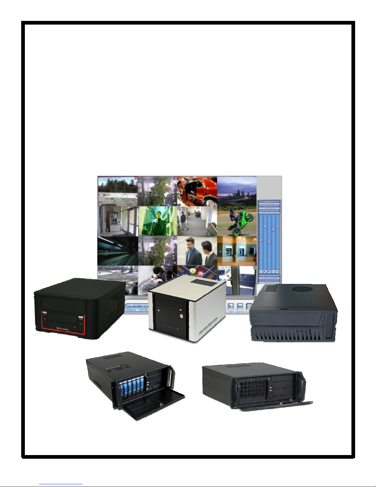
Compatible with:
RP Series DVR (Hybrid)
RP Series Embedded DVR
RP Series NVR
RP Series CVR/ CVR-IP
RP Series i7Max NVR
Page 2

Table of Contents
RP Series—Main Window Layout ……………. ………………………………..…….. 4
Searching and Playback of Recorded Video ...…………………………………….…….. 7
How to Backup Video …………………..………………………..…………………....…….. 8
Playing Back Video ……………………..…………………..…………..……..…..….. 9
Remote Viewing …………………………………………………………...………...…... 10
Video Analytics - Playback ………………………………………………….…...…... 11
Video Analytics - Object Counting Playback …..…………………………………...…... 12
2
Page 3
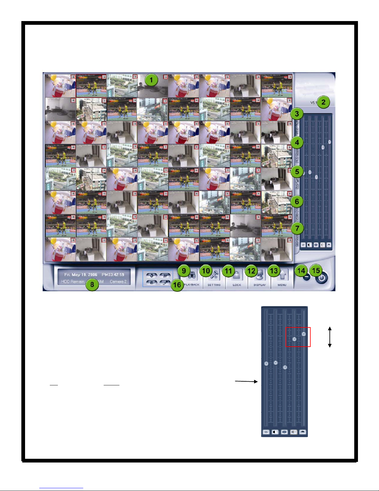
RP Series - Main Window Layout
1. Camera Windows:
Displays live video.
2. Version Information:
Displays the version of the RP Series Software.
3. Video/Audio Adjustments:
Shows the video and audio settings for a
particular camera. Each slide bar configures one camera function. Move the
slider Up
to increase and Down to decrease the settings.
Increase
Decrease
1 - Brightness
2 - Contrast
3 - Hue
4 - Saturation
5 - Audio Volume
1 2 3 4 5
3
Page 4
RP Series - Main Window Layout
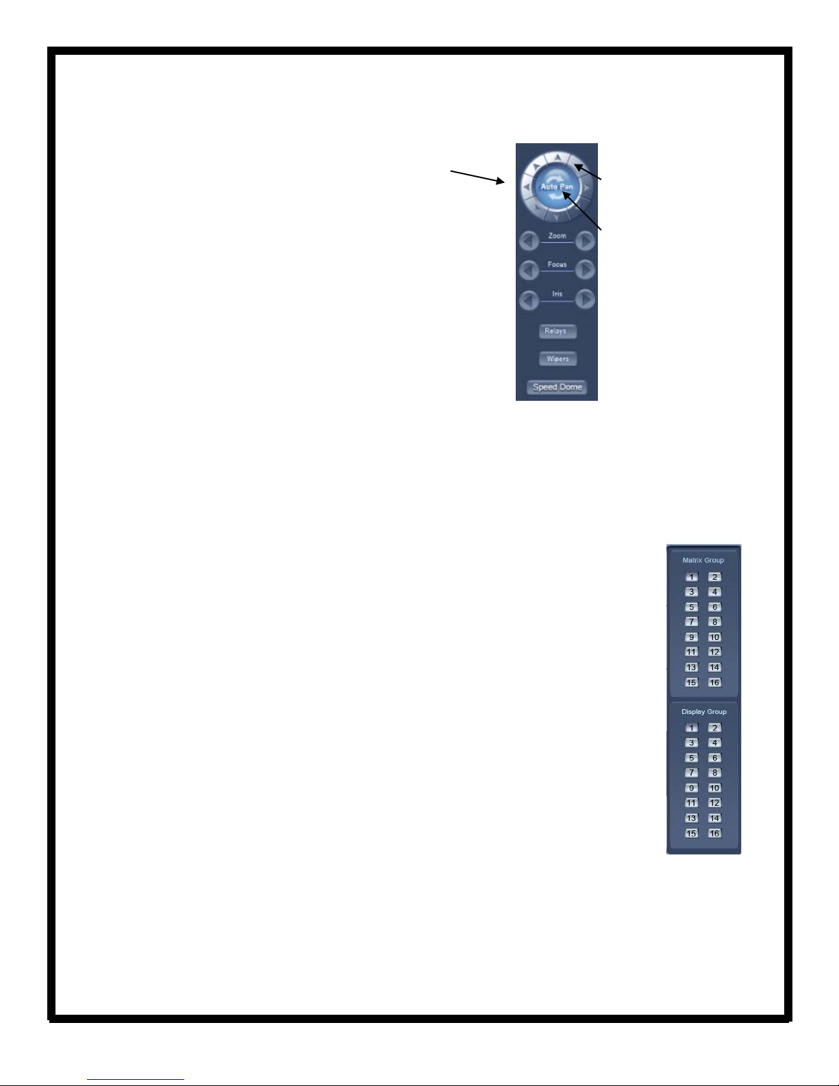
4. PTZ Control:
The PTZ control is used to control connected and
configured PTZ cameras.
Relays (on/off):
Wipers (on/off):
the relay/wiper on and off (For PTZs with a wiper).
Controls the zoom function of the PTZ camera.
Zoom:
Focus:
focus the image.
Overrides the PTZ camera’s auto iris control, allowing the user to brighten/darken the
Iris:
image.
Speed Dome:
Tour.
5. Network Panel:
Relay Toggle (For PTZs using relays).
If using the PTZ cameras corresponding wiper control relay, this toggles
Overrides the auto-focus setting of the PTZ camera, allowing the user to further
Operates the speed dome, including Preset Setup, Preset Call and Preset
The Network Panel displays the current network settings of the RP Series system. This al-
PTZ Directional Controls:
pressing and holding these buttons,
the PTZ camera can be moved left,
right, up and down.
Auto Pan:
supported camera, pressing this
button initiates an automatic tour
of 360
camera.
When using a
0
by the connected PTZ
lows the user to easily view the DVR/NVR’s IP address, which is required for remote viewing and to view any
users who are currently connected.
By
6. Matrix & Display:
Matrix DSP Boards are optional video processors that install in separate
PCI slots in the system. Each board provides 2 Composite Video Out ports and 2 Audio Out
ports. Multiple camera display configurations including camera switching by window are
configurable in setup and can be saved as Groups.
Selecting a particular number from the “Matrix Group” buttons will display the associated
arrangement of cameras (as defined in the group setup) to the video out ports of the matrix
card.
Selecting a particular number from the “Display Group” buttons will display the associated
arrangement of cameras on the main VGA monitor.
4
Page 5

RP Series - Main Window Layout
7. DO Control:
the RP Series DVR. The buttons will not “press” if the I/O device is not active.
8. System Information Panel:
outline) in the video viewing area. You can also change the recording disk manually in the System Information
Panel.
9. Enter Playback Mode:
10. System Setup:
11. System Lock:
unlocking the system using a pre-defined ID and password. The Lock function prompts the user to enter an
unlock password if DVR buttons are attempted to be used. The System Lock button is only available if the “Use
Passwords” option has been set in the Password Setup screen of the System Setup Menu.
12. Display mode:
eras.
The DO Control Panel allows the user to manually open and close any output relays attached to
Displays date and time, amount of free disk space and the camera selected (red
Allows users to playback, search recordings and export video clips.
Allows setup of all operating functions.
The RP Series system can be locked so that no control buttons can be used without first
Selection for number of cameras to be displayed in partitions ranging from 1 to 64 cam-
13. Menu:
log, view system log, motion setup, keyboard shortcuts setup, DVR board
work mode and playback to TV monitor.
This menu displays other system functions including remote chat, open E-Map, write to working
5
Page 6

RP Series - Main Window Layout
14. Minimize button:
15. Exit program:
16. Function Keys:
Auto Switch (camera sequence): When there are more camera s connected than the current
number of camera windows, the additional cameras will be displayed in sequence in the available windows.
Emergency Record Button: Click to record all cameras full-time in “Panic” mode for 30 seconds,
regardless of current recording settings.
Image Capture: Capture a still image from selected (red outline) camera.
Manual record button (on/off): Toggle manual full-time recording selection on/off.
Minimizes the software display onto the start bar.
Allows the software to be shutdown.
6
Page 7

Searching and Playback of Recorded Video
1. From the main software window, click on the Playback button.
2. Under the Date tab, select the date on which the video was recorded. (Highlighted
dates indicate recorded video is stored for those specific days).
3. Under the Cameras tab, select the camera number(s) that has recorded the video.
4. The files tab will show all of the recorded files from connected cameras.
4. Stored video will show in the
highlighted timeline, represented as
darkened areas.
To play a section of video, double click
on any of the darkened areas (video
clip). The video will then play in the
screen above.
7
Page 8

How to Backup Video
1. In the software, click on the Playback
2. From the Backup
Ensure you are choosing the correct timings by searching for the video
content first
3. Select the location where the
video will be saved, the start and
end time of the recording and
what cameras the video will be
chosen from.
Click Check to make
sure the information is
correct, then Backup
save the video content
to the selected area.
(refer to p.9 for directions on how to search for recorded video).
button, select Backup by time from the drop down menu.
to
button.
8
4. The backup procedure will
create a folder that contains the
video files as well as the video
player application that is used to
view the content.
Page 9

Playing Back Video (Codecs, etc)
*In order to playback a section of video, backup of the desired video is first required.
Please refer to the “How to Backup Video” article (page 10).
1.
Open the Player Application (located in the
folder where the backed up video was saved).
The player will list the camera folders
on the left hand side.
2. Open the folder for the corresponding
camera then double click the video file
to play the content.
Display Mode:
Play Speed:
Graphic:
Exit:
Exits the player.
Choose from one screen or four partitions.
Choose from fast, normal or slow.
Takes a snapshot of the video and saves it.
9
Page 10

Remote Viewing
To be able to remotely access the RP Series software, the user must first create an exception in the network’s
firewall (also known as Port Forwarding
1. Log into the router that the system is directly connected to and forward ports 80, 5100 and 5101 to the local IP
address of the system.
2. If there is a modem with an embedded firewall connected to the router, the ports will also have to be opened
in the modem and forwarded to the router’s IP address or simply disable the firewall in the ISP provided modem.
Once these steps are complete, remote viewing of the system is now enabled.
*Contact your ISP to find out what your current public IP address is, or go to an IP Identifying page such as
www.whatismyip.com.
From a remote location there are 2 methods that can be used to log into the system, either use Internet Explorer
or use the RP Series Client Software.
1. In Internet Explorer, type the public IP address into the address bar. This will bring up the RP Series login
page. The default username is admin
NOTE: To use Internet Explorer to view the camera video, Active X controls must be enabled
- In Internet Explorer, click on Tools
Level button. Scroll down the list of plugins and set ALL Active X controls to Enable or Prompt. Ensure none of
them are on Disabled.
1. Install the RP Client Software (called NVR Client) onto a Windows based system that will be used to log
into the system. After the software has been installed, run the application.
2. Click on Settings
address, username and password, then click OK
The system will now be listed on the right hand side of the NVR Client Application. Click the connect button to
connect to the system.
near the bottom then click the Add button in the settings window. Input the system’s IP
).
with no password.
, then Internet Options. Click on the Security tab then click the Custom
.
10
Page 11

Video Analytics - Playback
To playback recorded video and images captured from the Video Analytic features :
1. Right click on the camera that has been set up with Facial
Detection and click Video Intelligent Analysis then select Video
Analysis Playback.
2. Select the camera in the drop down list, the alarm event (facial
detection, motion detection, etc…) and the date/time. Click Search
to display the results.
The events and images captured will appear in the left side of the window.
Double click on one of the images to view the corresponding video on the
right hand side.
Click Exit to return to the main screen.
Missing Object Detection Unattended Object Detection
Facial Detection Intrusion Detection
Page 12

Video Analytics - Object Counting Playback
To access the information gathered from the Object Counting feature:
1. Right click on the camera that has been set up with Object
Counting and click Video Intelligent Analysis then select Object
Counting Analysis.
2. Select the camera that has been set up with Object Counting, the start and end date and the count style (by
month, week, day or hour). Click the Count button to display the results.
Click Exit to return to the main screen.
12
 Loading...