


Sentry
AC Power Distribution Unit
- PTPD-V0, PTPD-H0
- PTPD-VE, PTPD-HE
Installation and Operations Manual

Instructions
This symbol is intended to alert the user to the presence of important operating and maintenance (servicing)
instructions in the literature accompanying the appliance.
Dangerous Voltage
This symbol is intended to alert the user to the presence of un-insulated dangerous voltage within the product’s
enclosure that may be of sufficient magnitude to constitute a risk of electric shock to persons.
Protective Grounding Terminal
This symbol indicates a terminal that must be connected to earth ground prior to making any other connections to
the equipment.
Life-Support Policy
As a general policy, Server Technology does not recommend the use of any of its products in the following situations:
• life-support applications where failure or malfunction of the Server Technology product can be reasonably expected
to cause failure of the life-support device or to significantly affect its safety or effectiveness.
• direct patient care.
Server Technology will not knowingly sell its products for use in such applications unless it receives in writing assurances
satisfactory to Server Technology that:
• the risks of injury or damage have been minimized,
• the customer assumes all such risks, and
• the liability of Server Technology is adequately protected under the circumstances.
The term life-support device includes but is not limited to neonatal oxygen analyzers, nerve stimulators (whether used for
anesthesia, pain relief or other purposes), auto-transfusion devices, blood pumps, defibrillators, arrhythmia detectors and
alarms, pacemakers, hemodialysis systems, peritoneal dialysis systems, neonatal ventilator incubators, ventilators (for
adults or infants), anesthesia ventilators, infusion pumps, and any other devices designated as “critical” by the U.S. FDA.
Compliance
Units have been safety tested/certified to the following standards: USA and Canada to UL 60950:2000 and CAN/CSA
22.2 No. 60950-00, European Union to EN60950:2000
USA Notification
Warning: Changes or modifications to these units not expressly approved by the party responsible for compliance could
void the user’s authority to operate the equipment under FCC rules.
Note: This equipment has been tested and found to comply with the limits for a Class A digital device, pursuant to Part 15
of the FCC Rules. These limits are designed to provide reasonable protection against harmful interference when the
equipment is operated in a commercial environment. This equipment generates, uses and can radiate radio frequency
energy and, if not installed and used in accordance with the instruction manual, may cause harmful interference to radio
communications. Operation of this equipment is a residential area is likely to cause harmful interference in which case the
user will be required to correct the interference at his own expense.
Canadian Notification
This digital apparatus does not exceed the Class A limits for radio noise emissions from digital apparatus set out in the
Radio Interference Regulations of the Canadian Department of Communications.
Le présent appareil numérique n’émet pas de bruits radioélectriques dépassant les limites applicables aux appareils
numériques de la classe A prescrites dans le Règlement sur le brouillage radioélectrique édicté par le Ministère des
Communications du Canada.
Japanese Notification

Table of Contents
CHAPTER 1: INTRODUCTION 1
Features and Benefits ........................................................................................2
Quick Start Guide..............................................................................................2
CHAPTER 2: INSTALLATION 3
Standard Accessories.........................................................................................4
Additional Required Items ................................................................................4
Equipment Overview.........................................................................................4
Safety Precautions.............................................................................................5
Verify Input Voltage Selection (PTPD-VE18 models only).............................5
Mounting ...........................................................................................................6
Connecting to the Power Source .......................................................................6
Connecting Devices to the PTPD......................................................................7
Connecting to the PTPD (PTPD-x0 models only) ............................................7
CHAPTER 3: OPERATIONS (PTPD-X0 MODELS ONLY) 9
Interface...........................................................................................................10
Displaying the Control Screen ........................................................................10
Using the Control Screen ................................................................................10
CHAPTER 4: APPENDICES 13
Appendix A: Resetting to Factory Defaults ....................................................14
Appendix B: Verifying/Setting the Operational Voltage................................15
Appendix C: Technical Specifications............................................................16
Appendix D: Warranty, Product Registration and Support.............................20


Chapter 1: Introduction
FEATURES AND BENEFITS 2
Power Distribution ...........................................................................................................................2
Load Measurement...........................................................................................................................2
Over-Threshold Notification............................................................................................................2
Technical Support ............................................................................................................................2
QUICK START GUIDE 2

Chapter 1: Introduction
The Server Technology Inc. Sentry family of products provides easy, practical, and secure solutions for
power distribution, power management and load-measurement for remote internetworking equipment
and branch AC circuits.
The Sentry Power Distribution Unit (PTPD) provides simple power distribution with cumulative load
monitoring for environments without a requirement for remote power management.
Features and Benefits
Sentry Power Distribution Units are available in 8-outlet, 16-outlet and 18-outlet configurations for
100-120VAC or 208-240VAC up to 30A. See Standard Models in Appendix C: Technical
Specifications.
Power Distribution
A Sentry Power Distribution Unit distributes a maximum of 30A AC power (dependant on PTPD
model) across a maximum of sixteen attached devices.
Load Measurement
The Sentry Power Distribution Unit’s load measurement feature eliminates guesswork by supplying the
cumulative operating load in amperes. This allows on-site technicians to maximize the equipment
installed and operated on a circuit without worry. Use of the circuit is maximized, while effectively
allowing a 10% to 20% safety margin. Remote users also may access this information at any time from
the Control Screen interface (Remote access not available on PTPD-xE models).
Over-Threshold Notification
Sentry Power Distribution Units features two standard over-threshold alarms; an audible alarm for the
local technician and a contact-closure alarm circuit which allows over-threshold alerts to be sent a third
party device (Not available on PTPD-xE models).
Technical Support
Server Technology understands that there are often questions when installing and/or using a new
product. Free Technical Support is provided from 8:30 AM to 5:00 PM, Monday-Friday, Pacific Time.
See Technical Support in Warranty, Product Registration and Support for more information.
Server Technology, Inc.
1040 Sandhill Drive Tel: 775.284.2000 Web: www.servertech.com
Reno, Nevada 89521 USA Fax: 775.284.2065 Email: support@servertech.com
Quick Start Guide
The following instructions will help you quickly install and configure your Sentry Power Distribution
Unit for use on your network. For detailed information on each step, go to the page number listed to
the right.
1. Review all safety notices............................................................................................................5
2. Verify input voltage selection (PTPD-VE18 models only).......................................................15
3. Mount the Sentry Power Distribution Unit.................................................................................5
4. Connect to the power source ......................................................................................................6
5. Connect the devices to the Sentry Power Distribution Unit .......................................................7
6. Configure the Sentry Power Distribution Unit (PTPD-x0 models only).....................................9
Configure location ............................................................................................................10 •
• Configure overload threshold ...........................................................................................10
7. Connect to the Sentry Power Distribution Unit..........................................................................7
2 • Introduction Sentry Power Tower Power Distribution Unit
Installation and Operations Manual

Chapter 2: Installation
STANDARD ACCESSORIES 4
A
DDITIONAL REQUIRED ITEMS 4
E
QUIPMENT OVERVIEW 4
S
AFETY PRECAUTIONS 5
V
ERIFY INPUT VOLTAGE SELECTION (PTPD-VE18 MODELS ONLY) 5
M
OUNTING 6
Horizontal/Rack PTPD.....................................................................................................................6
Vertical PTPD ..................................................................................................................................6
C
ONNECTING TO THE POWER SOURCE 6
C
ONNECTING DEVICES TO THE PTPD 7
C
ONNECTING TO THE PTPD (PTPD-X0 MODELS ONLY) 7
Chapter 2: Installation
8
8
Before installing your Sentry Power Distribution Unit, refer to the following lists to ensure that you
have all the items shipped with the unit as well as all other items required for proper installation.
Standard Accessories
• Mounting bracket hardware:
Vertical - two mounting brackets, two nut plates and four sets of screws and washers
Horizontal/Rack – two mounting brackets and four screws
• Outlet retention clips, one per outlet (208-240V units only)
• Separate power input cord (208-240V units with < 30A total output capability only)
PTPD-x0 models only
• RJ45 to RJ45 crossover cable
• RJ45 to DB9F serial port adapter (for connection to standard DB9M DTE serial port)
Additional Required Items
• Phillip screwdriver
• Screws, washers and nuts to attach the PTPD to your rack
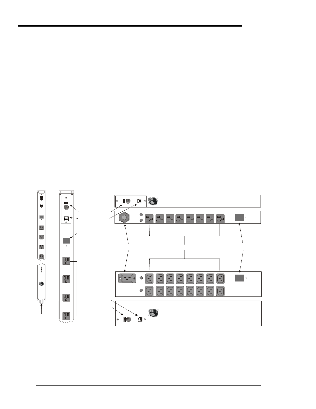
Equipment Overview
A letter/number combination is printed above each PTPD port. The ports are labeled A1 through A4,
B1 through B4, C1 through C4 and D1through D4. The power inlet of the PTPD connects the PTPD to
the electrical power source. See Appendix C: Technical Specifications for more information.
Alarm
Input
Current
88
Sentry
Power
Tow er
Server
Techno logy
www.ser vertech.c om
Output
RS-232
Alarm
Reset
A1
A2
A3
A4
Inc.
Alarm
Output
RS-232
Inp ut
Current
8888
Alarm
Reset
A1
A2
A3
IDC10 Connector
RJ45 Connector
Input Current LED
Ports
t
2
u
m
r
a
l
A
3
p
2
t
-
u
S
R
O
AC Power Inlet
RJ45 Connector
IDC10 Connector
t
u
m
r
p
t
a
l
u
A
O
AC Power Inlet
100-120V Vertical
(Fuses not shown)
A4
Figure 2.1 PTPD Views (PTPD-x0 model types shown)
100-120V Horizontal/Rack 8-port
Sentry Power Tower
Server Technolog y, Inc.
www.servertech.com
B4 B3 B2 B1 A4 A3 A2 A 1
Fuse A
Fuse B
Ports
B4 B3 B2 B1 A4 A3 A2 A1
Fuse A
D4 D3 D2 D1 C4 C3 C2 C1
Fuse B
Sentry Power Tower
Server Technology, Inc.
2
3
2
S
R
www.servertech.com
208-240V Horizontal/Rack 16-port
TM
Input
Current
88
Alarm
Reset
8
Input Current LED
Input
Current
TM
88
Alarm
Reset
8
4 • Installation Sentry Power Tower Power Distribution Unit
Installation and Operations Manual
 Loading...