

Page 1

Sentry
AC Power Distribution Unit
- PTPD-V0, PTPD-H0
- PTPD-VE, PTPD-HE
Installation and Operations Manual
Page 2

Instructions
This symbol is intended to alert the user to the presence of important operating and maintenance (servicing)
instructions in the literature accompanying the appliance.
Dangerous Voltage
This symbol is intended to alert the user to the presence of un-insulated dangerous voltage within the product’s
enclosure that may be of sufficient magnitude to constitute a risk of electric shock to persons.
Protective Grounding Terminal
This symbol indicates a terminal that must be connected to earth ground prior to making any other connections to
the equipment.
Life-Support Policy
As a general policy, Server Technology does not recommend the use of any of its products in the following situations:
• life-support applications where failure or malfunction of the Server Technology product can be reasonably expected
to cause failure of the life-support device or to significantly affect its safety or effectiveness.
• direct patient care.
Server Technology will not knowingly sell its products for use in such applications unless it receives in writing assurances
satisfactory to Server Technology that:
• the risks of injury or damage have been minimized,
• the customer assumes all such risks, and
• the liability of Server Technology is adequately protected under the circumstances.
The term life-support device includes but is not limited to neonatal oxygen analyzers, nerve stimulators (whether used for
anesthesia, pain relief or other purposes), auto-transfusion devices, blood pumps, defibrillators, arrhythmia detectors and
alarms, pacemakers, hemodialysis systems, peritoneal dialysis systems, neonatal ventilator incubators, ventilators (for
adults or infants), anesthesia ventilators, infusion pumps, and any other devices designated as “critical” by the U.S. FDA.
Compliance
Units have been safety tested/certified to the following standards: USA and Canada to UL 60950:2000 and CAN/CSA
22.2 No. 60950-00, European Union to EN60950:2000
USA Notification
Warning: Changes or modifications to these units not expressly approved by the party responsible for compliance could
void the user’s authority to operate the equipment under FCC rules.
Note: This equipment has been tested and found to comply with the limits for a Class A digital device, pursuant to Part 15
of the FCC Rules. These limits are designed to provide reasonable protection against harmful interference when the
equipment is operated in a commercial environment. This equipment generates, uses and can radiate radio frequency
energy and, if not installed and used in accordance with the instruction manual, may cause harmful interference to radio
communications. Operation of this equipment is a residential area is likely to cause harmful interference in which case the
user will be required to correct the interference at his own expense.
Canadian Notification
This digital apparatus does not exceed the Class A limits for radio noise emissions from digital apparatus set out in the
Radio Interference Regulations of the Canadian Department of Communications.
Le présent appareil numérique n’émet pas de bruits radioélectriques dépassant les limites applicables aux appareils
numériques de la classe A prescrites dans le Règlement sur le brouillage radioélectrique édicté par le Ministère des
Communications du Canada.
Japanese Notification
Page 3

Table of Contents
CHAPTER 1: INTRODUCTION 1
Features and Benefits ........................................................................................2
Quick Start Guide..............................................................................................2
CHAPTER 2: INSTALLATION 3
Standard Accessories.........................................................................................4
Additional Required Items ................................................................................4
Equipment Overview.........................................................................................4
Safety Precautions.............................................................................................5
Verify Input Voltage Selection (PTPD-VE18 models only).............................5
Mounting ...........................................................................................................6
Connecting to the Power Source .......................................................................6
Connecting Devices to the PTPD......................................................................7
Connecting to the PTPD (PTPD-x0 models only) ............................................7
CHAPTER 3: OPERATIONS (PTPD-X0 MODELS ONLY) 9
Interface...........................................................................................................10
Displaying the Control Screen ........................................................................10
Using the Control Screen ................................................................................10
CHAPTER 4: APPENDICES 13
Appendix A: Resetting to Factory Defaults ....................................................14
Appendix B: Verifying/Setting the Operational Voltage................................15
Appendix C: Technical Specifications............................................................16
Appendix D: Warranty, Product Registration and Support.............................20
Page 4

Page 5

Chapter 1: Introduction
FEATURES AND BENEFITS 2
Power Distribution ...........................................................................................................................2
Load Measurement...........................................................................................................................2
Over-Threshold Notification............................................................................................................2
Technical Support ............................................................................................................................2
QUICK START GUIDE 2
Page 6

Chapter 1: Introduction
The Server Technology Inc. Sentry family of products provides easy, practical, and secure solutions for
power distribution, power management and load-measurement for remote internetworking equipment
and branch AC circuits.
The Sentry Power Distribution Unit (PTPD) provides simple power distribution with cumulative load
monitoring for environments without a requirement for remote power management.
Features and Benefits
Sentry Power Distribution Units are available in 8-outlet, 16-outlet and 18-outlet configurations for
100-120VAC or 208-240VAC up to 30A. See Standard Models in Appendix C: Technical
Specifications.
Power Distribution
A Sentry Power Distribution Unit distributes a maximum of 30A AC power (dependant on PTPD
model) across a maximum of sixteen attached devices.
Load Measurement
The Sentry Power Distribution Unit’s load measurement feature eliminates guesswork by supplying the
cumulative operating load in amperes. This allows on-site technicians to maximize the equipment
installed and operated on a circuit without worry. Use of the circuit is maximized, while effectively
allowing a 10% to 20% safety margin. Remote users also may access this information at any time from
the Control Screen interface (Remote access not available on PTPD-xE models).
Over-Threshold Notification
Sentry Power Distribution Units features two standard over-threshold alarms; an audible alarm for the
local technician and a contact-closure alarm circuit which allows over-threshold alerts to be sent a third
party device (Not available on PTPD-xE models).
Technical Support
Server Technology understands that there are often questions when installing and/or using a new
product. Free Technical Support is provided from 8:30 AM to 5:00 PM, Monday-Friday, Pacific Time.
See Technical Support in Warranty, Product Registration and Support for more information.
Server Technology, Inc.
1040 Sandhill Drive Tel: 775.284.2000 Web: www.servertech.com
Reno, Nevada 89521 USA Fax: 775.284.2065 Email: support@servertech.com
Quick Start Guide
The following instructions will help you quickly install and configure your Sentry Power Distribution
Unit for use on your network. For detailed information on each step, go to the page number listed to
the right.
1. Review all safety notices............................................................................................................5
2. Verify input voltage selection (PTPD-VE18 models only).......................................................15
3. Mount the Sentry Power Distribution Unit.................................................................................5
4. Connect to the power source ......................................................................................................6
5. Connect the devices to the Sentry Power Distribution Unit .......................................................7
6. Configure the Sentry Power Distribution Unit (PTPD-x0 models only).....................................9
Configure location ............................................................................................................10 •
• Configure overload threshold ...........................................................................................10
7. Connect to the Sentry Power Distribution Unit..........................................................................7
2 • Introduction Sentry Power Tower Power Distribution Unit
Installation and Operations Manual
Page 7

Chapter 2: Installation
STANDARD ACCESSORIES 4
A
DDITIONAL REQUIRED ITEMS 4
E
QUIPMENT OVERVIEW 4
S
AFETY PRECAUTIONS 5
V
ERIFY INPUT VOLTAGE SELECTION (PTPD-VE18 MODELS ONLY) 5
M
OUNTING 6
Horizontal/Rack PTPD.....................................................................................................................6
Vertical PTPD ..................................................................................................................................6
C
ONNECTING TO THE POWER SOURCE 6
C
ONNECTING DEVICES TO THE PTPD 7
C
ONNECTING TO THE PTPD (PTPD-X0 MODELS ONLY) 7
Page 8
Chapter 2: Installation
8
8
Before installing your Sentry Power Distribution Unit, refer to the following lists to ensure that you
have all the items shipped with the unit as well as all other items required for proper installation.
Standard Accessories
• Mounting bracket hardware:
Vertical - two mounting brackets, two nut plates and four sets of screws and washers
Horizontal/Rack – two mounting brackets and four screws
• Outlet retention clips, one per outlet (208-240V units only)
• Separate power input cord (208-240V units with < 30A total output capability only)
PTPD-x0 models only
• RJ45 to RJ45 crossover cable
• RJ45 to DB9F serial port adapter (for connection to standard DB9M DTE serial port)
Additional Required Items
• Phillip screwdriver
• Screws, washers and nuts to attach the PTPD to your rack
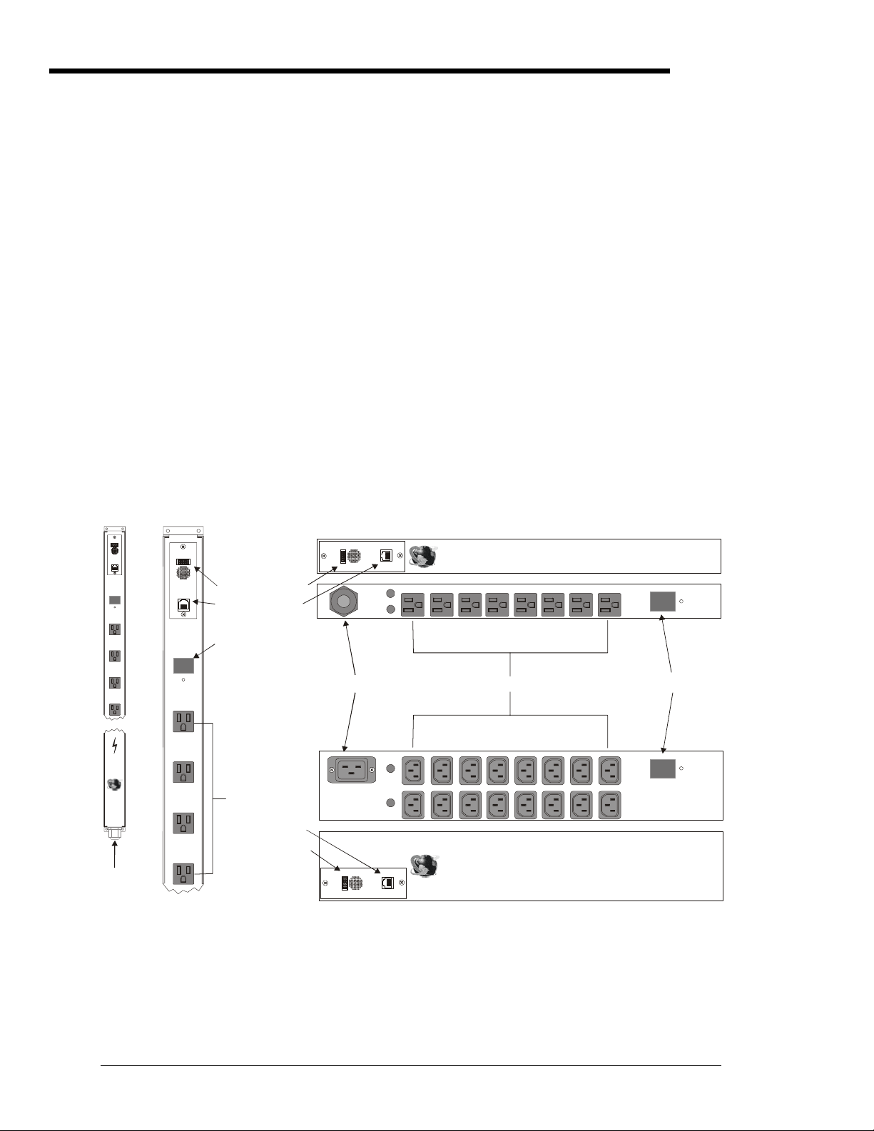
Equipment Overview
A letter/number combination is printed above each PTPD port. The ports are labeled A1 through A4,
B1 through B4, C1 through C4 and D1through D4. The power inlet of the PTPD connects the PTPD to
the electrical power source. See Appendix C: Technical Specifications for more information.
Alarm
Input
Current
88
Sentry
Power
Tow er
Server
Techno logy
www.ser vertech.c om
Output
RS-232
Alarm
Reset
A1
A2
A3
A4
Inc.
Alarm
Output
RS-232
Inp ut
Current
8888
Alarm
Reset
A1
A2
A3
IDC10 Connector
RJ45 Connector
Input Current LED
Ports
t
2
u
m
r
a
l
A
3
p
2
t
-
u
S
R
O
AC Power Inlet
RJ45 Connector
IDC10 Connector
t
u
m
r
p
t
a
l
u
A
O
AC Power Inlet
100-120V Vertical
(Fuses not shown)
A4
Figure 2.1 PTPD Views (PTPD-x0 model types shown)
100-120V Horizontal/Rack 8-port
Sentry Power Tower
Server Technolog y, Inc.
www.servertech.com
B4 B3 B2 B1 A4 A3 A2 A 1
Fuse A
Fuse B
Ports
B4 B3 B2 B1 A4 A3 A2 A1
Fuse A
D4 D3 D2 D1 C4 C3 C2 C1
Fuse B
Sentry Power Tower
Server Technology, Inc.
2
3
2
S
R
www.servertech.com
208-240V Horizontal/Rack 16-port
TM
Input
Current
88
Alarm
Reset
8
Input Current LED
Input
Current
TM
88
Alarm
Reset
8
4 • Installation Sentry Power Tower Power Distribution Unit
Installation and Operations Manual
Page 9

Safety Precautions
This section contains important safety and regulatory information that should be reviewed before
installing and using the Sentry Sentry Power Distribution Unit. For input and output current ratings,
see Ratings in Appendix C: Technical Specifications.
Only for installation and use in a
Service Access Location in accordance
with the following installation and use
instructions.
This equipment is designed to be
installed on a dedicated circuit.
Dedicated circuit must have circuit
breaker or fuse protection. Sentry
Power Distribution Units have been
designed without a master circuit
breaker or fuse to avoid becoming a
single point of failure. It is the
customer's responsibility to provide
adequate protection for the dedicated
power circuit. Protection of capacity
equal to current rating of equipment,
and must meet all applicable codes and
regulations. Circuit breaker or fuse for
installation in North America must have
10,000A interrupt capacity.
The plug on the power supply cord
shall be installed near the equipment
and shall be easily accessible.
Installation Orientation: PTxx-Vxxx-x
units are design to be installed in
vertical orientation.
Always disconnect the power supply
cord before opening to avoid electrical
shock.
WARNING! High leakage current!
Earth connection is essential before
connecting supply!
Warning: 208-240/230V models only:
Outlets are not fused. Outlet circuit
protection is provided by the building
installation, which shall not exceed 30A
branch circuit protection
For PTPD-VE18 models, verify input
voltage selection PRIOR to connection.
See Appendix B: for more information.
Destiné à l'installation et l'utilisation
dans le cadre de Service Access
Location selon les instructions
d'installation et d'utilisation.
Cet équipement est conçu à être
installé sur un circuit spécialisé.
Le circuit spécialisé doit avoir un
disjoncteur ou une protection de
fusible. Des Sentry Power Distribution
Units ont été conçus sans disjoncteur
général ni fusible pour éviter que cela
devient un seul endroit de panne.
C’est la responsabilité du client de
fournir une protection adéquate pour le
circuit-alimentation spécialisé.
Protection de capacité équivalant à la
puissance de l'équipement, et
respectant tous les codes et normes
applicables. Les disjoncteurs ou
fusibles destinés à l'installation en
Amérique du Nord doivent avoir une
capacité d'interruption de 10 000 A.
La prise sur le cordon d’alimentation
sera installée près de l’équipement et
sera facilement disponible.
Installation Orientation : Les unités
PTxx-Vxxx-x sont conçues pour être
installées dans une orientation
verticale.
Toujours déconnecter le cordon
d’alimentation avant d’ouvrir pour
éviter un choque électrique.
ATTENTION ! Haut fuite très
possible ! Une connection de masse
est essentielle avant de connecter
l’alimentation !
Attention: les modèles 208-240/230V
seulement : Les prises n’ont pas de
fusible incorporé. Une protection de la
prise du circuit est fournie par
l’installation du bâtiment, qui ne devrait
pas dépasser 30A protection d’une
branche de circuit.
Pour PTPD-VE18 modèles, vérifier de
la sélection de tension de données
AVANT la connexion. Voir le B
d'Appendice: pour plus amples
renseignements.
Nur für Installation und Gebrauch an
Anschlusszugriffspunkten gemäß der
folgenden Installations- und
Gebrauchsanweisungen.
Diese Ausrüstung ist zur Installation in
einem festen Stromkreis vorgesehen.
Der feste Stromkreis muss mit einem
Schutzschalter oder einem
Sicherungsschutz versehen sein.
Ein Sentry Power Distribution Units
verfügt über keinen
Hauptschutzschalter bzw. über keine
Sicherung, damit kein einzelner
Fehlerpunkt entstehen kann. Der
Kapazitätsschutz entspricht der
aktuellen Stromstärke der Geräte und
muss alle relevanten Codes und
Bestimmungen erfüllen. Für Installation
in Nordamerika müssen Ausschalter
bzw. Sicherung über 10.000 A
Unterbrechungskapazität verfügen.
Der Stecker des Netzkabels muss in
der Nähe der Ausrüstung installiert
werden und leicht zugänglich sein.
Installationsausrichtung: PTxx-Vxxx-x
Einheiten sind zur vertikalen Installation
vorgesehen.
Ziehen Sie vor dem Öffnen immer das
Netzkabel heraus, um die Gefahr eines
elektrischen Schlags zu vermeiden.
ACHTUNG! Hoher Verluststrom! Ein
Erdungsanschluss ist vor dem
Einschalten der Stromzufuhr
erforderlich!
Achtung: Nur für 208-240/230VModelle: Die Anschlussstellen sind
nicht gesichert. Der
Ausgangsstromkreisschutz erfolgt
durch die elektrische
Gebäudeinstallation, die einen
Abzweigschutz von 30A nicht
übersteigen darf.
Für PTPD-VE18 entwerfen Sie,
Überprüfen Sie Eingabespannung
Auswahl VOR Anschluß. Siehe
Anhang B: für mehr Informationen.
Verify Input Voltage Selection (PTPD-VE18 models only)
Verify input voltage selection PRIOR to connection. See Appendix B: on page 15 for instructions.
Vérifier de la sélection de tension de données AVANT la connexion. Voir le B d'Appendice: à la page 15 pour les instructions.
Uberprüfen Sie Eingabespannung Auswahl VOR Anschluß. Siehe Anhang B: Auf Seite 15 für Anweisungen.
Sentry Power Tower Power Distribution Unit Installation • 5
Installation and Operations Manual
Page 10

Mounting
Horizontal/Rack PTPD
1. Select the appropriate bracket mounting points for proper mounting depth within the rack.
2. Attach one bracket to these mounting points with two screws.
3. Repeat with the other mounting bracket on the opposite side of the enclosure.
4. Install the enclosure into your rack, using the slots in each bracket. The slots allow about ¼ inch
of horizontal adaptability to align with the mounting holes of your rack.
NOTE: A mounting bracket kit for 23” wide rack or cabinets is available. Contact your Server Technology Sales
Representative for more information.
Vertical PTPD
1. Attach one of the removable flanges to the mount points on the top rear of the enclosure using M4
screws.
2. Repeat with the other flange for the bottom mount points on the enclosure.
3. Attach one mounting bracket to the top flange with one set of screws and washers through each of
the slots in the bracket into the nut plate, as shown in Figure 2.2 (brackets may differ from the
illustration). The slots allow about 1½ inches of vertical adaptability.
4. Repeat with the other mounting bracket on the bottom flange.
5. Attach the top and bottom brackets to your rack.
NOTE: Contact your Server Technology Sales Representative for information regarding custom bracket design and
fabrication services if you are unable to find a suitable manner for utilizing the included mounting brackets.
Connecting to the Power Source
On all 100-120V units and 208-240V units with a total output rating of 30A, the input power cord is
attached to the base of the PTPD unit. On 208-240V units with a total output rating <30, you must first
attach the power cord to the PTPD unit before connecting the PTPD to the power source.
To attach a 230V power cord to the 230V PTPD unit:
1. Plug the female end of the power cord firmly into its connector at the base of the PTPD.
2. Use a screwdriver to tighten the two screws on the retention bracket.
To connect the PTPD to the power source:
Plug the male end of the PTPD power cord into the AC power source.
On power up, PTPD-x0 models perform a self-test and display the results on the terminal screen:
• The Input Current LED displays ‘On’, then switches to the cumulative input load.
• The audible alarm and contact-closure output relay are triggered for one second.
Power Tower PDU Version 1.0b
Booting...
Display Detected, Status OK, Configured.
Power Supply Detected, Status OK, Configured, ADC Enabled.
EEPROM Detected, Configuration Loaded.
Boot Complete.
Figure 2.2 Example of power up self-test results.
6 • Installation Sentry Power Tower Power Distribution Unit
Installation and Operations Manual
Page 11

Connecting Devices to the PTPD
To avoid the possibility of noise due to arcing:
Keep the device’s on/off switch in the off position until after it is plugged into the PTPD port.
On 115V units, connect devices to the PTPD ports.
On 230V units, install a retention clip on each port. Pull the open prongs out slightly and insert them
into holes on the sides of the PTPD adjacent to the port. Then insert the device’s power cord and gently
snap the retention clip over the cord.
NOTE:
1. Server Technology recommends even distribution of attached devices across the all available outlets to avoid
exceeding the outlet, quad or octet ratings limitations. See Ratings in Appendix B: for more information.
2. The outlet retention clips on the 230V PTPD are designed for use with Server Technology’s IEC 60320/C13 to IEC
60320/C14 cable (CAB-1302). The retention clip may not properly fit 3
Always disconnect the power supply cord before opening to avoid electrical shock.
Afin d’éviter les chocs électriques, débranchez le cable électrique avant d’ouvrir.
Immer Netzleitung auskuppeln vor den Aufmachen um elektrischen Schlag zu vermeiden.
rd
party cables.
Connecting to the PTPD (PTPD-x0 models only)
The Sentry Power Distribution Unit is equipped with a single RJ45 RS-232 serial port for attachment to
a PC or networked terminal server using the supplied RJ45 to RJ45 crossover cable and RJ45 to DB9F
serial port adapter as required. Additionally, the PTPD is equipped with a single IDC10 alarm port for
connection to contact-closure overload alarm circuits. See Chapter 4: Appendices for more
information these ports.
Sentry Power Tower Power Distribution Unit Installation • 7
Installation and Operations Manual
Page 12

Page 13

Chapter 3: Operations (PTPD-x0 models only)
INTERFACE 10
D
ISPLAYING THE CONTROL SCREEN 10
To display or refresh the Control Screen: ............................................................................10
USING THE CONTROL SCREEN 10
Location field .................................................................................................................................10
To specify a location: ...........................................................................................................10
Input Current field..........................................................................................................................10
Threshold field ...............................................................................................................................10
To adjust the overload threshold:.........................................................................................10
Alarm Status field...........................................................................................................................11
Clearing an Over-Threshold Alarm......................................................................................11
To clear an alarm from the Control Screen: ........................................................................11
To clear an alarm using the reset button:.............................................................................11
Ending a Session ............................................................................................................................11
Page 14

Chapter 3: Operations (PTPD-x0 models only)
Interface
The Sentry Power Distribution Unit has one interface: the Control Screen. This screen displays all data
from the Power Distribution Unit.
Displaying the Control Screen
Displaying the Control Screen of a PTPD requires the use of a terminal or terminal emulation software.
The terminal or emulation software must be configured to support ANSI or VT100, a supported data
rate (300, 1200, 2400, 4800, 9600, 19200, or 38400 BPS)- 8 data bits-no parity-one stop bit and Device
Ready output signal (DTR or DSR).
To display or refresh the Control Screen:
Press Enter.
Using the Control Screen
The Control Screen displays all status information for the Sentry Power Distribution Unit. Figure 3.1
shows an example of the Control Screen.
Power Tower PDU Version 1.0b
Location:
Input Current: 0.00 Amps
Alarm Status: No Alarm
Threshold: 30 Amps
Press ‘L’ to edit Location
Press ‘T’ to adjust Threshold
Press ‘Enter’ to refresh
Figure 3.1 Example Control Screen
Control Screen Key Commands
Key Action
L Pressing L allows editing of the Location field.
T Pressing T allows editing of the overload threshold.
Enter Displays or refreshes the Control Screen.
The following sections describe each Control Screen field.
Location field
The editable Location field may contain a descriptive location for the PTPD.
To specify a location:
Type L. If you are changing an existing name, press the Backspace key to erase characters. Enter a 130 character string and press Enter.
Input Current field
The display-only Input Current field indicates the current cumulative input load for the PTPD, in
quarter-ampere granularity. Additionally, the digital LED above the ports on the PTPD indicates the
total input load in half-ampere granularity to 10 amperes and whole ampere granularity above 10
amperes.
Threshold field
The editable Threshold field indicates the PTPD ’s current overload threshold setting. If the Input
Current exceeds the Threshold by 1/8 ampere the PTPD will trigger the audible alarm and the contactclosure alarm output.
To adjust the overload threshold:
Type t. Use the + and – key to increase or decrease the threshold value in Amperes. The threshold
may be set from 1-31. Press Enter.
10 • Operations (PTPD-x0 models only) Sentry Power Tower Power Distribution Unit
Installation and Operations Manual
Page 15

Alarm Status field
The display-only Control Status field indicates the PTPD ’s current alarm state.
Alarm Status Field Values
Display Description
No Alarm Current PTPD load is under overload threshold setting.
ALARM -> Over Threshold Current PTPD load exceeds overload threshold setting.
ALARM (Cleared) -> Over Threshold Alarm reset - Current PTPD load exceeds overload threshold setting.
Power Tower PDU Version 1.0b
Location:
Input Current: 20.25 Amps
Alarm Status: ALARM -> Over Threshold
Threshold: 20 Amps
Press ‘C’ to clear Alarm
Press ‘L’ to edit Location
Press ‘T’ to adjust Threshold
Press ‘Enter’ to refresh
Figure 3.2 Example Control Screen in an over-threshold condition
Clearing an Over-Threshold Alarm
The over-threshold alarm may be cleared from the Control Screen or by pressing the Alarm Reset button.
Clearing the alarm resets both the audible alarm and the contact-closure alarm output.
NOTE: The alarm is automatically cleared if the Input Current returns to 1/8 ampere below the overload threshold.
To clear an alarm from the Control Screen:
Type c.
To clear an alarm using the reset button:
On the front of the PTPD, locate the recessed reset button directly below the Input Current LED. You
will need a non-conductive, non-metallic tool that fits inside the recess.
Insert the tool, then depress and hold the reset button until the audible alarm is silenced.
NOTE: The reset button should be released immediately after the audible alarm is silenced. Failure to release within 7
seconds will result in resetting the PTPD to factory defaults. See Appendix A: Resetting to Factory Defaults for more
information.
Power Tower PDU Version 1.0b
Location:
Input Current: 20.25 Amps
Alarm Status: ALARM (Cleared) -> Over Threshold
Threshold: 20 Amps
Press ‘L’ to edit Location
Press ‘T’ to adjust Threshold
Press ‘Enter’ to refresh
Figure 3.3 Example Control Screen with a cleared over-threshold condition.
Ending a Session
Sessions are ended automatically after each refresh of the Control Screen.
Sentry Power Tower Power Distribution Unit Operations (PTPD-x0 models only) • 11
Installation and Operations Manual
Page 16

Page 17

Chapter 4: Appendices
APPENDIX A: RESETTING TO FACTORY DEFAULTS 14
To reset the PTPD to factory defaults using the reset button: ........................................................14
APPENDIX B: VERIFYING/SETTING THE OPERATIONAL VOLTAGE 15
A
PPENDIX C: TECHNICAL SPECIFICATIONS 16
Standard Models.............................................................................................................................16
Ratings............................................................................................................................................17
Fuses...............................................................................................................................................17
Data Connection (PTPD-x0 models only)......................................................................................18
RJ45 to DB9F serial port adapter...................................................................................................18
IDC10 alarm port ...........................................................................................................................19
APPENDIX D: WARRANTY, PRODUCT REGISTRATION AND SUPPORT 20
Warranty and Limitation of Liability .............................................................................................20
Product Registration.......................................................................................................................20
Technical Support ..........................................................................................................................20
Return Merchandise Authorization ................................................................................................20
Page 18

Chapter 4: Appendices
Appendix A: Resetting to Factory Defaults
You may reset the non-volatile RAM that stores all configurable Sentry Power Distribution Unit
options. This clears all editable fields on the Control Screen.
You may reset the Sentry Power Distribution Unit to factory defaults by pressing the reset button.
To reset the PTPD to factory defaults using the reset button:
On the front of the PTPD, locate the recessed reset button directly below the Input Current LED. You
will need a non-conductive, non-metallic tool that fits inside the recess.
Insert the tool in the recess, then depress and hold the reset button for at least 8 seconds. A reset is
indicated by three side-by-side pairs of horizontal lines in the top, middle and bottom of the display. At
this point, you may release the reset button. The PTPD will perform a power up self-test and then
return to displaying the cumulative input load on the Input Current LED.
14 • Appendices Sentry Power Tower Power Distribution Unit
Resetting to Factory Defaults Installation and Operations Manual
Page 19

Appendix B: Verifying/Setting the Operational Voltage
Vérification/réglage de la tension de service
Überprüfen/Einstellen der Betriebsspannung
PTPD-VE18 models are equipped with an internal input voltage selector switch, for operation in either
a 100-120V or a 208-240V environment.
THIS OPERATION SHOULD ONLY BE PERFORMED BY A QUALIFIED TECHNICIAN.
The customer is responsible for proper identification of required input voltage and configuration of the Sentry
Power Distribution Unit.
The customer assumes responsibility and liability for possible damage to the Sentry Power Distribution Unit, 3
party equipment and/or injury to personnel due to improper configuration.
CETTE OPERATION NE DOIT ETRE FAIRE QUE PAR UN TECHNICIEN QUALIFIE.
Il incombe au client de déterminer correctement la tension d’entrée et la configuration du Sentry Power
Distribution Unit.
Le client prend la responsabilité si la Tour Electrique est endommagée, autre équipement/ou blessure de
personnels à cause d’une configuration incorrecte.
DIESE ARBEITEN SOLLTEN NUR VON EINEM QUALIFIZIERTEN TECHNIKER DURCHGEFÜHRT
WERDEN.
Der Kunde ist für die Ermittlung der erforderlichen Eingangsspannung und die Konfiguration des Sentry Power
Distribution Unit verantwortlich.
Der Kunde die Verantwortung und Haftung für eine etwaige Beschädigung des Sentry Power Distribution Unit,
der Ausrüstung von Fremdfirmen und/oder Verletzungen von Mitarbeitern durch Falsche Konfiguration.
Tools needed:
1. Philips screwdriver
Outils nécessaires:
1. Tournevis cruciforme
Benötigtes Werkzeug Teile:
1. Kreuzschlitzschraubenzieher
rd
230V
Voltage selector switch
Sélecteur de tension
Spannungswahlschalter
Procedure:
1. Unplug Sentry Power
Distribution Unit.
2. Open the rear access plate.
2.1. Remove both screws from
access plate on the back of
the Sentry Power
Distribution Unit.
2.2. Remove the access plate.
3. Verify the proper setting on the
voltage selector switch.
Correct as necessary.
115V – for 100-120V
230V – for 208-240V
4. Replace rear access plate and
secure with original screws.
NOTE:
Changing the voltage setting of the Sentry Power Distribution Unit may require changing of the input power cord. For
information on changing the input power cord, go to www.servertech.com.
Le changement du réglage de tension du Sentry Power Distribution Unit peur exiger le changement du cordon
d’alimentation. Pour toute information concernant le changement du cordon, consulter le site www.servertech.com.
Bei einer Änderung der Spannungseinstellung des Sentry Power Distribution Unit muss unter Umständen das Netzkabel
ausgetauscht werden. Informationen über den Austausch des Netzkabels finden Sie unter www.servertech.com.
Procédure:
1. Débrancher la Sentry Power
Distribution Unit.
2. Ouvrir la plaque d’accès de
dernière.
2.1. Enlever les deux vis de la
plaque d’accès dernière la
Power Twoer.
2.2. Enlever la plaque d’accès.
3. Vérifier que le sélecteur de
tension est correctement
positionné. Changer le réglage
selon le besoin.
115V – pour 100 -120V
230V – pour 208-240V
4. Remettre la plaque de dernière
et fermer bien avec les vis
original.
Vorgangsweise:
1. Ziehen Sie den Stecker des
Sentry Power Distribution
Unit heraus.
2. Öffnen Sie die hintere
Abdeckung.
2.1. Entfernen Sie beide
Schrauben aus der
hinteren Abdeckung des
Sentry Power Distribution
Unit.
2.2. Nehmen Sie die
Abdeckung ab.
3. Vergewissern Sie sich, dass
der Spannungswahlschalter
richtig eingestellt ist. Ändern
Sie die Einstellung bei
Bedarf.
115V - für 100 - 120 V
230V - für 208 - 240 V
4. Bringen Sie die hintere
Abdeckung wieder an, und
befestigen Sie sie mit den
Originalschrauben.
Sentry Power Tower Power Distribution Unit Appendices • 15
Installation and Operations Manual Verifying/Setting the Operational Voltage
Page 20

Appendix C: Technical Specifications
Standard Models
Vertical Installation
Model Voltage Inlet Cordset (10’) Outlets
PTPD-V008-1-01 100-120V, 50/60Hz Hardwired NEMA 5-20P, 20A/125V straight 8 NEMA 5-20R
PTPD-V008-1-03 100-120V, 50/60Hz Hardwired NEMA 5-15P, 15A/125V straight 8 NEMA 5-20R
PTPD-V008-1-04 100-120V, 50/60Hz Hardwired NEMA L5-20P, 20A/125V locking 8 NEMA 5-20R
PTPD-V008-1-05 100-120V, 50/60Hz Hardwired NEMA L5-30P, 30A/125V locking 8 NEMA 5-20R
PTPD-V008-2-02 208-240V, 50/60Hz IEC 60320/C20 *
PTPD-V008-2-06 208-240V, 50/60Hz Hardwired NEMA L6-30P, 30A/230V locking 8 IEC 60320/C13
PTPD-V016-1-01 100-120V, 50/60Hz Hardwired NEMA 5-20P, 20A/125V straight 16 NEMA 5-20R
PTPD-V016-1-03 100-120V, 50/60Hz Hardwired NEMA 5-15P, 15A/125V straight 16 NEMA 5-20R
PTPD-V016-1-04 100-120V, 50/60Hz Hardwired NEMA L5-20P, 20A/125V locking 16 NEMA 5-20R
PTPD-V016-1-05 100-120V, 50/60Hz Hardwired NEMA L5-30P, 30A/125V locking 16 NEMA 5-20R
PTPD-V016-2-02 208-240V, 50/60Hz IEC 60320/C20 * 16 IEC 60320/C13
PTPD-V016-2-06 208-240V, 50/60Hz Hardwired NEMA L6-30P, 30A/230V locking 16 IEC 60320/C13
PTPD-VE16-1-01 100-120V, 50/60Hz Hardwired NEMA 5-20P, 20A/125V straight 16 NEMA 5-20R
PTPD-VE16-1-03 100-120V, 50/60Hz Hardwired NEMA 5-15P, 15A/125V straight 16 NEMA 5-20R
PTPD-VE16-1-04 100-120V, 50/60Hz Hardwired NEMA L5-20P, 20A/125V locking 16 NEMA 5-20R
PTPD-VE16-1-05 100-120V, 50/60Hz Hardwired NEMA L5-30P, 30A/125V locking 16 NEMA 5-20R
PTPD-VE18-0-01 100-240V, 50/60Hz Hardwired NEMA 5-20P, 20A/125V straight 18 IEC 60320/C13
PTPD-VE18-0-03 100-240V, 50/60Hz Hardwired NEMA 5-15P, 15A/125V straight 18 IEC 60320/C13
PTPD-VE18-0-04 100-240V, 50/60Hz Hardwired NEMA L5-20P, 20A/125V locking 18 IEC 60320/C13
PTPD-VE18-0-05 100-240V, 50/60Hz Hardwired NEMA L5-30P, 30A/125V locking 18 IEC 60320/C13
PTPD-VE18-0-06 100-240V, 50/60Hz Hardwired NEMA L6-30P, 30A/230V locking 18 IEC 60320/C13
Horizontal/Rack Installation
Model* Voltage Inlet Cordset Outlets
PTPD-H008-1-01 100-120V, 50/60Hz Hardwired NEMA 5-20P, 20A/125V straight 8 NEMA 5-20R
PTPD-H008-1-03 100-120V, 50/60Hz Hardwired NEMA 5-15P, 15A/125V straight 8 NEMA 5-20R
PTPD-H008-1-04 100-120V, 50/60Hz Hardwired NEMA L5-20P, 20A/125V locking 8 NEMA 5-20R
PTPD-H008-1-05 100-120V, 50/60Hz Hardwired NEMA L5-30P, 30A/125V locking 8 NEMA 5-20R
PTPD-H008-2-02 208-240V, 50/60Hz IEC 60320/C20 *
PTPD-H008-2-06 208-240V, 50/60Hz Hardwired NEMA L6-30P, 30A/230V locking 8 IEC 60320/C13
PTPD-H016-1-01 100-120V, 50/60Hz Hardwired NEMA 5-20P, 20A/125V straight 16 NEMA 5-20R
PTPD-H016-1-03 100-120V, 50/60Hz Hardwired NEMA 5-15P, 15A/125V straight 16 NEMA 5-20R
PTPD-H016-1-04 100-120V, 50/60Hz Hardwired NEMA L5-20P, 20A/125V locking 16 NEMA 5-20R
PTPD-H016-1-05 100-120V, 50/60Hz Hardwired NEMA L5-30P, 30A/125V locking 16 NEMA 5-20R
PTPD-H016-2-02 208-240V, 50/60Hz IEC 60320/C20 * 16 IEC 60320/C13
PTPD-H016-2-06 208-240V, 50/60Hz Hardwired NEMA L6-30P, 30A/230V locking 16 IEC 60320/C13
* Input cordset selected at time of purchase. Current options available (Contact your account representative for more
information):
1. IEC 60320/C19 to CEE7/7 Schuko for use in continental Europe.
2. IEC 60320/C19 to NEMA L6-20P for use in North America.
3. IEC 60320/C19 cable-mount connector.
8 IEC 60320/C13
8 IEC 60320/C13
16 • Appendices Sentry Power Tower Power Distribution Unit
Technical Specifications Installation and Operations Manual
Page 21

Ratings
V
s
t
l
g
A
g
POWER RATINGS INDICE D’ALIMENTATION NENNLEISTUNG
PTPD-V0##-y-0z*
* ## - Number of outlets
y - Input Voltage (1-100-120V, 50/60Hz
w/NEMA outlets, 2-100-240V 60Hz &
230V 50/60Hz w/IEC 60320/C13 outlets)
z - Power input configuration
PTPD-V0##-y-0z*
* ## - Nombre de prises
y - Tension d’entrée (1-100-120V,
50/60Hz w/NEMA prises, 2-100-240V
60Hz & 230V 50/60Hz w/ IEC
60320/C13 prises)
z – Configuration de l’entrée de
l’alimentation
PTPD-V0##-y-0z*
* ## - Anzahl der Anschlussstellen
y - Eingangsspannung (1 - 100-120V,
50/60Hz mit NEMA-Anschlussstellen, 2 100-240V, 60Hz, und 230V, 50/60Hz mit
IEC 60320/C13-Anschlussstellen)
z - Eingangskonfiguration
Available Configurations
L’indice du courant d’entrée L’indice du courant de sortie
Configurations Disponibles
Input Current Ratings
Verfügbare Konfigurationen
1,2
6
Output Current Ratings
Eingangsstromstärke Ausgangsstromstärke
Outlets
Prise
Anschlussstellen Spannun
oltage Current Outlet Total
Tension Courran
Prise
Strom Anschlussstelle
Quad
3
Octet
4
BCD A&B C&D
08 100-120V 50/60Hz 15 10 15 15 15 15
08 100-120V 50/60Hz 20 10 15 15 20 20
08 100-120V 50/60Hz 30 10 15 15 30 30
16 100-120V 50/60Hz 15 10 15 15 15 15 15 15 15
16 100-120V 50/60Hz 20 10 15 15 15 15 15 15 20
16 100-120V 50/60Hz 30 10 15 15 15 15 15 15 30
18 100-120V 50/60Hz 15 10 10 15
18 100-120V 50/60Hz 20 10 10 20
18 100-120V 50/60Hz 30 10 10 30
08 208-240V 60Hz 20 6 10 10 20 20
08 208-240V 60Hz 30 6 15 15 30 30
16 208-240V 60Hz 20 6 10 10 10 10 20 20 20
16 208-240V 60Hz 30 6 15 15 15 15 24 24 30
18 208-240V 60Hz 20 6 10 20
18 208-240V 60Hz 30 6 10 30
08 230V 50/60Hz 16 6 10 10 16 16
08 230V 50/60Hz 30 6 15 15 30 30
16 230V 50/60Hz 16 6 10 10 10 10 16 16 16
16 230V 50/60Hz 30 6 15 15 15 15 24 24 30
18 230V 50/60Hz 16 6 10 16
18 230V 50/60Hz 30 6 10 30
1
All current ratings are in amperes.
Tous les indices de courant sont en ampères.
Alle Angaben der Stromstärke erfolgen in Ampere.
2
Input current ratings are based on the power input configuration.
Les indices du courant d’entrée sont basés sur la configuration de tension d’entrée.
Die Eingangsstromstärke hängt von der Eingangskonfiguration ab.
3
A=A1+A2+A3+A4 or 1+2+3+4, B=B1+B2+B3+B4 or 5+6+7+8, C=C1+C2+C3+C4 or 9+10+11+12, D=D1+D2+D3+D4 or 13+14+15+16
4
A&B=A1+A2+A3+A4+B1+B2+B3+B4 or 1+2+3+4+5+6+7+8, C&D=C1+C2+C3+C4+D1+D2+D3+D4 or 9+10+11+12+13+14+15+16
5
1+2+3+4+5+6 OR 7+8+9+10+11+12 OR 13+14+15+16+17+18
6
The following configurations are NOT available:
100-120V units with 16A input current rating.
208-240V and 230V units with 15A input current rating.
Les configurations suivantes NE SONT PAS disponible:
Unités de 100-120V avec indice de courant d’entrée de 16A.
Unités de 208-240V et 230V avec indice de courant d’entrée de 15A.
Die folgenden Konfigurationen sind NICHT verfügbar:
100-120V-Einheiten mit einer Eingangsstromstärke von 16A
208-240V und 230V-Einheiten mit einer Eingangsstromstärke von 15A
Sextet
Tota
5
esamt
Ins
Physical Specifications
Model PTPD- Vx08 Vx16 Vx18 Hx08 Hx16
Size (H, W, D): ‘0’ series
‘E’ series
43.0 x 1.75 x 2.25 in
N/A
65.0 x 1.75 x 2.25 in
63.0 x 2.0 x 1.75 in
N/A
62.0 x 2.0 x 1.75 in
1.75 x 17.25 x 5.5 in
N/A
33.0 x 1.75 x 2.25 in
N/A
Weight: 8.0 lb 10.9 lb 10.6 lb 7.0 lb 7.8 lb
Temperature: Operating
Storage
Elevation: Operating
(above MSL): Storage
Rel. humidity: Operating
Storage
Approvals cTUVus, TUV-GS1
1
cTUVus - UL 60950:2000, CAN/CSA 22.2 No. 60950-00, TUV-GS - EN60950:2000
0° to 50° C (32° to 122° F)
-40° to 85° C (-40° to 185° F)
0 to 10,000 ft (0 to 3000 m)
0 to 50,000 ft (0 to 15 000 m)
10 to 90%, non-condensing
10 to 90%, non-condensing
Sentry Power Tower Power Distribution Unit Appendices • 17
Installation and Operations Manual Technical Specifications
Page 22

Fuses
100-120V Sentry Power Distribution Units may be equipped with fuses to protect each internal power
branch. Replacement fuses must meet the following requirements:
PTPD-x0xx models PTPD-VE18 models
Type Fast-acting ceramic Time-delay ceramic
Form factor ¼”x 1-¼” 5mm x 20mm
AC Voltage Rating 250V 250V
Amperage Rating 15A 10A
Interrupt Rating @125V 10000A N/A
Cooper-Bussman Part Number* ABC-15 S505-10A
* Server Technology recommends the use of Cooper-Bussman fuses available through Graybar or Brill Electronics
NOTE: PTPDs have two or three internal power branches.
8-port: Branch A – ports A1-A4 or 1-4, Branch B – ports B1-B4 or 5-8
16-port: Branch A – ports A1-A4 & B1-B4 or 1-8, Branch B – ports C1-C4 & D1-D4 or 9-16
18-port: Branch A – ports 1-6, Branch B – ports 7-12, Branch C – ports 13-18
Data Connection (PTPD-x0 models only)
RS-232 Serial port
Sentry Power Distribution Units are equipped standard with an RJ45 RS-232c serial port. This
connector may be used for direct local access or from other serial devices such as a terminal server. An
RJ45 crossover cable is provided for connection to an RJ45 DTE serial port.
Pin DTE Signal Name Input/Output
1 Request to Send RTS Output
2 Data Terminal Ready DTR Output
3 Transmit Data TD Output
4 Signal Ground
5 Signal Ground
6 Receive Data RD Input
7 Data Set Ready DSR Input
8 Clear to Send CTS Input
67543218
RJ45 to DB9F serial port adapter
Additionally, an RJ45 to DB9F serial port adapter is provided for use in conjunction with the RJ45
crossover cable to connect to a PC DB9M DTE serial port. The adapter pinouts below reflect use of the
adapter with the provided RJ45 crossover cable.
Pin DCE Signal Name Input/Output
1
2 Receive Data RD Output
3 Transmit Data TD Input
4 Data Terminal Ready DTR Input
5 Signal Ground
6 Data Set Ready DSR Output
7 Request to Send RTS Input
8 Clear to Send CTS Output
12345
6789
18 • Appendices Sentry Power Tower Power Distribution Unit
Technical Specifications Installation and Operations Manual
Page 23

IDC10 alarm port
Sentry Power Distribution Units are equipped standard with an IDC10 alarm port for use with contactclosure overload alarm circuits. (Pins 1-7 are not used.)
Pin
8 Normally Open
9 Common
10 Normally Closed
NOTE:
1. Normally Open: The relay switches to close the circuit in response to an over-threshold alarm.
Normally Closed: The relay switches to open the circuit in response to an over-threshold alarm.
2. Relay specifications:
Manufacturer’s rating
• Maximum switching voltage – 220V DC, 250V AC
• Maximum switching current – 2A DC, AC
UL/CSA rating
• 0.6A, 125V AC
• 0.6A, 110V DC
• 2A, 20V DC
246810
13579
Sentry Power Tower Power Distribution Unit Appendices • 19
Installation and Operations Manual Technical Specifications
Page 24

Appendix D: Warranty, Product Registration and Support
Warranty and Limitation of Liability
Server Technology, Inc. agrees to repair or replace Products that fail due to a defect within twelve (12)
months after the shipment date of each Product unit to Buyer (“Warranty Period”). For purposes of this
Agreement the term “defect” shall mean the Product fails to operate or fails to conform to its applicable
specifications. Any claim made pursuant to this Agreement shall be asserted or made in writing only
by Buyer. Buyer shall comply with Server Technology’s Standard Return Merchandise Authorization
(“RMA”) procedure for all warranty claims as set forth in Server Technology’s operation manual.
Buyer must return Products in original packaging and in good condition. This limited warranty
does not include labor, transportation, or other expenses to repair or reinstall warranted Products on site
or at Buyer’s premises.
Server Technology reserves the right to investigate any warranty claims to promptly resolve the
problem or to determine whether such claims are proper. In the event that after repeated efforts Server
Technology is unable to repair or replace a defective Product, then Buyer’s exclusive remedy and
Server Technology’s entire liability in contract, tort, or otherwise shall be the payment by Server
Technology of Buyer’s actual damages after mitigation, but shall not exceed the purchase price actually
paid by Buyer for the defective Product.
Server Technology shall have no responsibility or liability for any Product, or part thereof, that (a) has
had the Serial Number, Model Number, or other identification markings altered, removed or rendered
illegible; (b) has been damaged by or subject to improper installation or operation, misuse, accident,
neglect and/or has been used in any way other than in strict compliance with Server Technology’s
operation and installation manual; (c) has become defective or inoperative due to its integration or
assembly with any equipment or products not supplied by Server Technology; (d) has been repaired,
modified or otherwise altered by anyone other than Server Technology and/or has been subject to the
opening of any sealed cabinet boxes without Server Technology’s prior written consent. If any
warranty claim by Buyer falls within any of the foregoing exceptions, Buyer shall pay Server
Technology its then current rates and charges for such services.
THE ABOVE WARRANTY IS IN LIEU OF ALL OTHER WARRANTIES, EXPRESS OR
IMPLIED, INCLUDING THOSE OF MERCHANTABILITY AND FITNESS FOR A PARTICULAR
PURPOSE, ALL OF WHICH ARE EXPRESSLY DISCLAIMED. SERVER SHALL NOT BE
LIABLE FOR ANY CONSEQUENTIAL, INCIDENTAL, SPECIAL, OR EXEMPLARY DAMAGES;
EVEN OF IT HAS BEEN ADVISED OF THE POSSIBILITY OF SUCH DAMAGES.
For warranty issues, contact the Product Support Department at the number listed above. All repair and
return shipments must be approved by Server and must be accompanied by a RMA (Return
Merchandise Authorization) number and dated proof of purchase.
Product Registration
Registration is your key to special offers and services reserved for Registered Users.
• Excellent Technical Support Services
• Special Update and Upgrade Programs
• Warranty Protection
• Extended Warranty Service
• New Product Information
Register your products online today!
www.servertech.com\support\supportindex.htm
Technical Support
Server Technology understands that there are often questions when installing and/or using a new
product. Free Technical Support is provided from 8:30 AM to 5:00 PM, Monday-Friday, Pacific Time.
Server Technology, Inc.
1040 Sandhill Drive Tel: 775.284.2000 Web: www.servertech.com
Reno, Nevada 89521 USA Fax: 775.284.2065 Email: support@servertech.com
20 • Appendices Sentry Power Tower Power Distribution Unit
Warranty, Product Registration and Support Installation and Operations Manual
Page 25

Return Merchandise Authorization
If you have a unit that is not functioning properly and is in need of technical assistance or repair:
Submit a request for support by phone at the above number, or via the web at
www.servertech.com/forms/techrequest.htm.
Be ready to provide: Company Name
Contact Name, Phone Number, and Email address
Model or Part Number (from the label on the equipment)
Server Technology Serial Number
Version of code (type ‘vers’ at the Sentry: prompt)
Description of problem
1. Technical Support will work to diagnose/resolve the problem remotely, if possible. If the problem
cannot be resolved, Technical Support will then issue an RMA# for the return/repair of the
equipment in question. RMA#’s are valid for 30 days only from the issue date.
2. Shipping charges for the return of the equipment to Server Technology shall be the responsibility
of the customer. For warranty repairs, Server Technology shall assume return shipping charges but
for non-warranty repairs, the shipping charges shall be billed.
3. The RMA# shall be placed conspicuously on all shipping documentation, associated
correspondence, and the shipping container.
4. Equipment must be returned in proper/original packaging to protect the equipment in transit. The
customer shall be financially responsible for any damage/destruction of the equipment due to
improper packaging.
5. Equipment shall typically be turned around within 48-72 hours of receipt at Server Technology.
Equipment under warranty shall be repaired at no cost. Equipment NOT under warranty shall be
repaired at the standard labor rate plus parts. Upon diagnosis of the equipment, the customer shall
be notified of estimated charges prior to repair.
6. For non-warranty repairs, return of the equipment will be expedited with the inclusion of a
Purchase Order or credit card number for incurred charges.
Sentry Power Tower Power Distribution Unit Appendices • 21
Installation and Operations Manual Warranty, Product Registration and Support
Page 26

Server Technology, Inc.
1040 Sandhill Drive, Reno, Nevada 89521 • (775) 284-2000 • Fax: (775) 284-2065
E-mail: sales@servertech.com • World Wide Web: www.servertech.com
Sentry, and Sentry Power Distribution Unit are trademarks of Server Technology, Inc.
© 2002 Server Technology, Inc. All rights reserved.
301-0121-1 Rev. C (060603)
 Loading...