

Page 1
Original Instructions
Installation, Operation
&Maintenance Manual
Sentry P2B-ATEX Controller
Sampler Controllers
S-LS-IOM-00508-0 3-17
Page 2

Do not install, maintain, or operate this equipment without reading, understanding, and following the
appropriate Sentry Equipment Corp instructions. Otherwise, injury, damage, or both may result.
Copyright
© 2017 by Sentry Equipment Corp. All rights reserved. All product and company names are property of their respective
owners. This document contains proprietary information. No part of this document may be photocopied or reproduced
without the prior written consent of Sentry Equipment Corp.
Limit of Liability
Sentry Equipment Corp, its employees, agents, and the authors and contributors to this document speci cally disclaim
all liabilities and warranties, express or implied (including warranties of merchantability and tness for a particular
purpose), for the accuracy, currency, completeness, and/or reliability of the information contained herein and/or for the
tness for any particular use and/or for the performance of any material and/or equipment selected in whole or part
with the user of/or in reliance upon information contained herein. Selection of materials and/or equipment is at the
sole risk of the user of this publication.
Note
The information contained in this document is subject to change without notice.
2 Sentry Equipment Corp
Page 3

Table of Contents
Safety Information .........................................4
General Safety Precautions .................................5
General Description ........................................6
Specications ..............................................6
Installation. . . . . . . . . . . . . . . . . . . . . . . . . . . . . . . . . . . . . . . . . . . . . . . . .6
Operation ..................................................7
Control Logic ........................................................7
Sequence of Operation ..............................................7
Starting and Stopping the Sampler Controller ........................7
Maintenance ...............................................9
Filter ................................................................9
Regulator. . . . . . . . . . . . . . . . . . . . . . . . . . . . . . . . . . . . . . . . . . . . . . . . . . . . . . . . . . . .9
Standard Warranty .........................................10
Customer Support ..........................................10
Sentry P2B-ATEX Controller 3
Page 4
Safety Information
Please read the entire manual before attempting to unpack, set up, or operate this product. Pay careful attention to all
Warnings, Cautions, and Notes. Failure to do so could result in serious personal injury and/or equipment damage.
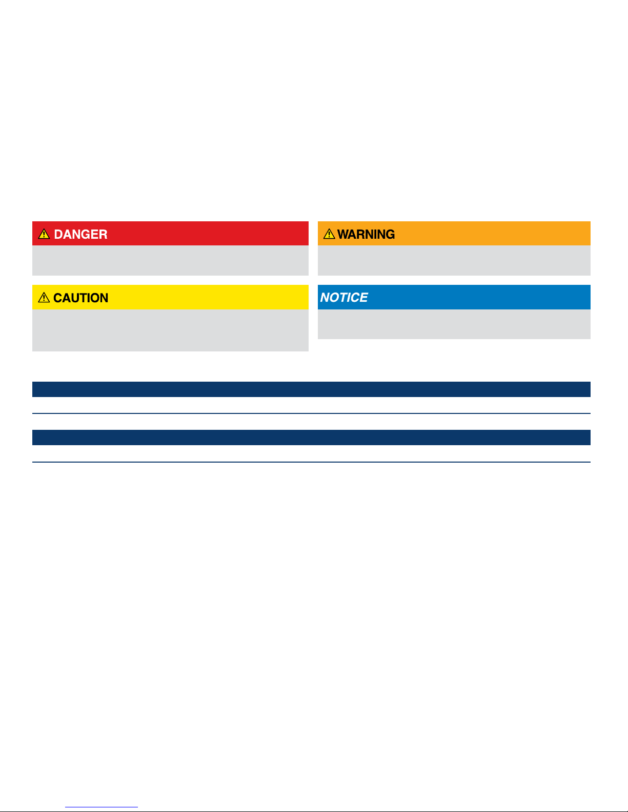
Use of Hazard Information
If multiple hazards exist, the signal word corresponding to the greatest hazard shall be used.
De nitions
DANGER indicates a hazardous situation which, if not
SHALL:
SHOULD:
avoided, will result in death or serious injury.
WARNING indicates a hazardous situation which, if not
avoided, could result in death or serious injury.
CAUTION, used with the safety alert symbol, indicates a
hazardous situation which, if not avoided, could result in
minor or moderate injury.
 NOTE
Information that requires special emphasis.
 TIP
Alternate techniques or clarifying information.
This word is understood to be mandatory.
This word is understood to be advisory.
NOTICE is used to address practices not related to personal
injury.
4 Sentry Equipment Corp
Page 5

General Safety Precautions
Product Selection, Installation, and Use
Improper selection, installation, or use can cause personal injury or property damage. It is solely the responsibility of users,
through their own analysis and testing, to select products suitable for their speci c application requirements, ensure they are
Potential Equipment Hazards
properly maintained, and limit their use to their intended purpose.
Follow proper local, state, and federal regulations for proper installation and operational requirements.
Always use caution and common sense when working with any chemical. Read the product label and Material Safety Data
Sheets (MSDS) carefully and follow the instructions exactly.
Hot surfaces! This equipment may have very hot surfaces. If an operator contacts a hot surface, injury may occur. Use
protective clothing to prevent injury. If other equipment comes in contact with a hot surface, damage to the equipment may
occur. Ensure the area around this equipment is kept clear to prevent damage from occurring.
High pressures! This equipment may contain uids at very high pressures. Prior to installing, removing or maintaining this
equipment, ensure that the equipment is isolated from all connecting piping, the equipment is depressurized, the contents
have been drained, and the equipment is cool.
Moving parts! This equipment may contain moving parts. All drive guards and doors must be secured in place when this
machine is being operated.
Equipment rated TX. Equipment maximum surface temperature depends
on operating conditions. Ensure maximum surface temperature shall stay
below ignition temperature of dust or gas atmosphere where it is installed
based on process conditions. Failure to comply could result in an explosion,
causing serious injury or death to personnel and damage to equipment.
If the sampler is mounted directly to a non-electrically conductive surface,
sampler shall be bonded to a grounding electrode. Failure to comply
could result in sparking, which could lead to an explosion, causing harm to
personnel and equipment.
If the sample container is removed from the sampler, do not insert any
body part or other item into the sample discharge port. Crushing will
occur.
Sentry P2B-ATEX Controller 5
To ensure proper sampler operation, be sure
the sampler is installed in a pipe large enough
for the sampler plunger to extend without
impacting the pipe. Failure to comply will
result in equipment damage and poor sample
quality.
Page 6

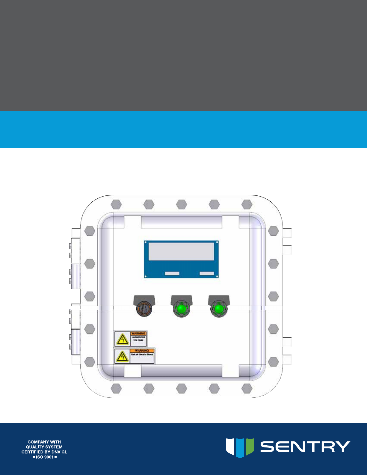
General Description
The Sentry® P2B-ATEX controller is a manually-operated explosion-proof sampler controller used to operate the Sentry
RX, Sentry PR, or Sentry ISOLOK® samplers. The sampler controller is connected to a pneumatic solenoid. The sampler
controller can be used to control the size and frequency of the sample.
Specications
The Sentry P2B-ATEX sampler controller is suitable for use in the following environments:
ZP-XCEX 121208 N4/IP66 EX D (ATEX/IECEX IIB+H2) T6
Installation
Installation should be performed by qualied personnel in accordance with local codes and procedures.
If the sampler controller is to be mounted near the sampler, then the sampler controller must meet the National
Electrical Code for the area. (Sentry Equipment Corp supplies electrical components to meet the standards specied
by the customer. For example, class, division and group as outlined in the National Electrical Code.)
Mount the sampler controller in a location that is easily accessible.
Mount the sampler controller in a vibration-free location and have a qualied electrician wire the sampler controller
to the collection system, motor, limit switch, solenoid (pneumatic), electrical supply, etc.
The sampler controller should be hard wired to instrument-quality power using appropriate certied conduit,
ttings, and wiring or cable.
For xed wiring methods, the ground conductor shall have green with a yellow stripe as the insulation.
Surge suppression and ltering is recommended but not required.
A suitable external over-current protection device—e.g., a fuse or circuit breaker (15 A)—and a disconnect device
are recommended.
– The over-current protection and disconnect devices shall be installed on both the hot (L) and neutral (N) leads.
– The disconnect device shall be located near the equipment and marked with appropriate ON(1) OFF(O) markings
as specied by local codes.
 NOTE
When penetrating the sampler controller enclosure, use tubes & ttings that maintain the environmental rating of the
enclosure.
6 Sentry Equipment Corp
Page 7

Operation
Control Logic
The manual sampler controller included with the sampler is designed to operate the sampler. The control logic
includes:
1. Cycle time: Determines the duration between samples.
2. Sample time: Determines the duration the sample probe is extended into the process. Setting this timer allows the
anulus to ll properly.
3. Manual Sample (HAND): Allows the operator to immediately collect a sample.
4. Automatic Sample (AUTO): Allows the operator to initiate continuous sampling.
5. Auto light: Indicates sampler is currently sampling or is ready for a remote start signal.
6. Batch Complete light: Indicates batch counter has reached the set number.
Sequence of Operation
The sampler controller can operate in manual (HAND) or automatic (AUTO) mode.
When the selector switch is held in the HAND position:
The sampler solenoid is energized.
The sampler solenoid stays energized until the switch is released and it returns to the OFF position.
When the sampler controller is placed in AUTO mode a sample is taken immediately:
The sample timer (TDR 113) starts, the Extend solenoid is energized, the air cylinder extends the sample tube, and a
sample is taken.
When the sample timer expires, the Extend solenoid is de-energized and the air cylinder retracts the sample tube
and the Retract timer (TDR 115) is activated.
When the Retract timer expires, the Extend timer resets and the sample cycle starts again. Sampling continues until
the sampler controller is turned OFF or the batch count is met.
Starting and Stopping the Sampler Controller
Before operating the sampler controller, set the timers to the desired values.
Timers
Set the Extend timer (TDR 113) and Retract timer (TDR 115) by turning the dials to the appropriate time intervals.
When the timers are set, make sure the selector switch is in the OFF position before applying power to the sampler
controller.
TDR 113 is typically set to 5 seconds.
TDR 115 is set at the time required between samples.
TDR 104 should be set to 0.
Sentry P2B-ATEX Controller 7
Page 8

Counter
Set the counter by adjusting the DIP switches.
 NOTE
For CE applications, power must be removed before changing DIP switches.
CTR106
Starting the Sampler Controller
To start the sampler controller and begin sampling, select HAND or AUTO position using the selector switch.
HAND position: Hold the selector switch in the HAND position. The sampler extends and remains extended until
the selector switch is released. When the switch is released, the sampler retracts and the sample is deposited.
AUTO position: Place the switch in AUTO position to initiate continual sampling. A light indicates that the sampler
is in Auto mode. An optional relay is provided to allow remote starts. A jumper must be removed and a circuit must
be completed. See the electrical wiring diagram for details.
Stopping the Sampler Controller
To stop sampling and return the sample probe to the retracted position, place the selector switch in the OFF
position.
 NOTE:
An emergency stop, if required, shall be provided by others.
Reset
To reset the batch counter (CTR-106), place the HOA in the OFF position. Or, it can be done remotely by removing
power from CR-142.
8 Sentry Equipment Corp
Page 9

Maintenance
Normal control maintenance should require draining the water from the lter bowl and replacing the dirty or clogged
lter element. A lockable shut-o valve, available from other suppliers, is required to perform L.O.T.O. procedures.
Always disconnect air before inspection or maintenance of the control or sampler.
With the relieving type of lter or regulator, outlet pressure can be reduced even though the system is dead-ended.
Turn the adjusting knob counter-clockwise to open the relief passage and allow air to escape.
Clean the lter/regulator bowl with warm water only. The polycarbonate plastic bowls used on these lters/regulators can
become damaged and possibly burst if exposed to such substances as certain solvents, strong alkalies, compressor oils
containing ester-based additives, or synthetic oils. Fumes of these substances in contact with the polycarbonate bowl,
externally or internally, also can result in damage.
Filter
Drain lter as frequently as necessary to keep the liquid level in the bowl below the element mounting stud. If the
liquid level rises above the stud, liquid will be carried into air lines. Replace the lter element when plugged or dirty.
1. Shut o inlet pressure. Turn adjusting knob counter-clockwise until it stops, reducing pressure to zero.
2. Remove the bowl and unscrew the mounting stud to replace the lter element.
3. Clean the plastic bowl using warm water only. If the plastic bowl shows signs of cracking, cloudiness or other signs
of deterioration, replace with a metal bowl. Consult Sentry Equipment Corp for replacement parts.
4. Lubricate the o-ring seal before reassembly. Tighten the element stud and/or bowl to 5-10 in lb.
Regulator
Upon detection of air leaks, pressure uctuation or creep, the regulator can be disassembled for cleaning.
1. Shut o the inlet pressure. Turn the adjusting knob counter-clockwise until it stops, reducing pressure to zero.
Remove the entire air control assembly by unscrewing two (2) tube ttings and removing the fasteners holding the
four-way valve to the mounting bracket.
2. Unscrew the plastic bonnet from the regulator and carefully remove parts. Observe arrangement of components
for future reassembly.
3. Clean the parts with warm water and soap. Dry the parts and blow out the internal passage in the body using clean,
dry, compressed air.
4. Inspect the parts carefully and reassemble.
5. Tighten the plastic bonnet to 50–60 in-lb.
6. Replace the air control assembly and tighten the panel nut securely.
Sentry P2B-ATEX Controller 9
Page 10

Standard Warranty
Sentry Equipment Corp (“Seller”) warrants products manufactured by it and supplied hereunder (“Products”) to be free
from defects in workmanship and, to the extent materials are selected by Seller, to be free from defects in materials, in
each case for a period as de ned in the table below:
Brand Product Line Warranty Period
To view the full warranty, go to
Customer Support
With proven sampling expertise since 1924, Sentry products and services provide business operations the critical
insights to optimize process control and product quality. We deliver true representative sampling and analysis
techniques to customers around the globe, empowering them to accurately monitor and measure processes for
improved production effi ciency, output, and safety. Standing behind our commitments, we are determined to tackle
any application, anywhere.
We know that running an effi cient operation isn’t easy. It requires thorough, careful analysis of controlled, realtime data achieved through reliable, accurate, and repeatable process monitoring, and measuring. By e ectively
conditioning, sampling, and measuring gas, liquid, slurry, powder, solids, steam, or water within their production
environments, our customers obtain the critical insights they need to control and optimize their processes.
Yet, controlling your processes also means reliable customer support throughout the life cycle of your equipment.
Sentry ProShield Services – select from four ProShield Guardian service plans providing di erent levels of support to
To learn more, go to
Sentry® Steam & Water Sampling Products and Systems
Solid & Powder Sampling Products and Systems
Gas Sampling Products and Systems
Liquid & Slurry Sampling Products and Systems
Corrosion Monitoring Products
Waters Equipment Steam & Water Sampling Products and Systems Twelve months from date of shipment
www.sentry-equip.com/warranty.
Eighteen months from date of shipment
or twelve months from startup (whichever
occurs rst)
Customer Service—General information, warranty claims, order management.
Installation Service—For systems that require specialized expertise upon installation.
Technical Support—Troubleshooting, training, and technical manuals.
Field Service & Retro ts—When a problem needs immediate attention.
Replacements Parts & Consumables—Order your replacement parts and consumables.
protect your large system investments with regularly scheduled maintenance.
www.sentry-equip.com/support.
10 Sentry Equipment Corp
Page 11

This page is intentionally left blank.
Sentry P2B-ATEX Controller 11
Page 12

Serving customers
in more than 50 countries
across six continents worldwide.
sentry-equip.com
966 Blue Ribbon Circle North, Oconomowoc, WI 53066 U.S.A. | +1-262-567-7256 | support@sentry-equip.com
 Loading...